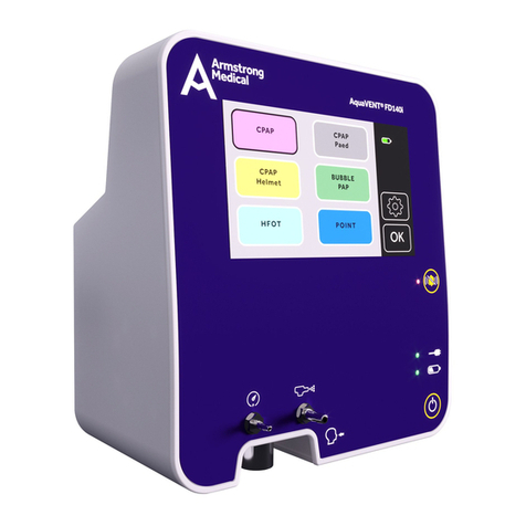
Armstrong Medical AquaVENT FD140i User manual

Technical Manual
AquaVENT®FD140i
Version: 1.0

2AquaVENT®FD140i Technical Manual (v1.0)

AquaVENT®FD140i Technical Manual (v1.0) 3
Table of Contents
1.0
1.1
1.1.1
1.1.2
1.1.3
1.2
1.3
7
8
8
8
9
9
10
2.0
2.1
2.2
2.2.1
2.2.2
2.2.3
2.3
2.4
2.4.1
2.4.2
2.4.3
11
12
12
12
13
17
19
22
23
23
24
3.0
3.1
3.1.1
3.2
3.2.1
3.3
3.3.1
3.3.2
3.3.3
3.3.4
Introduction
Guidelines for this technical manual
- Instructions for use
- Software and Hardware version
- Standard service procedures
Symbols
Abbreviations
AquaVENT®FD140i Overview
General description
AquaVENT®FD140i features
- Safety features
- Device layout
- Device interface and icons
Pneumatic Components
Electrical Components
- Main Board
- Pneumatic Assembly
- AquaVENT®FD140i Housing
Calibration and Testing
Calibration and Testing
- Self-Check
Service Mode
- Service mode pages
Calibrations
- Osensor calibration
- O
- Patient pressure sensor calibration
Table of Contents
27
28
28
31
32
35
36
37
38
38

4AquaVENT®FD140i Technical Manual (v1.0)
Table of Contents
Maintenance and Service
General instructions
Maintenance schedule
Service kits
Repair Procedures
General instructions
- Tools
Ordering spare parts
Opening the device
- Opening the housing
- Removing the pneumatic assembly
- Device assemblies
Software update
Replacing main unit components
- Replacing battery
- Replacing LCD screen
- Replacing display PCB
- Replacing coin cell
- Replacing alarm loudspeaker
- Replacing fan assembly
- Replacing power entry connector
- Replacing power supply unit
- Replacing USB assembly
Replacing pneumatic assembly components
- Replacing tube, nebuliser & patient pressure measurement connector
- Replacing pneumatic assembly circuit board
- Replacing patient pressure sensor
51
52
52
53
5.0
5.1
5.2
5.3
59
60
60
60
61
61
62
63
65
67
67
68
69
70
71
72
73
74
75
76
76
76
77
6.0
6.1
6.1.1
6.2
6.3
6.3.1
6.3.2
6.3.3
6.4
6.5
6.5.1
6.5.2
6.5.3
6.5.4
6.5.5
6.5.6
6.5.7
6.5.8
6.5.9
6.6
6.6.1
6.6.2
6.6.3
4.0
4.1
4.2
4.2.1
4.2.2
4.2.3
4.3
4.3.1
4.3.2
Device Troubleshooting
Troubleshooting instructions
Alarms
- Patient alarms
- Device alarms
- FiOalarms
Messages
- Messages during system test
- Messages during Osensor calibration
43
44
45
45
45
46
47
47
49
3.3.5
3.3.6
3.4
3.5
- Nebuliser set-up
- Touchscreen calibration
Mechanical free-breathing valve test
Post-service checkout
Gas Flow Driver Safety Check
sheet
39
39
40
40
41

AquaVENT®FD140i Technical Manual (v1.0) 5
Table of Contents
78
79
80
81
82
83
84
85
86
87
88
89
6.6.4
6.6.5
6.6.6
6.6.7
6.6.8
6.6.9
6.6.10
6.6.11
6.6.12
6.6.13
6.6.14
6.6.15
- Replacing proportional valves
- Replacing pressure switches
- Replacing pressure regulators
- Replacing nebuliser valve
- Replacing gas inlet connectors
- Replacing o-rings at gas inlet connectors
- Replacing paramagnetic oxygen sensor
- Replacing over pressure valve
- Replacing mechanical free-breathing valve
- Replacing fuel cell
Illustrated Parts
Service tools
- Tools
Main unit spare parts
Pneumatic assembly spare parts
93
94
94
94
96
99
7.0
7.1
7.1.1
7.1.2
7.2
7.3
Appendices
Connectors main board
Connectors pneumatic assembly board
Complete spare parts list
Revision updates
105
106
107
108
110
8.0
8.1
8.2
8.3
8.4

6AquaVENT®FD140i Technical Manual (v1.0)
This page is intentionally blank

AquaVENT®FD140i Technical Manual (v1.0) 7
Introduction
1.0 Introduction

8AquaVENT®FD140i Technical Manual (v1.0)
Introduction
1.1 Guidelines for this technical manual
1.1.1 Instructions for use
1.1.2 Software and Hardware version
This manual covers service information for the
AquaVENT®FD140i Gas Flow Driver
Some information in this technical manual can possibly point the reader to electronic
troubleshooting and component repair / replacement level of service. This information,
when supplied, is only supplied to add clarity to service or troubleshooting statements.
Authorised service technicians are permitted to service electronic equipment to a board
replacement level only.
• Read completely through each step in every procedure before starting the
procedure; any exceptions can result in a failure to complete the attempted
procedure properly and safely.
•
• Chapters in this manual begin on odd-numbered or right-hand pages. If there is no
text on the preceding page, it is labelled ‘intentionally blank page’ for your use if you
wish.
You have to be familiar with the instructions for use of the AquaVENT®FD140i. Study
the instructions for use if you need further information about the operation of the
system.
The current software version will be displayed during Self-Check. For details
refer to image in 3.1.1 Self-Check. Details concerning a software update of the
AquaVENT®FD140i can be found in 6.4 Software update.
The current hardware version is not actively displayed on the device.
Optionally, the AquaVENT®FD140i
sensor and / or an oxygen (fuel cell) analyser.
The oxygen sensor continuously measures the FiOand shows this on the
screen. The oxygen sensor requires no maintenance during it's lifetime, but it
must be calibrated regularly (at least once each month).
Warning
Software
Hardware
Options
This manual includes calibration and test procedures for software version 1.01
and hardware version 1.01 and 1.02.
All service, repair and maintenance procedures as well as the setting of

AquaVENT®FD140i Technical Manual (v1.0) 9
Introduction
Warning
Normal operational tests, calibrations and troubleshooting can be performed on
the AquaVENT®FD140i without opening the system’s housing. Only repair and
replacement procedures require opening the system’s housing.
Do not perform tests or maintenance on the AquaVENT®FD140i while it is being used
to treat a patient. Possible injury may result.
1.1.3 Standard service procedures
1.2 Symbols
Warning to indicate a condition that can cause injury to the user or the patient.
Carefully read and follow all warning statements.
Caution to indicate a condition that can cause damage to the equipment.
Carefully read and follow all caution statements.
The AquaVENT®FD140i
provided that it is operated in accordance with its instructions for use. ‘1639’ is the
The AquaVENT®FD140i
guidelines. Please contact the manufacturer in order to receive information
regarding correct disposal.
Adhere to instructions for use.
USB Type B connection - located at the rear of the device.
Warning
Caution
After the AquaVENT®FD140i has been serviced, the ‘Post-service Checkout’
has to be performed to verify that the system is properly functioning before
the system can be returned to clinical use. For details refer to ‘3.5 Post-service
checkout’.
The following symbols are used within the technical manual and device to communicate
and/or highlight information. Icons relevent to the usage of the device can be found in
2.2.3 Device interface and icons.
‘Warning’ and ‘Caution’ tell you about dangerous conditions that can occur if you do not
follow all instructions in this manual.
1639

10 AquaVENT®FD140i Technical Manual (v1.0)
Introduction
1.3 Abbreviations
The following is a list of abbreviations used in this manual and device.
Medical air
Medical oxygen
Continuous Positive Airway Pressure
Positive Airway Pressure
Positive End Expiratory Pressure
Fraction of inspired oxygen
Hardware version
Software version
Serial number
Pulse width modulation
Real-Time Clock
Flash memory
Low drop-out
Integrated circuit
AIR
O2
CPAP
PAP
PEEP
FiO2
HW
SW
Ser.- No.
TFT
PWM
RTC
MEM Rd/Wr
LDO
IC

AquaVENT®FD140i Technical Manual (v1.0) 11
AquaVENT®FD140i Overview
2.0 AquaVENT®FD140i Overview

12 AquaVENT®FD140i Technical Manual (v1.0)
AquaVENT®FD140i Overview
2.1 General description
The AquaVENT®FD140i
air and oxygen to the patient via an attached breathing circuit. The device has six preset
respiratory therapies:
• CPAP
• CPAP Paed
• CPAP Helmet
• BUBBLE-PAP
• HFOT
• POINT®
For a description of each therapy please refer to the User Manual.
Each therapy mode has customised settings according to the therapy characteristics.
medical air for driving a jet nebuliser containing liquid drug suspension.
AquaVENT®FD140i incorporates a user-friendly touch screen facilitating intuitive
operation. It is equipped with a sophisticated alarm system and advanced oxygen
sensing technology that collaborate to safeguard patient care. Additionally, the device
has an internal Li-ion battery for uninterrupted operation in the event of temporary
disconnection from the mains power supply.
2.2.1 Safety features
• Visual and audible alarm system
• Mechanical under-pressure valve (free-breathing valve)
• Single gas operation capability for AIR and O
2.2 AquaVENT®FD140i features
• On-board diagnostic software to ease servicing
• Service mode
• System test
• Monitoring of the CPAP value
• Adjustable Osupply concentration
• Multi-language on-board software
• Touchscreen panel
• External communication via USB interface
• Optional Osensor for measuring FiO
• Option between paramagnetic sensor or fuel cell operation
• Demonstration mode for non-clinical use

AquaVENT®FD140i Technical Manual (v1.0) 13
AquaVENT®FD140i Overview
2.2.2 Device layout
8
7
6
5
4
2 31
Pressure measurement port
Respiratory gas outlet
Nebuliser port
Touchscreen
Alarm mute button
Mains power connection indicator
Battery status indicator
Power ON/OFF button
1
2
3
4
5
6
7
8

14 AquaVENT®FD140i Technical Manual (v1.0)
AquaVENT®FD140i Overview
2.2.2 Device layout (cont’d)
11
10
9
Refer to instruction manual
Mains power inlet
USB port
9
10
11

AquaVENT®FD140i Technical Manual (v1.0) 15
AquaVENT®FD140i Overview
2.2.2 Device layout (cont’d)
Handle
Fan outlet
Fixation claw
Serial plate
Medical oxygen inlet (NIST)
Medical air inlet (NIST)
12
13
14
15
16
17
17
16
15
12
14
13

16 AquaVENT®FD140i Technical Manual (v1.0)
AquaVENT®FD140i Overview
2.2.2 Device layout (cont’d)
18
19
Over-pressure relief valve (do not obstruct)
Mechanical under-pressure (free-breathing valve) (do not obstruct)
18
19

AquaVENT®FD140i Technical Manual (v1.0) 17
AquaVENT®FD140i Overview
2.2.3 Device interface and icons
Front panel icons and indicator lights:
Power source indicators
AC mains power supply is connected when indicator light is illuminated
Running on internal battery when indicator light is illuminated solid green
Buttons
Alarms
Gas ports
Power ON/OFF device
Warning - alarm activated
Respiratory gas outlet
Alarm silenced
Patient Pressure measurement connection
Alarm audio is sounding when indicator light is solid red
Nebuliser port
Touchscreen icons:
Screen locked

18 AquaVENT®FD140i Technical Manual (v1.0)
AquaVENT®FD140i Overview
Power supply and battery charge indication
General settings
Therapy setting
Device unplugged from mains power
General settings menu
Therapy timer
Screen brightness
Return to previous menu
Adjust alarm settings Start therapy
Decrease value incrementally Nebuliser gas supply on
Language selection
Touch tone volume
Select approximate value Stop therapy
Minimum permissible value Respiratory gas values
Battery charging
Alarm volume
Increase value incrementally
Maximum permissible value In therapy icon
Charging

AquaVENT®FD140i Technical Manual (v1.0) 19
AquaVENT®FD140i Overview
2.3 Pneumatic components
This section will describe the components contained within the pneumatic
assembly of the AquaVENT®FD140i.
All components are located on the pneumatic assembly, excluding the following
components, which are components included in a breathing circuit:
• PEEP valve
• Patient connector 0-140L/min
• Nebuliser
The following diagram illustrates the components contained within the pneumatic
assembly and how they are connected.
Label Description
GI1 Gas Input - AIR
GI2 Gas Input - O
F1
F2 O
PR1 Pressure regulator - AIR
PR2 Pressure regulator - O
PS1 AIR supply monitor
PS2 Osupply monitor

20 AquaVENT®FD140i Technical Manual (v1.0)
AquaVENT®FD140i Overview
The gas supply connectors (GI1 for AIR and GI2 for O) are screw-in
ensure no unwanted particles enter the system.
AIR (PR1) and O(PR2) pressure regulators are employed to regulate the
input pressure to the device. These regulate the input pressure to a level of
approximately 300kPa (44 PSI).
Pressure sensors for AIR (PS1) and O(PS2) are used to monitor the gas
pressure input to be above a minimum operating pressure of 180kPa (26 PSI).
pressure sensor (S3).
Gas supply
Pressure
Regulators
Pressure
sensor
AIR ow
controller
PV1 Proportional valve - AIR
PV2 Proportional valve - O
S1 Flow sensor - AIR
S2 Flow sensor - O
M1 Flow mesh - AIR
M2 Flow mesh - O
VC1 Volume chamber
SV1 Nebuliser valve
RS1 Stenosis restrictor
OS1/OS2 OConcentration Sensor
RV1 Free-breathing valve
RV2 Over-pressure valve
S3 Patient Pressure sensor
A01 Nebuliser connector 4-12L/min
A02 Nebuliser
A03 Tube connector
A04 Leakage
A05 PEEP valve
A06 Patient connector 0-140L/min
Other manuals for AquaVENT FD140i
2
Table of contents
Other Armstrong Medical Medical Equipment manuals
