Stryker Endoscopy 1088 Operating instructions


Table of Contents
1
Table of Contents . . . . . . . . . . . . . . . . . . . . . . . . . . . . . 1
Warnings and Cautions. . . . . . . . . . . . . . . . . . . . . . . . 3
Symbol Definitions . . . . . . . . . . . . . . . . . . . . . . . . . . . . . . . . 5
Product Description and Intended Use . . . . . . . . . 7
The Camera Console . . . . . . . . . . . . . . . . . . . . . . . . . . . . . . . 7
The Camera Head . . . . . . . . . . . . . . . . . . . . . . . . . . . . . . . . 10
The Coupler . . . . . . . . . . . . . . . . . . . . . . . . . . . . . . . . . . . . 11
Setting Up the 1088 Camera . . . . . . . . . . . . . . . . . . 12
Setting Up the Console . . . . . . . . . . . . . . . . . . . . . . . . . . . . 12
Setting Up the Camera Head. . . . . . . . . . . . . . . . . . . . . . . . . 17
Setting Up the Coupler. . . . . . . . . . . . . . . . . . . . . . . . . . . . . 18
Operating the 1088 Camera . . . . . . . . . . . . . . . . . . . 20
Using the Console Controls . . . . . . . . . . . . . . . . . . . . . . . . . 20
Powering On the Camera . . . . . . . . . . . . . . . . . . . . . . . . . 20
Using the White Balance Switch . . . . . . . . . . . . . . . . . . . . . 20
Using the Gain Button . . . . . . . . . . . . . . . . . . . . . . . . . . . 21
Using the Enhance (Up and Down) Buttons . . . . . . . . . . . . . 21
Selecting a Surgical Specialty . . . . . . . . . . . . . . . . . . . . . . 21
Using the Light/Zoom Switch . . . . . . . . . . . . . . . . . . . . . . . 21
Using the Shutter Switch. . . . . . . . . . . . . . . . . . . . . . . . . . 22
Using the NTSC/PAL Switch . . . . . . . . . . . . . . . . . . . . . . . 22
Controlling Remote Video Accessories . . . . . . . . . . . . . . . . 22
Using the Camera Head Buttons . . . . . . . . . . . . . . . . . . . . . . 23
Using the P Button. . . . . . . . . . . . . . . . . . . . . . . . . . . . . . 23
Using the W Button . . . . . . . . . . . . . . . . . . . . . . . . . . . . . 24
Using the Up and Down Buttons . . . . . . . . . . . . . . . . . . . . . 24
Cleaning and Maintaining the 1088 Camera . . . 25
Cleaning the Camera Console. . . . . . . . . . . . . . . . . . . . . . . . 25
Table of Contents

2
Cleaning the Camera Head . . . . . . . . . . . . . . . . . . . . . . . . . . 25
Disinfecting the Camera Head. . . . . . . . . . . . . . . . . . . . . . . . 26
Sterilizing the Camera Head . . . . . . . . . . . . . . . . . . . . . . . . . 27
100% Ethylene Oxide Gas . . . . . . . . . . . . . . . . . . . . . . . . 27
Steris System . . . . . . . . . . . . . . . . . . . . . . . . . . . . . . . . . 28
Sterrad System . . . . . . . . . . . . . . . . . . . . . . . . . . . . . . . . 28
Using Sterile Drapes . . . . . . . . . . . . . . . . . . . . . . . . . . . . 29
Maintaining the 1088 Camera . . . . . . . . . . . . . . . . . . . . . . . . 29
Replacing the Fuses . . . . . . . . . . . . . . . . . . . . . . . . . . . . 29
Periodic Maintenance Schedule . . . . . . . . . . . . . . . . . . . . . 29
Disposing of the 1088. . . . . . . . . . . . . . . . . . . . . . . . . . . . 29
Troubleshooting. . . . . . . . . . . . . . . . . . . . . . . . . . . . . . 30
Electromagnetic Compatibility Tables. . . . . . . . . 33
Technical Specifications. . . . . . . . . . . . . . . . . . . . . . 37
Warranty . . . . . . . . . . . . . . . . . . . . . . . . . . . . . . . . . . . . . 39
Service and Claims . . . . . . . . . . . . . . . . . . . . . . . . . . . 40
International Service . . . . . . . . . . . . . . . . . . . . . . . . . 41

Warnings and Cautions
3
Please read this manual and follow its instructions carefully. The words
warning, caution, and note carry special meanings and should be
carefully reviewed:
Warning The personal safety of the patient or physician may be
involved. Disregarding this information could result in
injury to the patient or physician.
Caution Special service procedures or precautions must be
followed to avoid damaging the instrument.
Note Special information to make maintenance easier or
important information more clear.
An exclamation mark within a triangle is intended to alert
the user to the presence of important operating and
maintenance instructions in the literature accompanying
the product.
A lightning bolt within a triangle is intended to warn of the
presence of hazardous voltage. Refer all service to
authorized personnel.
Warning To avoid potential serious injury to the user and
patient, and/or damage to this device, the user must:
1. Read this operating manual thoroughly and be familiar with
its contents prior to using this equipment.
2. Carefully unpack the unit and check if any damage
occurred during shipment. If damage is detected, please
refer to the Service and Claims section in this manual.
3. Be a qualified physician, having complete knowledge of the
use of this equipment.
4. Test this equipment prior to a surgical procedure. This unit
was fully tested at the factory before shipment.
5. Avoid removing covers on the control unit, as doing so may
break the camera-head seals or cause electric shock.
6. Attempt no internal repairs or adjustments not specifically
detailed in this operating manual.
7. Pay close attention to the care and cleaning instructions in
this manual. A deviation may cause damage.
Warnings and Cautions

4
8. Never sterilize the camera console.
9. Disconnect the control unit from the electrical outlet when
inspecting the fuses.
10. Read the entire instruction manual before assembling or
connecting the unit.
11. Before each use, check the outer surface of the endoscope
to ensure that there are no rough surfaces, sharp edges, or
protrusions.
The warranty is void if any of these warnings is disregarded.
Stryker Endoscopy accepts full responsibility for the effects on safety,
reliability, and performance of the equipment only if:
• Readjustments, modifications, and/or repairs are carried out
exclusively by Stryker Endoscopy.
• The electrical installation of the relevant operating room complies
with the applicable IEC, CEC, and NEC requirements.
Stryker Endoscopy reserves the right to make improvements to the
product(s) described herein. Product(s), therefore, may not agree in detail
to the published design or specifications. All specifications are subject to
change without notice. Please contact the local Stryker Endoscopy
Distributor listed in the Other Service section, or phone your local Stryker
Endoscopy sales representative or agent for information on changes and
new products.
Warning Federal law (United States of America) restricts this
device to use by, or on order of, a physician.

Warnings and Cautions
5
Symbol Definitions
In addition to the cautionary symbols already listed, other symbols found
on the 1088 Camera and in this manual have specific meanings that
clarify the proper use and storage of the 1088 Camera. The following list
defines the symbols associated with this product.
Operating humidity ratings
Operating pressure ratings
Operating temperature ratings
Denotes compliance to CAN/CSA C22.2 No 601.1-M90
and UL2601-1.
Type BF applied part
Equipotentiality
Protective earth ground

6

Product Description and Intended Use
7
The Stryker Endoscopy Model 1088 Medical Video Camera is a high-
definition camera used to capture still and video images of endoscopic
surgical applications. The 1088 Medical Video Camera consists of three
main components:
• the camera console
• the camera head
• the focusing coupler
The 1088 also comes with various cables, which like the other
components, can be purchased together or separately.
The Camera Console
The camera console is the control center for the 1088 Medical Video
Camera and processes the video and photographic images captured
during the surgical procedure. The front console panel features controls
for adjusting the enhance, gain, and white balance, and for selecting
surgical specialty settings that optimize camera performance for specific
surgical procedures.
The rear console panel provides ports for connecting the 1088 Camera to
viewing and recording equipment, such as video monitors, the SDC HD,
or photo printers.
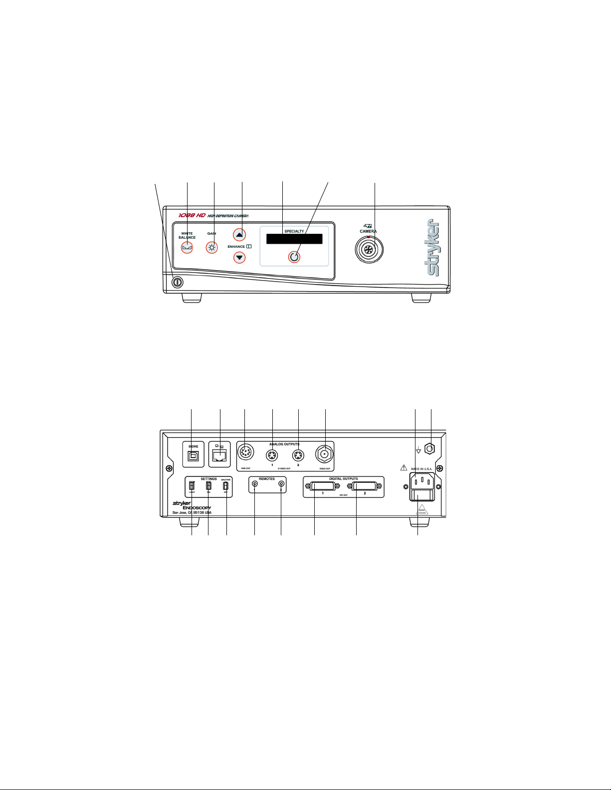
The features of the front and rear console panels are listed in Figure 1.
Product Description and Intended Use
8
Figure 1a: The 1088 Camera console, front panel
Figure 1b: The 1088 Camera Console, rear panel
12 5 6 734
8910 11 12 13 14 15
16 17 18 19 20 21 22 23

Product Description and Intended Use
9
1. Power Switch: Powers the camera on and off
2. White Balance Button: Starts the white balance operation
3. Gain Button: Selects four levels of light sensitivity settings
4. Enhance Buttons: Increase or decrease image sharpness
5. Specialty Screen: Displays which surgical preset has been
selected
6. Specialty Button: Selects different surgical presets
7. Camera Connector: Connects to the 1088 Camera Head
8. Sidne™ Port: Connects to the Sidne™ Console to enable voice
operation
9. Ethernet Port: Provides an ethernet connection for remote
diagnoses and future software upgrades
10. RGB Out
11. S-Video 1Out
12. S-Video 2 Out
13. Composite Out
14. AC Power Inlet
15. Equipotential Ground Plug
16. Light/Zoom Switch: Selects either the LIGHT or ZOOM function
for the arrow buttons on the camera head
17. NTSC / PAL Switch: Selects NTSC or PAL video signals for
analog outputs
18. Shutter Switch: Enables / disables the auto shutter
19. Remote Out 1: Connects to a video accessory remote switch
20. Remote Out 2: Connects to a video accessory remote switch
21. DVI Out 1
22. DVI Out 2
23. Fuse Panel: Contains two 0.63A fuses

10
The Camera Head
The camera head connects to the camera console and captures video
and photographic images, which it relays to the camera console. It
features several controls that are accessible through a button control pad
located on the top of the camera head (see the Operating the Camera
Head section of this manual).
Figure 2 below lists the features of the camera head.
Figure 2: The 1088 HD Camera Head
1. Soaking Cap: Protects the cable connector during cleaning and
sterilization
2. Camera Head: Captures photographic and video images,
provides camera controls, and connects to a focusing coupler
3. Camera Cable
4. Cable Connector: Connects the camera head to the camera
console
1
2
3
4
Product Description and Intended Use
11
The Coupler
The coupler threads on to the face of the camera head, enabling a scope
to be attached to the camera. It provides a focusing ring to adjust image
sharpness.
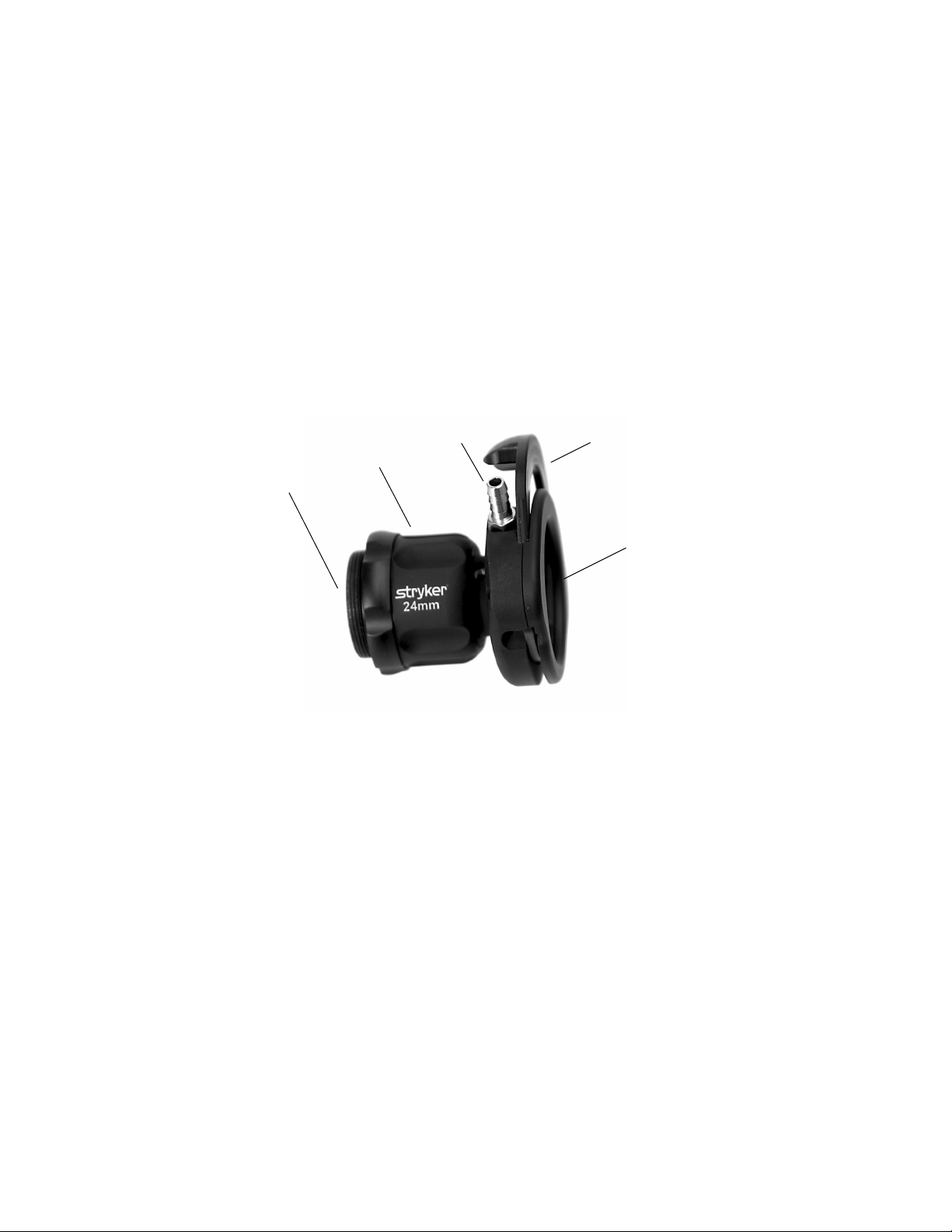
The features of the coupler are listed in Figure 3 below.
Figure 3: The coupler
1. Camera End: Threads onto the camera head
2. Focusing Ring: Adjusts the coupler focus
3. Ventilation Port: Provides ventilation for the coupler lens
4. Endobody Clamp: Secures the scope to the coupler
5. Scope End: Receives the endoscope
1
2
34
5

12
Note Stryker Endoscopy considers instructional training, or in-
service, as an integral part of the 1088 Medical Video
Camera. Your local Stryker Endoscopy sales
representative will perform at least one in-service at your
convenience to help set up your equipment and instruct
you and your staff on its operation and maintenance. To
schedule an in-service, contact your local Stryker
Endoscopy representative after your equipment has
arrived.
Setting Up the 1088 Camera involves three steps:
1. Setting up the console
2. Setting up the camera head
3. Setting up the coupler
Setting Up the Console
Caution Portable and mobile RF communications equipment may
affect the normal function of the 1088 Camera. When
choosing a location for the 1088 Camera, consult the
“Electromagnetic Compatibility” section of this manual to
ensure proper function.
To set up the console, make the following connections:
1. Connect the AC power.
• Connect the AC power cord to the AC inlet on the rear console
panel.
• Connect the other end to a hospital-grade outlet.
Warning Always use the hospital-grade power cord supplied
with this camera.
Setting Up the 1088 Camera
Setting Up the 1088 Camera
13
2. Connect the video output.
• The rear panel provides four analog and two digital-video
outputs, which can be used together or independently:
• Use the cables and outputs described above to connect the
1088 to other operating-room equipment. Diagrams 1-3 on the
following pages describe typical set-ups.
• If desired, connect any remote outputs using the remote cables
supplied with the 1088 Camera. (See Diagram 2.) Devices
connected to the remote outputs of the 1088 Camera can be
operated by using the buttons on the camera head. See the
“Operating the Camera Head” section of this manual for details.
• If desired, connect the Sidne™ interface as well. (See Diagram
2.)
Warning When the 1088 Camera is used with other equipment,
leakage currents may be additive. Ensure that all
systems are installed according to the requirements of
IEC 60601-1-1.
Warning Do not touch the internal pin of the VIDEO-OUT BNC
jack and the patient simultaneously.
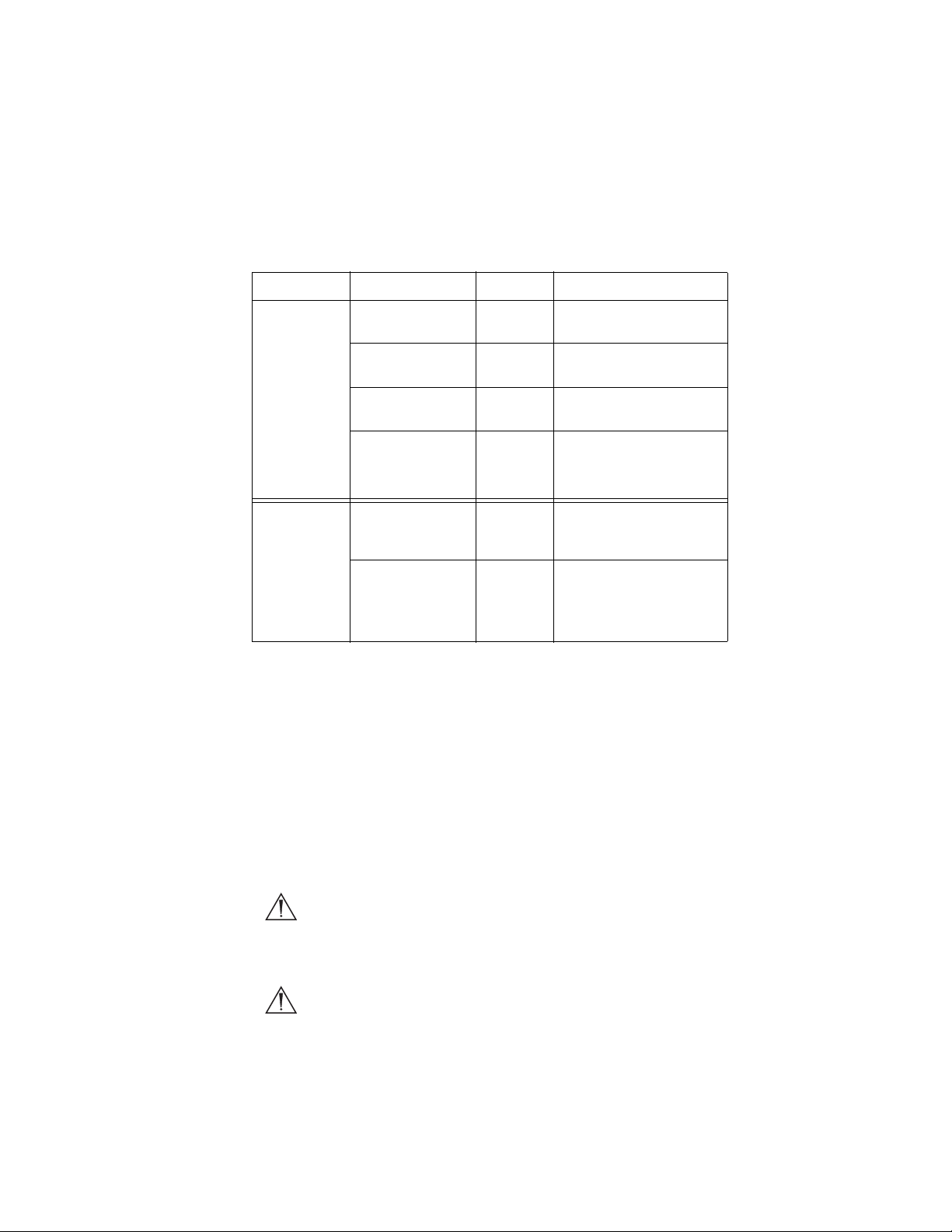
Output Type Output Cable Connector
Analog RGB RGB 8-pin DIN (push-only
connectors)
Composite Composite BNC (push-and-turn
connectors)
*S-VHS 1 S-VHS 4 pin Mini-Din (push-only
connectors)
*S-VHS 2
*On some monitors, S-
VHS inputs may be
labeled Y/C.
S-VHS 4 pin Mini-Din (push-only
connectors)
Digital **DVI-I 1 DVI 29-pin (push-only
connectors, with two
tightening knobs)
**DVI-I 2
**The DVI connectors can
also output analog SXGA
signals through a DVI-I to
VGA adapter.
DVI 29-pin (push-only
connectors, with two
tightening knobs)

14
Wiring Diagram 1: Camera, Light Source and Flat-Panel Monitor
DVI-I / VGA
Adapter
Flat-Panel Monitor
1088 Camera
X7000 Light Source
DVI
BNC
DVI

Setting Up the 1088 Camera
15
Wiring Diagram 2: Camera, Light Source, SDC Pro HD, Sidne™, and
Flat-Panel Monitor
1088 Camera
DVI
Sidne™
StrykerVision 1 Monitor
X7000 Light Source
SDC HD
DVI
DVI
Remote
Remote
BNC
USB

16
Wiring Diagram 3: Camera, Light Source, Flat-Panel Monitor, and
CRT Monitor
Note If you are using any device with unterminated analog video
inputs, you must connect a cable from the VIDEO OUT of
that device to the VIDEO IN on the monitor.
Note An additional monitor may be connected using any open
camera output.
3. Power on the monitor.
4. Power on the camera.
Note A color bar pattern will appear on the monitor when the
camera head is not connected to the camera console.
Follow the instructions in the “Setting Up the Camera
Head” section of this manual to connect the camera head
to the console.
X7000 Light Source
VGA
1088 Camera
CRT Monitor
StrykerVision 1 Monitor
DVI
S-VHS
BNC
DVI-I / VGA
Adapter
DVI

Setting Up the 1088 Camera
17
Setting Up the Camera Head
1. Connect the camera head to the console.
• Unscrew the soaking cap from the cable connector if
necessary.
• Align the red dot on the cable connector with the red dot on the
camera-connector port on the front console panel (see Figure 4).
• Push in the connector until it locks in place.
Figure 4: Connecting the camera head to the console
Note To unplug the camera from the control unit, grasp the
knobbed portion of the connector and pull straight out. This
releases the connector latching mechanism.
Caution Do not severely bend the camera cable or damage may
result.

18
Setting Up the Coupler
1. Attach the coupler to the camera head.
• Twist the camera end of the coupler into the camera head
(clockwise) until it forms a tight seal (see Figure 5).
Figure 5: Attaching a coupler to the camera head
Caution Do not overtighten the coupler, as this may damage
the front window of the camera.
Note For direct-coupled scopes (scopes that require no coupler),
thread the endoscope directly into the camera head until it
forms a tight seal.
Caution Do not overtighten a direct-coupled scope, as this may
damage the front window of the camera.
Table of contents
Other Stryker Endoscopy Medical Equipment manuals


