Tommy User Guide
4. Operation
No part of this User Guide may be reproduced, stored in a retrieval system, or published, in any form or by any means, electronic,
mechanical, photocopying, recording or otherwise, without the prior written permission of Atlas Revalidatie Techniek BV.
© 2007 Atlas Revalidatie Techniek B.V.
10
4.2 Standard settings
(it is advisable to have these settings fixed by a paramedic)
A number of standard settings must be fixed in accordance with the child’s length, weight and
handicap; these will have to be altered after a while, if necessary in consultation with the attending
therapist.
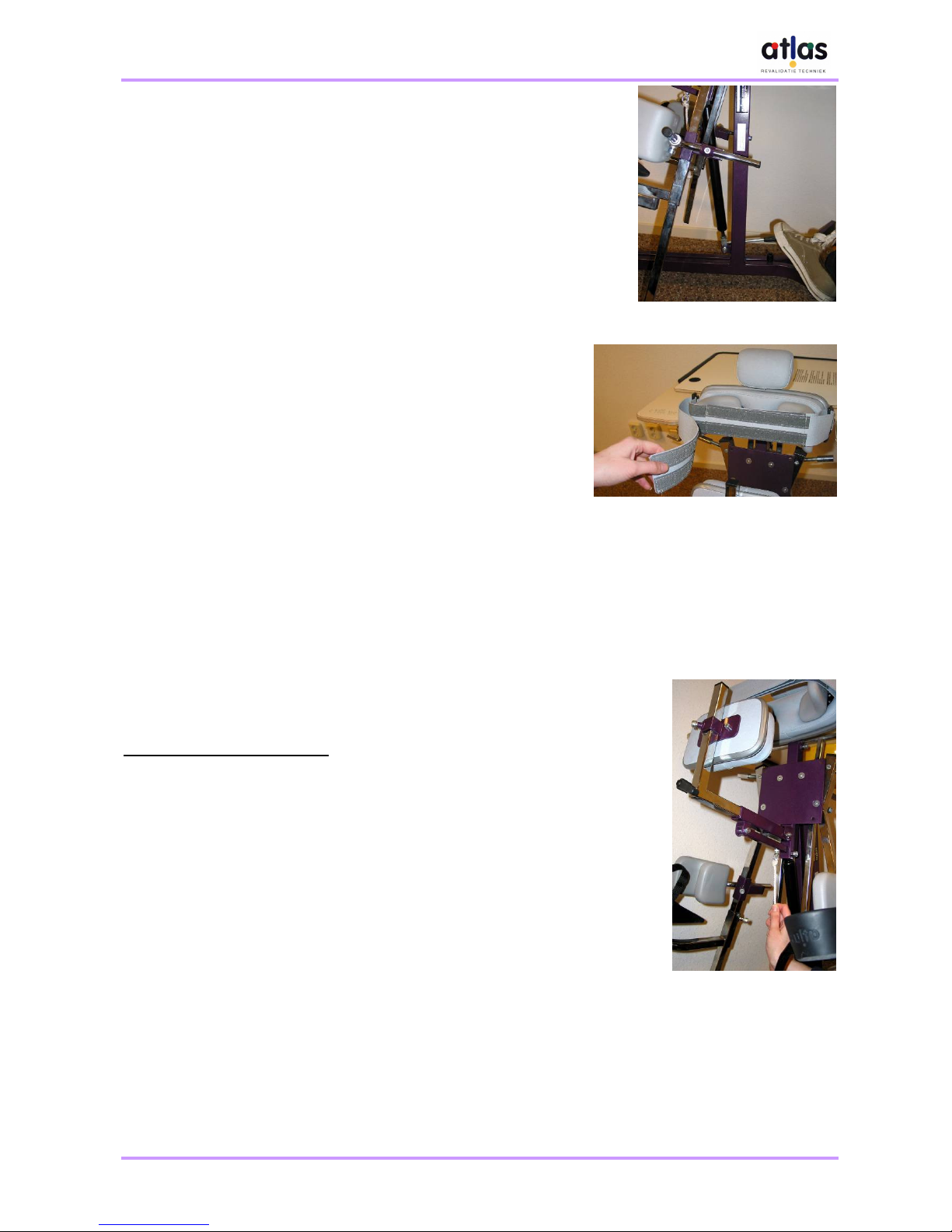
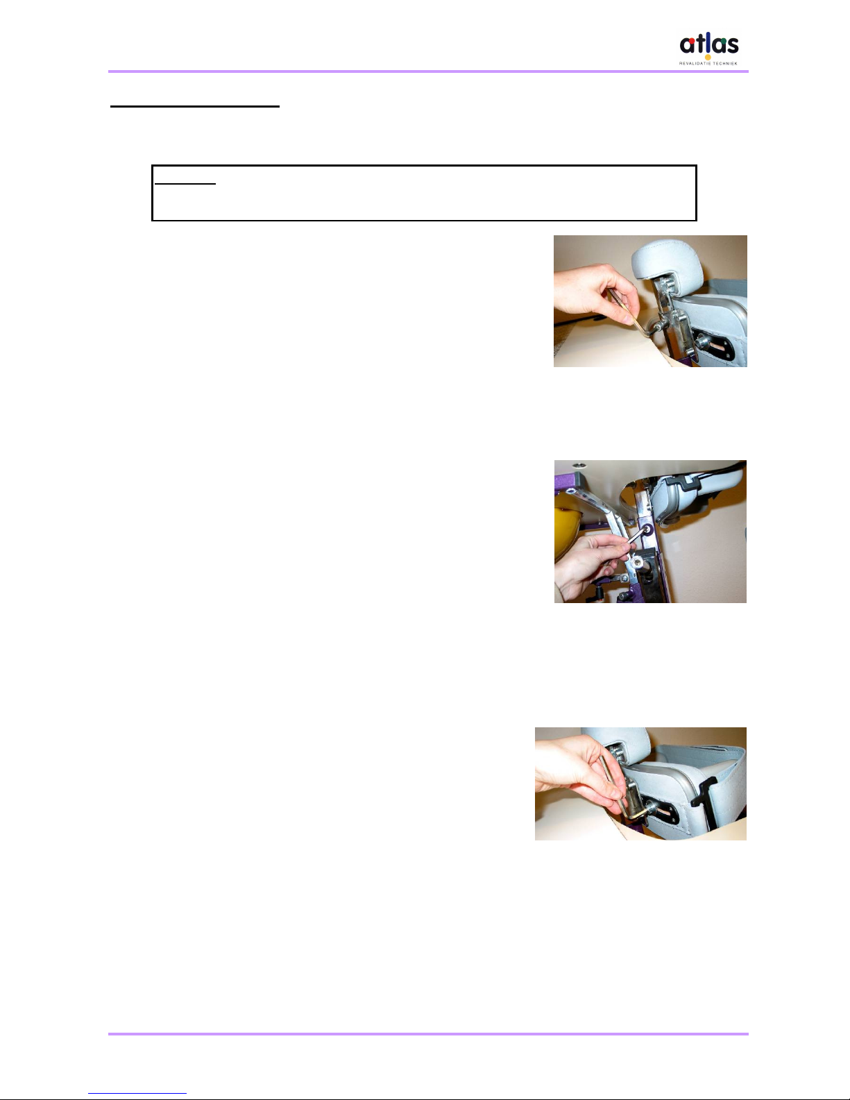
4.2.1 The height of the chin support
•The screw for adjusting the height of the chin support is located
on the back of the chest support (see illustration 10). You will
need hexagonal key (Allen key) number 6 to make this
adjustment.
•Hold the chin support firmly with one hand and loosen the
adjusting screw with the other. Adjust the chin support to the
required height and tighten the screw firmly again. Check that
the chin support is properly fixed.
•The child must be able to support him or herself by leaning his
or her chin on this support, if necessary.
4.2.2 The height of the chest support
•The 2 screws for adjusting the height of the chest support are
located on the top back of the chest support (see illustration 11).
You will need hexagonal key (Allen key) number 6 to make this
adjustment.
•Hold the chest support firmly with one hand and loosen the
adjusting screws with the other. Adjust the chest support to the
required height and tighten the screws firmly again. Check that
the chest support is properly fixed.
•The chest support must be located level with the child’s chest.
4.2.3 The width of the chest side supports
•The 2 screws for adjusting the width of the chest side
supports are located on the back of the chest support (see
illustration 12). You will need hexagonal key (Allen key)
number 6 to make this adjustment.
•Hold the side support firmly with one hand and loosen the
adjusting screw with the other. Adjust the side support to the
required width and tighten the screw firmly again. Adjust the
other side support to the same position. Check that the side
supports are properly fixed.
•The width of the side supports must be adjusted such that
the child is supported on both sides. This setting will vary
according to the child. Ensure that the side supports do not pinch in the child’s armpits.
Attention:
Adopt a comfortable posture when tightening/loosening adjusting screws.
Never use the maximum height, width or depth to ensure a sturdy connection.
Illustration 10: