manuals.online logo
Brands
  1. Home
  2. •
  3. Brands
  4. •
  5. Armstrong
  6. •
  7. Water System
  8. •
  9. Armstrong AG Series User manual

Armstrong AG Series User manual

Page 1 of 2
AG SERIES
INSTALLATION AND OPERATING INSTRUCTIONS
FILE NO: 10. 822IN
DATE: Nov. 02, 2010
SUPERSEDES: New
DATE: Apr. 12, 2010
This installation guide gives basic instructions which are to be
observed during installation, operation and maintenance of the
circulator. It is therefore imperative that this manual be read by the
responsible person / operator prior to the installation and should
always be kept available at the site. It is not only the general safety
instructions under this main heading “Safety” that are to be observed
but also the specific information provided under the other main
headings.
Serial No.: See nameplate
The “AG” CIRCULATORS are available in:
Dark blue model for heating and chilled water (20-50% Glycol
solution).
Yellow model for secondary hot water application.
CIRCULATOR MEDIUM
Clean, thin non-aggressive and non-explosive fluids without any solids
or fibres. Antifreeze without any mineral oil (special model upon
request)
Please note: If any liquid other than water is being circulated, we
recommend that you contact our their representatives as the circulator
characteristics may change.
SAFETY
- The surface temperature might be hot.
- When venting the circulator (fig. 5),
it could result in a slight escape of hot water or steam!
- Circulator should be wired in line with the existing
regulations.
- The electrical supply to the circulator is to be
switched off before adjusting the speed plug.
PERSONEL QUALIFICATION AND TRAINING
Personnel responsible for operation, maintenance, inspection and
installation of the circulator must be in possession of the necessary
qualifications for this kind of work.
Furthermore the owner should assure that the contents of the operation
manual is understood by his personnel.
Airborne Sound pressure level (distance 1 m)
max 55 dB (A)
TRANSPORT, HANDLING AND STORAGE
INSTRUCTIONS
a. Transport
i . AG circulators are despatched fully assembled.AG
circulators are packed for transport by road, sea and air carriers.
b. Handling
i. Crushing Hazard.
ii. When lifting an AG circulator above a weight of 25 kg,
use lifting equipment having a safe working load rating suitable
for the load specified. Use suitable slings for lifting any
circulator.
c. Storage
i. Short term Storage (six weeks). If the AG circulator is not to be
installed immediately after unpacking, then it is to be be stored
in a cool dry dust free location.
ii. Long term storage. If the AG circulator is not to be installed for
period of longer than six weeks after receipt on site, then it is to
be retained in its packing case. If the casing case is disposed
of, then the inlet and outlet connections are to be blanked off
with suitable clean covers to prevent ingress of damaging solids.
INSTALLATION
1. The circulator should always be installed with the circulator
shaft horizontal, see Fig. 1. Direction flow through the
circulator casing is indicated by an arrow.
2. Ensure pipework alignment is correct and the circulator and
pipework are adequately supported. Sharp bends should be
avoided adjacent to the circulator.
3. If circulator is mounted in vertical pipework, flow should be
upwards. If flow is downwards, an air-vent must be fitted at
the highest point before circulator suction. This applies
especially with yellow AGB circulators, which should be vented
regularly.
4. Circulators should never be allowed to operate for a long
period in a closed valve condition.
5. Circulators should never be installed with terminal box facing
downwards. If terminal box is repositioned by rotating head,
care must be taken to ensure the casing “0” ring is correctly
positioned.
6. To avoid accumulation of impurities in the circulator, ensure
that it is not mounted at the lowest point in a system.
7. It is recommended that isolating valves are fitted on either side
of the circulator.
8. System should be thoroughly flushed out to clear any solder,
steel wool, plaster or any other foreign matter that may be
lodged in the circulator.
Technical data
Electrical data: See nameplate
Max. working pressure: 10 bar
Min. static head at 82°C: 2-3m (dependent upon model)
Min. static head at 95°C 4-6m (dependent upon model)
- 15° C to + 120° C.
-15° C to + 65° C, (when used for
secondary hot water)
Temp. Model “C”
a
N
Fig.1
L
Thermal overload
protection
N
L
N
1-phase
L
b
1
NU
V
W
L
a
Thermal overload
protection
bN
LU1
V1
W1
W2
U2
V2
1X230/240V
Page 2 of 2
For Armstrong locations worldwide, please visit www.armstrongintegrated.com
Fault Cause Action
The circulator is
running but no flow.
Air in system. Vent circulator and system.
Circulator
will not start.
Power supply failure.
Loose electrical Con-
nections Seized shaft.
Check starter and fuses.
Remake connections.
See above Service/
Maintenance.
Circulator
noisy.
Incorrect rotation.
Circulator
speed too
high Static head two
low Air in system.
Check rotation and correct.
Reduce speed regulator set-
ting.
Increase inlet Pressure. Vent
circulator
and system.
DECLARATION OF CONFORMITY
Armstrong hereby declares that this unit complies with the
following relevant provisions
i. EC Machinery Directives 89/392/EEC, 91/368/EEC,
93/44/EEC, 93/68/EEC
Ii. Electromagnatic compatability standard 89/336/EEC, 02/31/
EEC, 93/68/EEC
iii. Applied harmonisation of standards EN809, EN50 081-1,
EN50 082-1, EN50-081-2, EN50-082-2.
VENTING
Once the system has been filled and pressurized, if required, and
before starting up, the circulator must be vented by removing the
plug positioned in the centre of the nameplate, see Fig.5., the
venting must be tighten before starting the circulator. This process
should be repeated periodically, until all air held in suspension in
the system water, has been removed. On single-case twin
circulators mounted in horizontal pipework, it is possible to fit an
automatic air vent to the top part of the circulator easing.
ELECTRICAL CONNECTION
A wiring diagram is located under the terminal box cover lid . See
Fig. 2. PG standard compression glands are fitted to allow cable
entry to the terminal box. Motor protection may not be required
with the smaller “AG” circulators, AG 22-05. The larger circulators
need overload protection.
Note: If standard motor starter is used, the overload should
be adjusted in accordance with the full load current shown
on the circulator nameplate. Overload must be readjusted
when speed is changed.
After wiring, direction of rotation should be checked by removing
plug in the centre of the nameplate , see Fig. 5 , which will reveal
the motor shaft. If incorrect, exchange any two supply leads, on 3-
phase circulators. On single-phase circulators check that units are
wired strictly in accordance with Fig. 2. If the system is not filled
with water, circulator should only be run for a short period to pre-
vent damage to circulator bearings which are lubricated by sys-
tem water.
SPEED SELECTION
All circulator motors fitted with electrical regulators, are wound
suitable for 3 or 4-speed operation. See Fig. 3a, 3b, and 3c. The
regulator must only be operated when the motor is isolated.
All circulators are supplied with speed plugs set at maximum.
Speed plug should always be readjusted to minimum speed, com-
patible with efficient operation of the system.
This will ensure minimum velocity noise and minimum power con-
sumption. Manually regulated circulators should also be read-
justed , see Fig. 4
SERVICE / MAINTENANCE
Armstrong’s AG range of glandless circulators are maintenance
free and, in a well designed system, should give many years of
service. If motor shaft is seized as a result of circulator standing
for a long period without use, or by the accumulation of magnetite,
or other impurities, it should be freed. Insert a screwdriver through
vent plug hole into the slot in the end of the shaft and rotate, see
Fig. 5. Circulator can also be stripped down and cleaned, system
drained, flushed out and refilled.
FAULT FINDING
Fig.2
L1 U
L2 V
L3 W
L1 U
L2 V
L3 W
L1
L2
L3
a
Thermal overload
protection
b
3-phase
L1 U1
L2 V1
L3 W1
W2
U2
V2
3X230V
L1 U1
L2 V1
L3 W1
W2
U2
V2
3X400/415V
2
1
Fig.3a
Fig.3c
Fig.3b
3
1
2
3
4
5
Fig.4
Fig.5
S. A. Armstrong Limited
23 Bertrand Avenue
Toronto, Ontario
Canada, M1L 2P3
T: 416-755-2291
F: 416-759-9101
Armstrong Integrated Limited
Wenlock Way
Manchester
United Kingdom, M12 5JL
T: +44 (0) 8444 145 145
F: +44 (0) 8444 145 146
Armstrong Design Private Ltd.
(Unit 1- Armstrong Manufacturing Center)
490-L, 4th Phase, Peenya Industrial Area,
Bangalore, India 650 058
T: +91 (80) 4149 2832
F: +91 (80) 4117 9783 © S.A. Armstrong Limited 2010

Other Armstrong Water System manuals

Armstrong 3760 Mini User manual

Armstrong

Armstrong 3760 Mini User manual

Armstrong 3760 ProVDG Series User manual

Armstrong

Armstrong 3760 ProVDG Series User manual

Armstrong ARMflo E Series User manual

Armstrong

Armstrong ARMflo E Series User manual

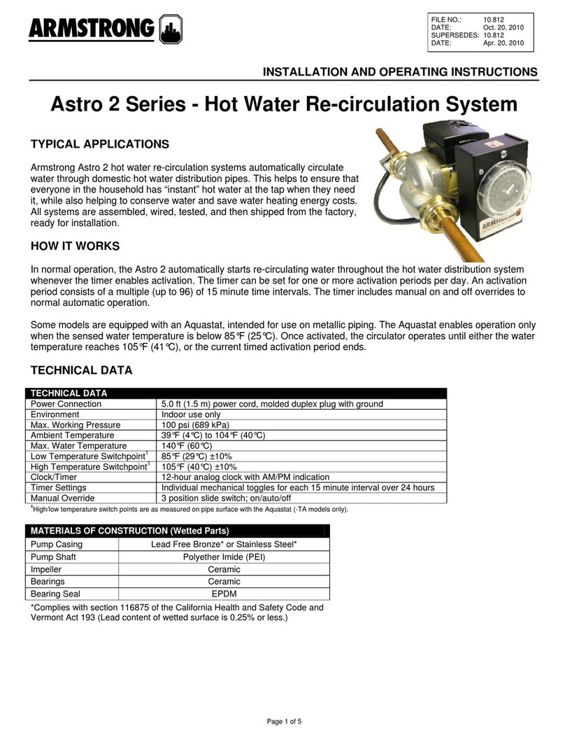
Armstrong Astro 2 Series User manual

Armstrong

Armstrong Astro 2 Series User manual

Armstrong 3760 Midi Series User manual

Armstrong

Armstrong 3760 Midi Series User manual

Armstrong 3760 Pro Series User manual

Armstrong

Armstrong 3760 Pro Series User manual

Armstrong E.2 Series User manual

Armstrong

Armstrong E.2 Series User manual

Armstrong 3760 ProDoseVDG Series User manual

Armstrong

Armstrong 3760 ProDoseVDG Series User manual

Armstrong 3760 Pro Series User manual

Armstrong

Armstrong 3760 Pro Series User manual

Armstrong ASTRO 2 SERIES User manual

Armstrong

Armstrong ASTRO 2 SERIES User manual

Armstrong ASTRO User manual

Armstrong

Armstrong ASTRO User manual

Armstrong E.2 Series User manual

Armstrong

Armstrong E.2 Series User manual

Armstrong AGEplus Series User manual

Armstrong

Armstrong AGEplus Series User manual

Armstrong AGE4 User manual

Armstrong

Armstrong AGE4 User manual

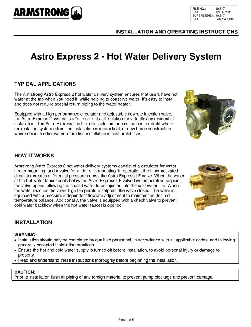
Armstrong Astro Express 2 User manual

Armstrong

Armstrong Astro Express 2 User manual

Popular Water System manuals by other brands

Rotek RA Series user manual

Rotek

Rotek RA Series user manual

Uponor WehoPuts Series Installation and operation manual

Uponor

Uponor WehoPuts Series Installation and operation manual

Watts GTS350C Installation, operation and maintenance manual

Watts

Watts GTS350C Installation, operation and maintenance manual

Reflex Servitec 35 Original operating manual

Reflex

Reflex Servitec 35 Original operating manual

Waterline Technology AlwaysFresh LF-1250 Installation options

Waterline Technology

Waterline Technology AlwaysFresh LF-1250 Installation options

Pentair SIATA V132 SFE-EV VIRIDION user manual

Pentair

Pentair SIATA V132 SFE-EV VIRIDION user manual

Thetford Tecma Sanisplit NK Operation & installation manual

Thetford

Thetford Tecma Sanisplit NK Operation & installation manual

Stuart Turner Mainsboost Plus Installation, operation & maintenance instructions

Stuart Turner

Stuart Turner Mainsboost Plus Installation, operation & maintenance instructions

Oase ProfiClear Premium TF-XL operating instructions

Oase

Oase ProfiClear Premium TF-XL operating instructions

Spectra Watermakers Cape Horn Extreme 330R Installation and operating manual

Spectra Watermakers

Spectra Watermakers Cape Horn Extreme 330R Installation and operating manual

Everpure ScaleKleen EV9655-00 Installation and operation guide

Everpure

Everpure ScaleKleen EV9655-00 Installation and operation guide

Judo JUKO-LF Installation and operating instructions

Judo

Judo JUKO-LF Installation and operating instructions

Elkay SOFT SIDES EZWS-EDFP217K Installation & use manual

Elkay

Elkay SOFT SIDES EZWS-EDFP217K Installation & use manual

AIO 2510-SXT Installation & start?up guide

AIO

AIO 2510-SXT Installation & start?up guide

Aquion Micro Budget owner's manual

Aquion

Aquion Micro Budget owner's manual

FlexiTank AutoPot 100L Assembly instructions

FlexiTank

FlexiTank AutoPot 100L Assembly instructions

NatureWater 63920 operating instructions

NatureWater

NatureWater 63920 operating instructions

Pelican Advantage Series owner's manual

Pelican

Pelican Advantage Series owner's manual

manuals.online logo
manuals.online logoBrands
  • About & Mission
  • Contact us
  • Privacy Policy
  • Terms and Conditions

Copyright 2025 Manuals.Online. All Rights Reserved.