PREOPERATION
PROCEDURES
PREPARATION FOR INITIAL USE
Each unit as shipped has no special unpacking or assembly
requirements prior to usage. Inspection to assure the unit
was not damaged in shipping and does not contain packing
debris is all that is required. After installation of a grinding
wheel a unit may be put to use.
CHECK HYDRAULIC POWER SOURCE
1. Usinga calibrated flowmeter and pressure gauge,check
thatthehydraulicpowersourcedevelopsaflowof 7-10 gpm/
26-38lpmat1500-2000psi/105-140bar.
2. Make certain the hydraulic power source is equipped with
areliefvalvesettoopen at 2100-2250 psi/145-155 bar
minimum.
3. Check that the hydraulic circuit matches the tool for
open-center(OC)orclosed-center (CC) operation.
CHECK TOOL
1. Make sure all tool accessories are correctly installed.
Failure to install tool accessories properly can result in
damage to the tool or personal injury.
2. There should be no signs of leaks.
3. The tool should be clean, with all fittings and fasteners
tight.
CHECK TRIGGER MECHANISM
1. Check that the trigger operates smoothly and is free to
travelbetweenthe "ON" and "OFF" positions.
CHECK GUARD ASSEMBLY
1. Inspect the wheel guard assembly for cracks and other
structuraldamage.
INSTALLINGANDREMOVINGGRINDINGWHEELS
READANDBECOMEFAMILIARWITHTHE SECTIONSIN
THISMANUALON SAFETYPRECAUTIONS,TOOLSTICK-
ERSANDTAGS, HYDRAULICHOSEREQUIREMENTS,
HYDRAULICREQUIREMENTS,ANDPREOPERATION
PROCEDURESBEFOREUSINGTHISPRODUCT.
OPERATION
NOTE:
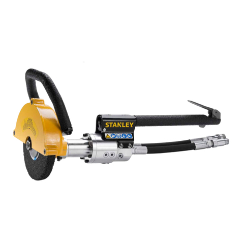
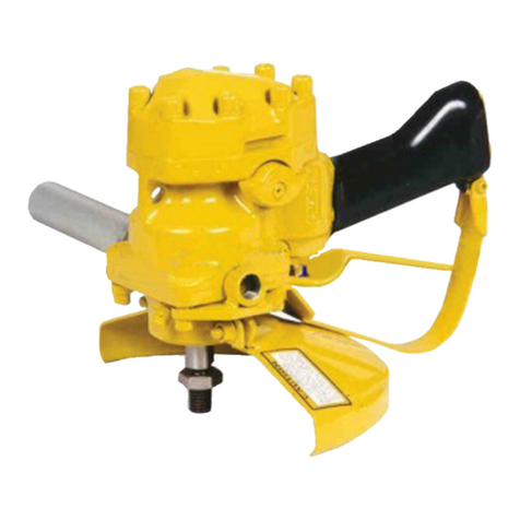
Use 8 inch by 1 inch thick (Type 1) grinding wheels with a
5/8 arbor hole. Only use grinding wheels which comply
with ANSI B7.1/ISO 525, 603.
1. Loosen 3 capscrews and lockwashers (64 & 63) and
removetheguardfrontplate(62)andsetaside.
2. Depress the push lock (45) to lock the spindle. Unscrew
thejamnut(61). Remove the outside flange (60).
3. Make sure blotters or labels remain on the grinding
wheel. Installthegrinding wheel onto the spindle (33) and
reinstall the outside flange and jam nut.
4. Depress the push lock and tighten the jam nut. Only
tightensufficientlytopreventslippageofthewheelbetween
theflanges.
5. Reinstall the guard front plate, capscrews and
lockwashers.
CONNECT HOSES
1. Wipe all hose couplers with a clean lint-free cloth before
makingconnections.
2. Connect the hoses from the hydraulic power source to
the hose couplers on the grinder. It is a good practice to
connect the return hose first and disconnect it last to
minimizeoravoidtrappedpressurewithinthegrindermotor.
3. Observe flow indicators stamped on hose couplers to be
sure that oil will flow in the proper direction. The female
coupler is the inlet coupler.
NOTE:
The pressure increase in uncoupled hoses left in the sun
may result in making them difficult to connect. When
possible, connect the free ends of operating hoses to-
gether.
OPERATING PROCEDURES
1. Observeallsafety precautions.
2. Always start the grinder with the grinding wheel or cone
awayfromtheworksurface.
3. Move the hydraulic circuit control valve to the "ON"
position.
10

