Aromat Cafe D420 User manual

1
D420 Service Manual
Service Manual
D420
Coffee Dispenser

2
Notice
Every effort has been made to ensure that the information contained in this document is up to
date and correct. However, neither the author, the publisher nor the manufacturer will accept
liability for any loss or damage caused resulting from any errors in or omissions of information
contained in this document.
This document may not be copied without the permission of DASS Manufacturing Ltd.
Document Change History
Issue Status Date
010 Draft1 30/05/06
020 Draft 2 05/06/06
030 1st Publlished 06/06/06
040 2nd Publ/d 26/06/06
Conventions Used in this Document
All instructions are given as viewed from the front of the machine.
Descriptions of the components referred to mostly match those used in the Illustrated
Parts Catalogue.
There are no bolts used in the construction of the machine. Hexagon headed screws are
referred to as Set Screws.
DASS Manufacturing Ltd.
SBC House, Restmor Way, Wallington, Surrey, SM6 7AH, United Kingdom.
Tel: +44 (0)20 8669 8012 Fax: +44 (0)20 8669 9529
Email: [email protected] Web: www.aromat-uk.com
© Copyright 2006, DASS Manufacturing Ltd. All rights reserved
Document No: TD D420 03 001

3
D420 Service Manual
Table of Contents
1 Introduction 5
1.1 Using this Manual 5
1.2 Understanding Fault Codes 6
1.3 The Control Panel 6
1.4 Setup Mode 7
1.5 Machine Supplied User Settings 7
2 Engineer Configurable Settings 8
2.1 Making Changes 8
2.2 Putting the D420 into Engineer Setup mode 8
2.3 The Engineer Menu Structure 9
2.4 Machine Supplied Settings 9
3 Obtaining Replacement Parts 10
3.1 Illustrated Parts Catalogue 10
3.2 Using Web Site 10
3.3 Obtaining User name and Password 10
3.4 Locating Part Illustration, Description and Number 10
3.5 On-line Parts Enquiry Form 10
3.6 Exploded View Assembly Drawing 10
4 Preparing the D420 for Servicing 11
4.1 Preparing a Suitable Work Area 11
4.2 Noting Machine Settings 11
4.3 Removing the Casing Panels 12
4.4 Refitting the Casing Panels 12
4.5 Disconnecting / Reconnecting Power Supply 13
4.6 Disconnecting / Reconnecting Water Supply 14
4.7 Draining the Tank 14
4.8 Draining Water Inlet Hose Pipe 15
5 Servicing Tank and Water Supply 16
5.1 Replacing the Water Inlet valve 16
5.2 Replacing Water Outlet Valves 16
5.3 Setting Water Outlet Valve Flow Rate 17
5.4 Replacing Heating Elements 19
5.5 Replacing Boiler Temperature Control Thermister 21
5.6 Calibrating the Thermister 21
5.7 Replacing Boiler Over Temperature Thermostat 23
5.8 Replacing a Float Microswitch 23
5.9 De-scaling the Tank 24
5.10 Cleaning Water Outlet Valves 25

4
6 Servicing Control Panel 27
6.1 Removing / Refitting Control Unit Assembly 27
6.2 Updating the PCB Processor Chip 27
6.3 Replacing the Control PCB 29
6.4 Replacing Set Up or Prime/Flush Membranes 29
6.5 Replacing the Display Unit 30
7 Servicing the Cooler Unit 32
7.1 Removing / Refitting Cooler Unit 32
7.2 Checking Product Detect System 32
7.3 Checking for Channel Changeover 33
7.4 Replacing Peristaltic Pumps 36
7.5 Adjusting a Peristaltic Pump 37
7.6 Replacing Heat Pump 39
8 Servicing the Power Supply Unit 40
8.1 Removing / Refitting PSU 40
8.2 Removing / Refitting PSU Cover Panels 41
8.3 Replacing a Relay or the Contactor 42
8.4 Replacing the Switched Mode PSUs 43
8.5 Replacing the PSU PCB 44
9 Technical Specifications 46
9.1 General Specifications 46
9.2 Main Looms Diagram 47
9.3 The Control PCB 48
9.4 PSU wiring diagram 49
Appendices
A Calibrating a Suitable Container 50
B Recommended List of Tools 51
C Machine Settings Form 52
D Cleaning and Sanitising Instructions 53
E PSU front Cover Label 54
5
D420 Service Manual
1 Introduction
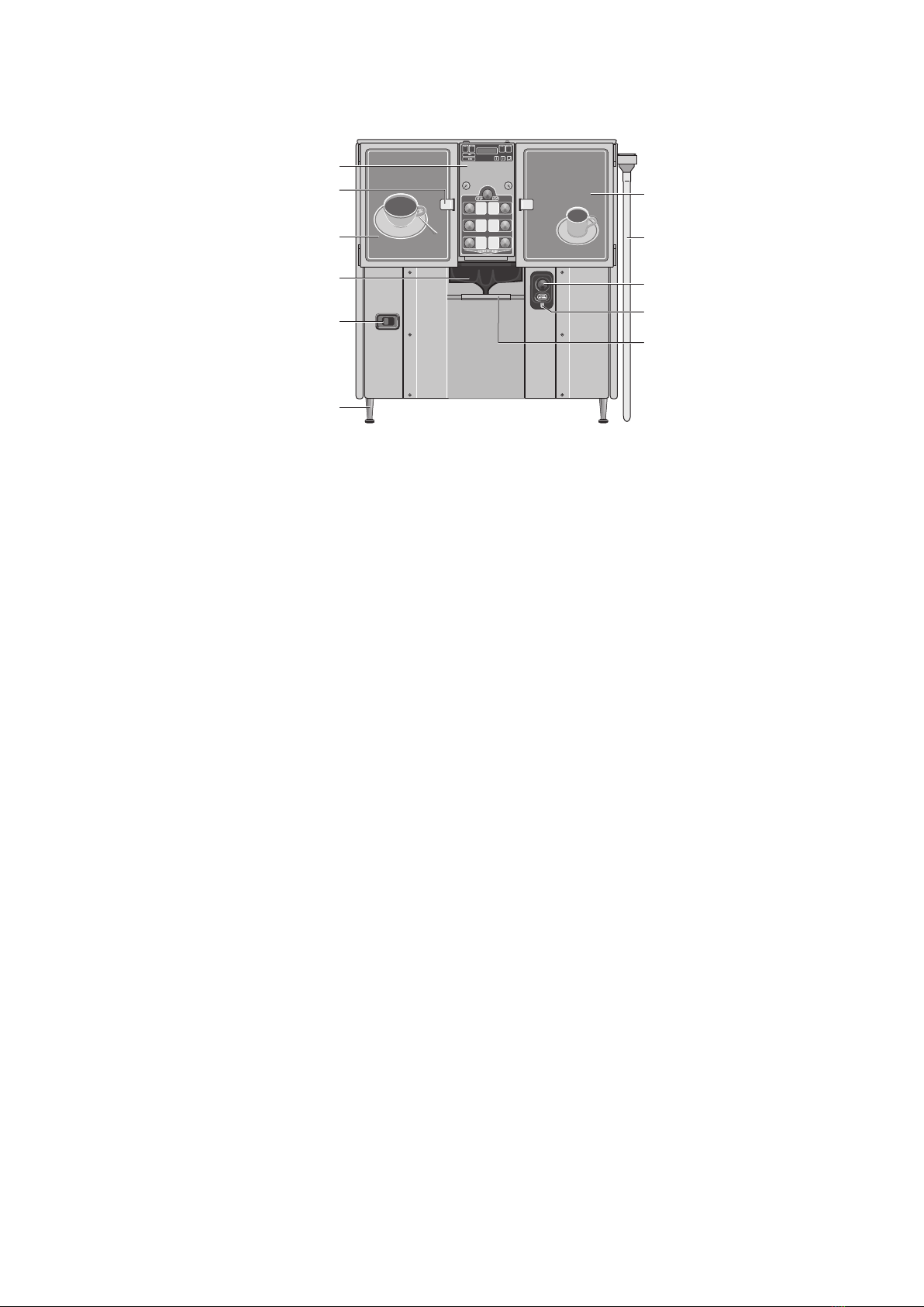
1 2 3 4
Coffee at its Finest ...
Dispense Extension Hose
Mounting Plate
Control Panel
Door LatchRH Cooler Unit Door
Dispense Extension Hose
Hot Water Only Button
LH Cooler Unit Door
Coffee Mixing Chamber
and Coffee Nozzle
Power ON / OFF switch
Adjustable Leg
Hot Water Nozzle
The D420 Coffee Dispenser requires minimal maintenance. The selection of procedures listed
in this document is based on the service requirement history of other machines produced by
DML.
To attain the highest levels of quality and reliability, the D420 will undergo continuous design
development during its life cycle. This document will therefore be updated regularly to reflect
any changes.
WARNING: Before replacing any major component, it is essential that the machine is
isolated from both the power and water supply.
1.1 Using this Manual
This manual describes the processes for the machine’s operation, how to obtain
replacement parts and instructions for carrying out the most probable maintenance
procedures.
In order to avoid the repetition of basic tasks, the document has been carefully sectioned
to enable the service engineer to extract the relevant sub sections for reference when on
site.
It is designed to be updated on a regular basis and will not be published in hard copy,
although a pdf version will be available for downloading from the DASS Technical Web
Site. Before carrying out any maintenance on the machine, the service engineer should
consult the web site and either download the latest pdf version of the entire document or
print off the relevant individual (html) web pages.
To identify the parts referred to in this manual, you may find it useful to view the D420
Illustrated Parts Catalogue, available from the web site.
As this manual is under constant review and development, any comments or advice from
service engineers that would improve the document would be welcomed. Please email
any comments to [email protected].

6
1.2 Understanding Fault Codes
The table below describes the D420’s Fault Codes:
Fault Description / Cause
Overflow Too much water in tank
Float Fault Logical fault. Overflow detected but insufficient water in
tank. Possible stuck float or faulty switch.
Thermostat Trip Thermostat has detected boiler overheat. Possible faulty
thermostat.
Possible Leak Actual leak or there has been no dispenses over 15 boiler
refills. This can occur due to evaporation in the tank.
Lack of Water During normal operation after machine has filled for the
first time, the inlet valve has been open for more than 15
minutes. Possible main water valve closed, low water
pressure or faulty inlet valve.
Lack of Water #1 The initial water fill from empty has taken longer than 25
minutes. Possible inadequate water flow or pressure.
Water overheat Thermister has detected water is too hot. Tank water
temperature is higher than top temperature setting.
Possible faulty thermister.
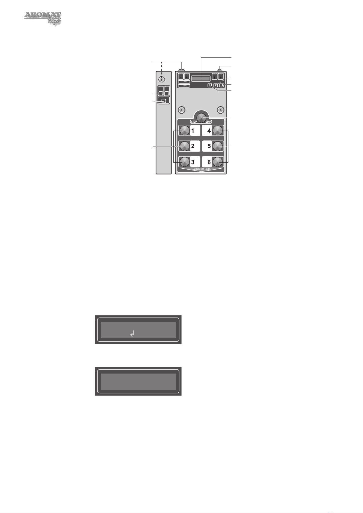
1.3 The Control Panel
12
1
PRIME PRIME
FLUSH
2
34
3
PRIME PRIME
FLUSH
4
Standby Mode switch
Display Panel
Product Low warning lamp
Mode keyswitch
SERVICE warning lamp
Product Channel PRIME button
Boiler Valve FLUSH button Boiler Valve FLUSH button
Product Select buttons Product Select buttons
LH Cooler door lock
Machine READY lamp Down button
Enter button
Up button
RH Cooler door lock
STOP button
O
I
Note: On some earlier models, the Mode keyswitch is located on the top left side of the
control panel and the Standby rocker switch is located on the top right side of the control
panel. It may be necessary to open the cooler unit doors to access these switches.

7
D420 Service Manual
1.4 Setup Mode
To view the user settings, put the machine into SETUP MODE by turning the Mode
keyswitch.
SETUP MODE
Press Selection
The menu options are:
• Selection
• Speed
• Strength
• Set Channel?
Scroll through the options by pressing the Enter button.
1.5 Machine Supplied User Settings
The machine was configured in the factory with the following user settings:
Button No. Speed Volume Strength Channels
1 3 10 gal 40:1 1&2
23 5 gal 40:1 1&2
32 Airpot 40:1 1&2
43 10 gal 40:1 3&4
53 5 gal 40:1 3&4
62 Airpot 40:1 3&4
The strength ratio means that 1 part of coffee concentrate is added to 40 parts of water.
Note: These settings may have been changed by the Installation Engineer to suit the
customer’s requirements.
8
2 Engineer Configurable Settings
1 2
1
PRIME PRIME
FLUSH
2
3 4
Standby Mode switch
Display Panel
Mode keyswitch
Product Channel PRIME buttons
Product Select buttons Product Select buttons
Down button
Enter button
Up button
STOP button
Boiler Valve FLUSH button
Note: On some models, the Mode keyswitch is located on the top left side of the control panel
and the Standby Mode Switch is located on the top right hand side of the control panel. It may
be necessary to open the cooler unit doors to access these switches.
2.1 Making Changes
DASS Manufacturing Ltd. will not accept liability for any damage or losses caused as a
direct result of any changes made to the machine by the service engineer when carrying
out any of the procedures described in this manual. All replacement parts used in the
D420 dispenser should be approved by DASS Manufacturing Ltd.
2.2 Putting the D420 into Engineer Setup mode
1 Turn the Mode keyswitch to put the machine into SETUP MODE.
2 Press PRIME 1 and then PRIME 2; the following will display:
ENGINEER SETUP
Press
3 Press the Enter button. The display will change to:
Temp Display
Fahrenheit
Scroll through the menu by pressing the Enter button.

9
D420 Service Manual
2.3 The Engineer Menu Structure
In ENGINEER SETUP mode, the following settings may be changed:
• Temperature Display
• Maximum Temperature
• Enable / Disable Coffee
• Enable / Disable Water
• Product Choices
• Peris Speed Offset
• Enable / Disable product Sensors
• Enable / Disable Leak Detect
The D420 Installation Guide provides basic instructions for changing these settings.
2.4 Machine Supplied Settings
The machine was configured in the factory with the following user settings:
Temp Display Fahrenheit (USA) or Celsius (EU)
Set Max Temperature=194F or 95C
Coffee Enabled
Water Enabled
Product Choices 2 + 2
Product Sensors Enabled
Leak Detect Enabled
Note: Peris Speed Offsets will differ between machine and pumps.
Note: These settings may have been changed by the Installation Engineer to suit the
customer’s requirements.

10
3 Obtaining Replacement Parts
3.1 Illustrated Parts Catalogue
A printable illustrated parts catalogue can be downloaded from the PDF Bank on the
Aromat Technical Website.
3.2 Using Web Site
To access the technical website go to: www.aromat-info.com and click on Technical
Documents. This will take you to the Technical Centre which is in both English and
German. A Username and Password is required to enter the site.
3.3 Obtaining User name and Password
Complete and send the on-line Registration Form or send an email to:
3.4 Locating Part Illustration, Description and Number
Select Parts Lists from the left menu and then D420 at the top of the Navigation page.
Select the version to reach the Parts Lists overview page. Clicking on an assembly
image will open a new window with an annotated exploded view of that assembly.
Clicking on the assembly menu will take you to the relevant section in the parts list.
Parts Lists Overview Page
3.5 On-line Parts Enquiry Form
Having located the part, selecting Parts Enquiry from the left hand menu will open a new
window with an on-line form. Complete the form and press SEND. A representative of
DASS Manufacturing Ltd. will get back to you with prices and availability of parts as soon
as possible.
3.6 Exploded View Assembly Drawing
A printable composite exploded view of the D420 assembly can be downloaded from the
PDF Bank on the Aromat Technical Website.

11
D420 Service Manual
4 Preparing the D420 for Servicing
WARNING: To avoid electric shock, when the casing panels are being removed, the
D420 MUST is isolated from the mains power supply.
Note: Unless essential for any work being carried out, we recommend that the valve for the
mains water service to the machine also be closed before servicing the D420.
4.1 Preparing a Suitable Work Area
Many components of the D420 Coffee Dispenser can be serviced or replaced in-situ but
where main assemblies need to be removed from the machine, we recommend that a
work area or temporary mobile work bench be set up adjacent to the machine. Ideally,
this work area should not be less than 10 square feet (1 square metre).
For most service procedures, only the lower front panel or top panel needs to be
removed. Space is required for temporary storage of these panels.
All tools required should be to hand before undertaking any major dissembling.
4.2 Noting Machine Settings
Before undertaking any maintenance on the D420, noting down all of the current user and
engineering mode settings will enable you to return the machine to service exactly as the
original settings.
Note: It will be necessary to change the dispense volume settings for one or more of the
product selection buttons when undertaking some maintenance procedures. These may
need to be reset with the customer present on completion of the work.
The User Settings to note for each Product Select Button are:
• Selection (Enabled or Disabled).
• Selection size (Speed = 1, 2 or 3).
• Dispense Volume (This will need to be measured if the information cannot be
supplied by the customer - see note below)
• Selection strength (water:coffee ratio).
• Set channel (1, 2, 3, 4 ; 1, 2 &3 ; 1 & 2 or 3 & 4 depending on the option
selected in Engineering Mode).
Note: To determine the dispense volumes, set the machine to Coffee Disabled and
undertake a dispense for each Product Select Button into the largest typical container
used by the customer and then measure.
The Engineering Mode settings to note are:
• Temperature Display (Celsius, Fahrenheit, None).
• Maximum Temperature Set.
• Product Choices (4 Identical, 3+1, 2+2 or 4 Different).
• Peris Speed Offset for each pump.
• Leak Detect (Enabled or Disabled)
A Machine Settings Form is included in Appendix C of this manual; also available as a
printable pdf document from the DASS technical web site (d420_machine_settings.pdf).

12
4.3 Removing the Casing Panels
WARNING: Before removing any of the Casing Panels the machine MUST be
isolated from the mains power supply.
Note: The machine should only be powered ON with the panels removed if the engineer
can satisfy himself that it is safe to do so.
Tools required:
No. 2 Pozidrive Screwdriver
No. 2 Pozidrive Screwdriver – Stubby
To remove the casing panels:
1 Power OFF and isolate the machine from the mains power supply.
2 Open both Cooler Unit doors and remove the four M4 x 8mm screws securing the
casing Front Panel.
3 Remove the Front Panel by tilting toward you to clear the On/Off switch and Hot
Water button and lifting slightly to clear the support lugs at the front of the Chassis
Base Plate.
4 With both Cooler Unit doors still open, remove the four M4 x 8mm screws securing
the Casing Top Cover.
5 Remove the Casing Top Cover by lifting up and toward the front.
6 Remove the two screws securing the Cooler Units to the Cooler and Nozzle
Platform and slide the Cooler units forward about one inch (25mm).
7 Undo the twelve M4 x 8mm screws securing the RH Side Panel, first at the top,
then at the base and then at the back.
8 Ease the RH side panel out at the back and bottom.
9 Remove the bottom three and loosen the top M4 x 8mm screws securing the LH
side panel to the Back Panel.
10 Remove the five screws securing the Back Panel to the chassis Base Plate,
supporting the panel at the bottom.
11 Still supporting the Back Panel at the bottom, remove the remaining Side Panel
fixing screw and slide the back panel out.
12 Undo the eight remaining screws securing the top and bottom of the LH side panel.
13 Ease the LH side panel out at the back and bottom.
4.4 Refitting the Casing Panels
WARNING: Before refitting any of the Casing Panels the machine MUST be
isolated from the mains power supply.
Tools required:
No. 2 Pozidrive Screwdriver
No. 2 Pozidrive Screwdriver – Stubby
To refit the casing panels:
1 Power OFF and isolate the machine from the mains power supply.
2 First refit the Back Panel by loose fitting the five screws securing it to the chassis
Base Plate.
13
D420 Service Manual
3 Slide both Cooler Units forward about one inch (25mm).
4 Refit both Side Panels by easing the lip on the top and bottom of the panels
around the chassis Side Frames and fits on the outside of the Back Panel.
5 Loose fit the screws securing the Side Panels to the Back Panel.
6 Loose fit the screws securing the Side Panels to the top of the chassis Side Frame
and Tank.
7 Tight fit the screws securing the Side Panels to the chassis Base Plate.
8 Tighten all loosely fitted screws.
The Cooler Units may now be slid back into place and secured.
The Top Panel and Front Panel are reinstalled by reversing the instructions given in
Section 4.3.
4.5 Disconnecting / Reconnecting Power Supply
WARNING: Before removing the PSU Front Panel, the Mains Power Supply MUST
be switched OFF and the cable unplugged or disconnected from the supply.
Note: This procedure MUST be carried out by a qualified Electrician. Refer to the
instructions on the PSU Front Panel. See copy in Appendix E of this document.
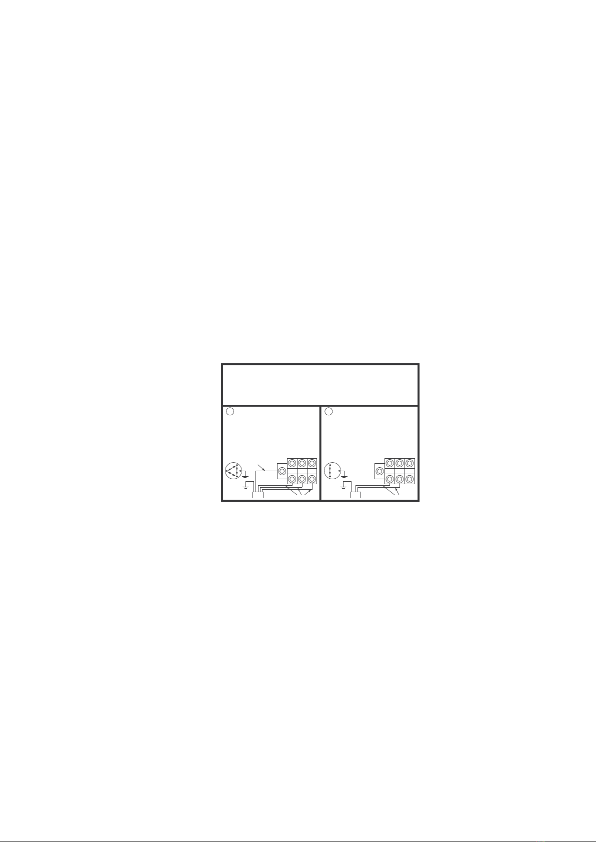
ELECTRICAL INSTALLATION INSTRUCTIONS
TO BE CARRIED OUT BY TRAINED ENGINEERS ONLY
1. Establish the supply power available at
the machine location.
If 3 phase then follow column A.
If single phase, follow column B.
2. Ensure that the machine connection
cable uses copper wires only and is
approved for the supply voltage and
current fuse rating of the supply outlet.
3. Ensure the EARTH connection is
securely made, check continuity to site
earth.
A 3 PHASE DELTA
THIS MACHINE WILL AUTO-SENSE 200V TO 480V
IF V = 440V - 480V THEN 60AMP / PHASE SUPPLY REQUIRED
IF V = 300V - 440V THEN 50AMP / PHASE SUPPLY REQUIRED
IF V = 235V - 265V THEN 60AMP / PHASE SUPPLY REQUIRED*
IF V = 200V - 235V THEN 50AMP / PHASE SUPPLY REQUIRED*
* IF MAX SUPPLY IS 30 AMPS THEN SELECT THE “LOW CURRENT”
SWITCH LOCATED TO THE RIGHT OF THE RED ON/OFF SWITCH. IF
SUPPLY CURRENT IS LESS THAN 30 AMPS THEN MACHINE IS NOT
SUITABLE FOR 3 PHASE DELTA, HOWEVER IT MAY BE SUITABLE IF
WIRED FOR SINGLE PHASE - SEE COLUMN ‘B’
V
V
E
V
L1
COMMON / NEUTRAL
(IF SUPPLIED)
EARTH
SUPPLY CONDUCTORS
L2 L3
N
B SINGLE PHASE
THIS MACHINE WILL AUTO-SENSE 200V TO 255V
IF V IS LESS THAN 200V THEN MACHINE IS NOT SUITABLE.
50 AMP SUPPLY IS REQUIRED. IF MAX SUPPLY IS 25 AMPS THEN
SELECT THE “LOW CURRENT” SWITCH LOCATED TO THE
RIGHT OF THE RED ON/OFF SWITCH.
IF SUPPLY CURRENT IS LESS THAN 25 AMPS THEN MACHINE IS
NOT SUITABLE.
V
EL1
EARTH
SUPPLY CONDUCTORS
L2 L3
N
REPLACE THIS COVER BEFORE APPLYING POWER TO THE MACHINE
Tools required:
No. 2 Pozidrive Screwdriver
8mm AF socket
10mm AF socket
Socket holder
Gland Spanners
To disconnect the D420 from the Mains Power Supply:
1 Power OFF and isolate the machine from the Mains Power Supply.
2 Remove the Front Panel as described in Section 4.3.
3 Undo the four M4 x 12mm screws and remove the PSU Connection Cover.
4 Disconnect the Mains power and earth cables from the Terminal Blocks.
5 Undo the cable gland-securing nut and pull the cable and cable gland down
through the Conduit Plate and Base Plate.
Reconnect the Power Supply by reversing the above instructions.
Note: Ensure PSU Front Panel is refitted before re-connecting to mains power supply.
14
4.6 Disconnecting / Reconnecting Water Supply
Note: When machine is powered OFF, water will not flow through the inlet valve.
Tools required:
1 1/8” AF Spanner
To disconnect the dispenser from the Mains Water Supply:
1 Ensure that the mains valve is closed.
2 Place a bucket or suitable container beneath the mains valve.
3 Disconnect the flexible inlet connector pipe from the mains valve and allow the
water in the hose to run into the container. Retain the sealing washer.
4 If necessary, disconnect the flexible inlet connector pipe from the inlet valve under
the Base Plate, retaining the sealing washer.
The water supply is reconnected by reversing the instructions above.
4.7 Draining the Tank
WARNING: Water in the tank may scold.
Note: When the D420 Dispenser is powered OFF, water will not flow through the Water
Inlet Valve. DO NOT shut off the water at the supply valve and leave the machine
powered ON, as this could damage the Water Inlet Valve.
Note: The tank capacity is 21 gallons (80 litres).
Tools required:
No. 2 Pozidrive Screwdriver
Large bucket
To drain the tank:
1 Power OFF and isolate the machine from the Mains Power Supply.
2 Remove the Front Panel as described in Section 4.3.
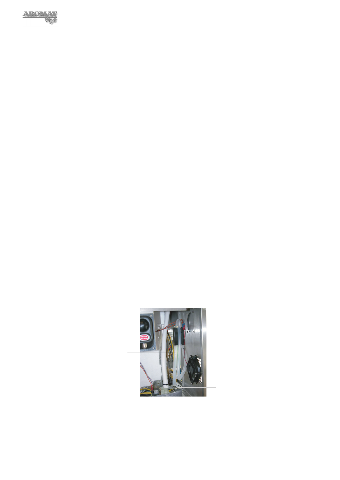
Drain Hose
Hose Clamp
3 Locate the drain hose and clamp, which is connected to the bottom right hand of
the tank, and remove the hose from its bracket on the chassis side panel.
4 Place the end of the drain hose over the bucket (or drain if available).
5 Open the hose clamp to allow water to pass. Close and reopen the clamp as
necessary until the tank is empty.

15
D420 Service Manual
4.8 Draining Water Inlet Hose Pipe
Even though the tank may be drained, water will still remain in the water inlet hose pipe.
Tools required:
Metal hose clamp (supplied with the machine)
One litre container
Towel or absorbent cloth
Side cutting pliers
Cable tie
To drain the water inlet hose pipe:
1 Power OFF and isolate the machine from the Mains Power Supply.
2 Remove the Front Panel as described in Section 4.3.
3 Place the metal hose clamp over the inlet hose near to the inlet valve.
4 Place the container near to the inlet valve.
5 Place a towel or absorbent cloth around the inlet valve.
6 Cut the black cable tie securing the hose to the inlet valve and disconnect the tube.
7 Place the end of the pipe over the container and open the metal hose clamp to
expel the water.
8 After completing the service work, refit the Water Inlet Hose Pipe by reversing the
above procedure.
Note: A new cable tie will be required to secure the hose.
16
5 Servicing Tank and Water Supply
5.1 Replacing the Water Inlet valve
Note: It is not necessary to drain the water tank to replace the Water Inlet Valve.
Tools required:
Metal hose clamp (supplied with the machine)
1 1/8” AF Spanner
No. 2 Pozidrive Screwdriver – Stubby
To replace the water inlet valve:
1 Power OFF and isolate the machine from the Mains Power Supply.
2 Remove the lower Front Panel as described in Section 4.3.
3 Close the mains water valve.
4 Disconnect from the mains water supply as described in Section 4.6.
5 Drain the Water Inlet Pipe as described in Section 4.8.
6 Place a towel or absorbent cloth on the bench underneath the Water Inlet Valve.
7 From underneath the chassis Base Plate, disconnect the Inlet Connector Pipe from
the Water Inlet Valve, being careful not to lose the fibre washer
8 From underneath the chassis Base Plate undo the two screws securing the Water
Inlet Valve.
9 Fit the new valve by reversing the above procedure.
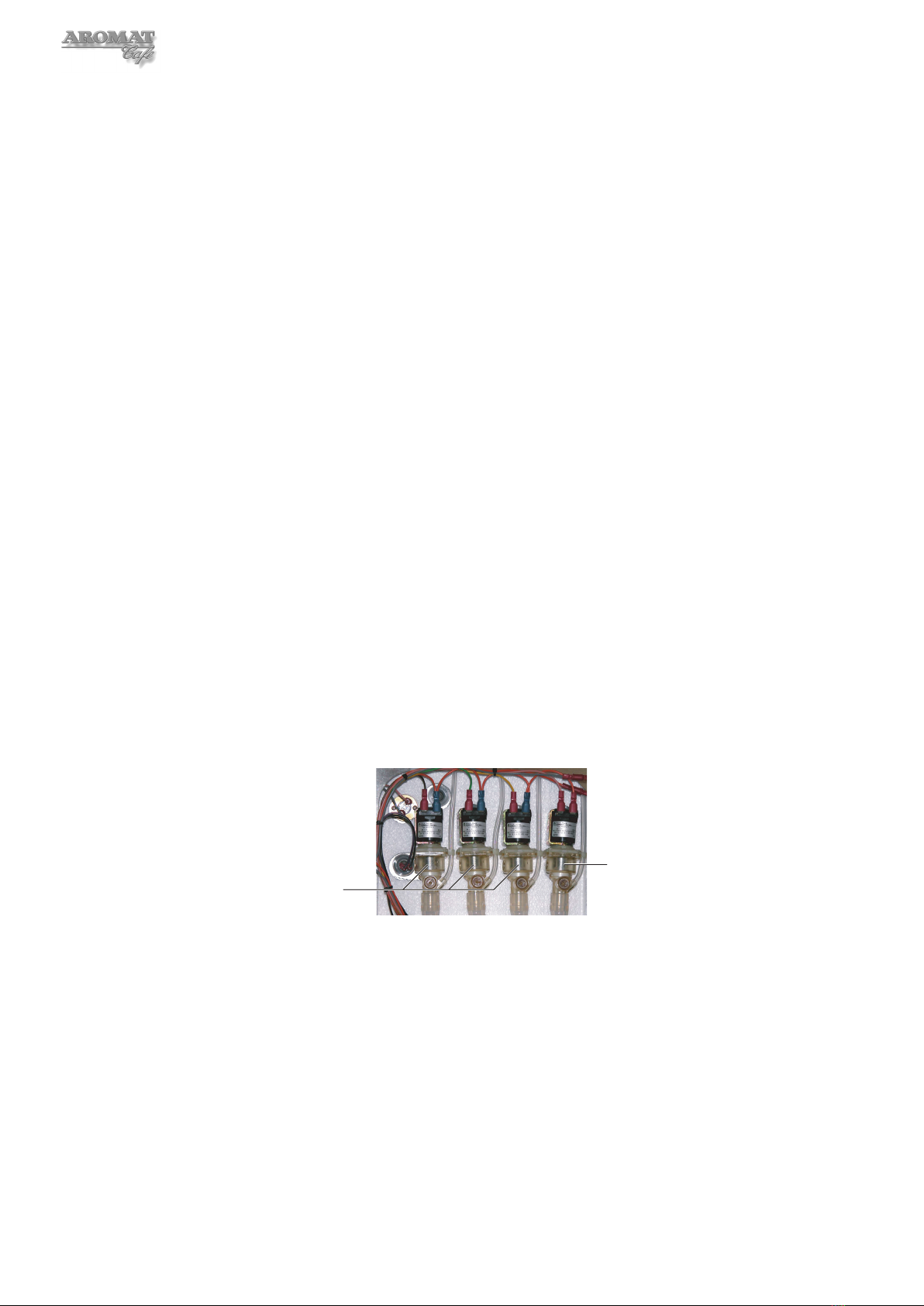
5.2 Replacing Water Outlet Valves
There are four Water Outlet Valves. Numbering them from the left, 1, 2, 3 and 4, the first
three dispense water for coffee and the fourth dispenses hot water only.
1 2 3 4
Hot Water Only
Water for Coffee
Note: The tank does not need to be fully drained but the water level must be below the
valve tube before removing the valve. One or both Cooler units should be removed.
Tools required:
No. 2 Pozidrive Screwdriver
To replace a Water Outlet Valve:
1 Power OFF and isolate the machine from the Mains Power Supply.
2 Remove the lower Front Panel as described in Section 4.3.
3 Remove either or both Cooler units as described in Section 7.1.
17
D420 Service Manual
4 Follow the procedure in Section 4.7 to lower the water level to below the valve
tube. As the water drains out, you should be able to see the top of the water in the
valve body as the level drops. Once this level appears to stop dropping, run off
another bucket of water to ensure that the level is below the valve.
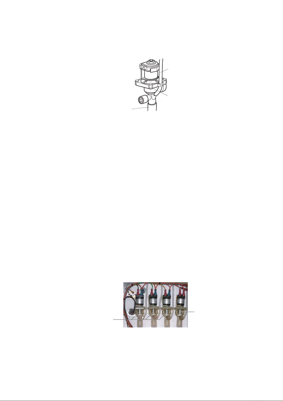
4mm
Silicone Tube
Outlet Tube
Valve
Body
5 Disconnect the 4mm silicone tube on the RH side of the valve.
6 Mark cables and disconnect the wiring to the valve solenoid.
7 Slightly rotate and carefully slide the valve out of the Boiler Seal.
8 Remove the valve complete with the outlet tube and elbow.
9 Carefully push the new valve into the Boiler Seal.
10 Fit the outlet tube and elbow from the old valve and reconnect the 4mm silicone
tube to the RH side of the valve.
Note: The flow rate for the new valve now has to be set. To do this, the machine must
be powered ON, the tank refilled and the water brought up to the maximum operating
temperature.
5.3 Setting Water Outlet Valve Flow Rate
The flow rate for each of the Water Outlet Valves will have been set to 5 litres per minute
in the factory. This setting is important to establishing comparable concentrate ratios for
each of the channels.
Note: The machine must be powered ON, the tank filled and brought up to maximum
operating temperature.
Note: This procedure may require changing the speed and channel settings. We
recommend that the customer’s settings are noted down as described in Section 4.2.
1 2 3 4
Hot Water Only
Water for Coffee
There are four Water Outlet Valves. Numbering them from the left, 1, 2, 3 and 4, the first
three dispense water for coffee and the fourth dispenses hot water only.
Which of the valves employed for dispensing water for coffee depends on the selection
speed and product channel, for the product selection button used.

18
Note: If all valves are being replaced, first adjust and set Outlet Valve 2, then Outlet
Valves 1 and 3.
Outlet Valve 4 uses the Hot Water Only button and for maximum flow, should be adjusted
so that the screw is flush with the cylinder face.
Tools required:
Calibrated 2 gallon (10 litre) container or bucket (see Appendix A)
Timer with second hand
6mm hexagonal key (or 6mm flat end screwdriver)
First prepare the machine:
1 Turn the mode keyswitch to put the machine into SETUP MODE.
2 Press PRIME1 and then PRIME2 to put the machine into ENGINEER SETUP.
3 Press the Enter button to scroll down until Coffee Enabled is displayed and press
the Down button to disable coffee.
4 Press the Enter button to scroll down until Product Choices is displayed and
select 2+2.
5 Place the calibrated container under the nozzle.
6 Press the Enter button to scroll down until SETUP MODE is displayed.
7 Press Product Select Button 1.
8 Press the Enter button to scroll down until Set Volume is displayed.
9 Press Product Select button 1, time the dispense for 60 seconds and press the
STOP button.
10 Press the Enter button to scroll until SETUP MODE is displayed again.
11 Remove either or both Cooler Units as described in section 7.1.
Adjustment
Screw
Valve
Body
To adjust the flow rate for Water Outlet Valve 1:
Note: If also replacing Outlet Valve 2, first adjust and set valve 2, then valve 1.
1 With the machine in SETUP MODE, press Product Select Button 1 and then the
Enter button to scroll down until Speed is displayed and set to Speed=2.
2 Press the Enter button to scroll down until Set Channel? is displayed and using
the Up and Down buttons, set to Ch 1&2.
3 Press the Enter button to scroll down until SETUP MODE is displayed again.
4 Turn the Mode keyswitch back to normal dispense.
5 Press Product Select Button 1. 10 litres should be dispensed.
6 If not, adjust the Water Outlet Valve by turning the screw one quarter of a turn each
time. Turn anticlockwise to increase the flow and clockwise to decrease the flow.

19
D420 Service Manual
7 Repeat the operations 5 and 6 until the correct amount (10 litres) is dispensed.
To adjust the flow rate for Water Outlet Valve 2:
1 With the machine in SETUP MODE, press Product Select Button 1 and then the
Enter button to scroll down until Speed is displayed and set to Speed=1.
2 Press the Enter button to scroll down until Set Channel? is displayed and using
the Up and Down buttons, set to Ch 1&2.
3 Press the Enter button to scroll down until SETUP MODE is displayed again.
4 Turn the Mode keyswitch back to normal dispense.
5 Press Product Select Button 1. 5 litres should be dispensed.
6 If not, adjust the Water Outlet Valve by turning the screw one quarter of a turn each
time. Turn anticlockwise to increase the flow and clockwise to decrease the flow.
7 Repeat the operations 5 and 6 until the correct amount (5 litres) is dispensed.
To adjust the flow rate for Water Outlet Valve 3:
Note: If also replacing Outlet Valve 2, first adjust and set valve 2, then valve 3.
1 With the machine in SETUP MODE, press Product Select Button 1 and then the
Enter button to scroll down until Speed is displayed and set to Speed=2.
2 Press the Enter button to scroll down until Set Channel? is displayed and using
the Up and Down buttons, set to Ch 3&4.
3 Press the Enter button to scroll down until SETUP MODE is displayed again.
4 Turn the Mode keyswitch back to normal dispense.
5 Press Product Select Button 1. 10 litres should be dispensed.
6 If not, adjust the Water Outlet Valve by turning the screw one quarter of a turn each
time. Turn anticlockwise to increase the flow and clockwise to decrease the flow.
7 Repeat the operations 5 and 6 until the correct amount (10 litres) is dispensed.
To put the machine back into service,
1 Reinstall the Cooler Unit and Front Panel.
2 Reset the machine to the customer’s settings as noted.
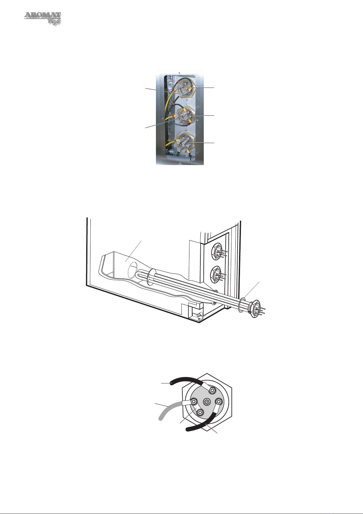
5.4 Replacing Heating Elements
An access panel has been provided on the RH side casing panel.
WARNING: The machine must be completely isolated from the Mains Power supply
when changing any electrical component.
Note: This procedure MUST be carried out by a qualified electrician.
Tools required:
No. 2 Pozidrive Screwdriver
8mm AF deep socket
75mm Element box spanner
To replace the heating element/s:
1 Power OFF and isolate the machine from the Mains Power Supply.
2 Remove the lower Front Panel as described in Section 4.3.
20
3 Drain the tank as described in Section 4.7.
4 Undo the eight M4 x 10mm countersunk screws and remove the Element Access
Cover fitted to the RH side casing panel.
Element 1
Element 2
Element 3
Link
Silicon
Sleeve
5 Tab and mark the cabling connected to the heater element to ensure they are
reconnected to the new element/s correctly.
6 Disconnect the cabling to the element/s, retaining the nuts, links and washers.
7 Unscrew the element/s and carefully extract.
Tank Bracing
Panel
‘O’ Ring
8 Fit the new element/s by reversing the above procedure, taking care to pass the
element through the tank bracing panel.
Note: Discard the element washer and replace with a new element washer or ‘O’
ring, or reuse the ‘O’ ring if one was originally supplied.
Black
Yellow
Link
Black
WARNING: Connect the links and cables as shown above. Incorrect wiring
will damage the element.
9 Connect to the Mains Power Supply and power ON the machine.
Table of contents
Popular Coffee Maker manuals by other brands


 quick start guide")


Beanrush Beverages
Beanrush Beverages MyEspressino instruction manual

Qbo
Qbo YOU-RISTA Descaling manual

Keurig
Keurig K2.0-300 series user guide

Wolf
Wolf Coffee System Use and care guide

LAVAZZA
LAVAZZA Blue LB2200 Instructions for installation and use

George Howell Coffee
George Howell Coffee AEROPRESS quick start guide