ARP Fridge Defend User manual

Fridge Defend® by ARP
v5.x ARP & ARP + Fan Control
Ancillary Graphical User Instructions
Please click here for Online ARP Video Operation Manual
User Web Search Engine:
Click Here for Web Search before Contacting ARP Control
WARNING: The operator of the ARP Control is responsible for knowing the status of the
control at all times, including the self-test functions. The ARP Control is designed to turn itself
on if a power interruption occurs. A power interruption can be as simple as using the RV
Master Power Switch to turn off power during storage of the RV. In this situation, when the
power is restored to the RV, the ARP Control will turn itself on incase the operator forgets to
check the control. The operator must perform the Test of ARP Relay described in this manual
before each outing to confirm function of the ARP Control. Also, brown outs and transient on
the RV 12VDC supply can turn off the ARP Control, these power interruptions are due to many
factors which go beyond the scope of this document to describe. Due to brown outs and
transients one needs to confirm that the ARP is functioning on a regular basis.
©2020 ARPC L.L.C. All rights reserved.

Terms -- Conditions & Contact Information
This manual is copyrighted © by ARPC L.L.C. 2013-2020. All rights are reserved. This manual may only be reproduced
with permission of ARPC L.L.C.. This manual is furnished for informational use only and is subject to change without
notice. This manual does not imply any commitment on the part of ARPC L.L.C. or its business partners. ARPC L.L.C.
and its business partners assume no responsibility or liability for any error or inaccuracies that may appear in this manual.
By use of this document for installation and operation of the ARP Control (Fridge Defend®), the user is agreeing to the
ARPC L.L.C. terms and conditions found in document ARPC LLC License Agreement.pdf. Also, the end user needs to
understand that the ARP Control can be turned off at any time, thereby removing the ARP Control function and reverting
to the operation of the refrigerator to its previous state. Also, the self-test functions which make the Fridge Defend an
accessory safety control may be turned off by the end user; this will defeat the 24 hour self-test. Power surges can turn off
the ARP Control just the same as any equipment in an RV, thus it is the operators responsibility to insure that the control
is functioning properly. Any ARP Control that is believed to be malfunctioning, the ARP Control must be removed from
operation and returned to ARPC L.L.C. for inspection immediately. Contact ARPC L.L.C. for shipping instructions. The
reason for return must be included in writing with the returned control; shipping is the responsibility of the end user to
and from ARPC L.L.C..
The document "ARPC LLC License Agreement.pdf" can be downloaded at web address
http://www.ARPrv.com
or, please send any request to e-mail address below, ARPC L.L.C. will supply information in a timely manner:
TABLE of CONTENTS
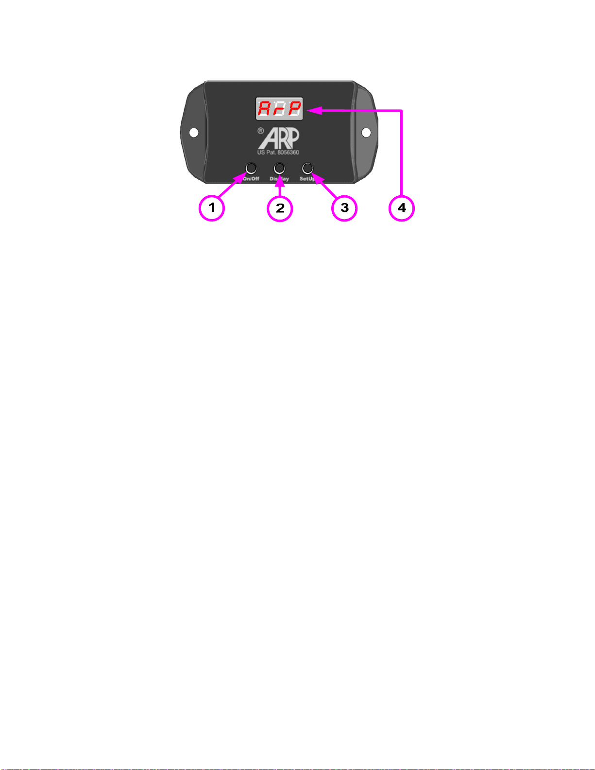
GRAPHICAL REFERENCE...................................................................................................... 3
INTRODUCTION....................................................................................................................... 4
BUTTON FUNCTION................................................................................................................ 4
ON/OFF BUTTON – Turn On/Off ARP Control....................................................................... 4
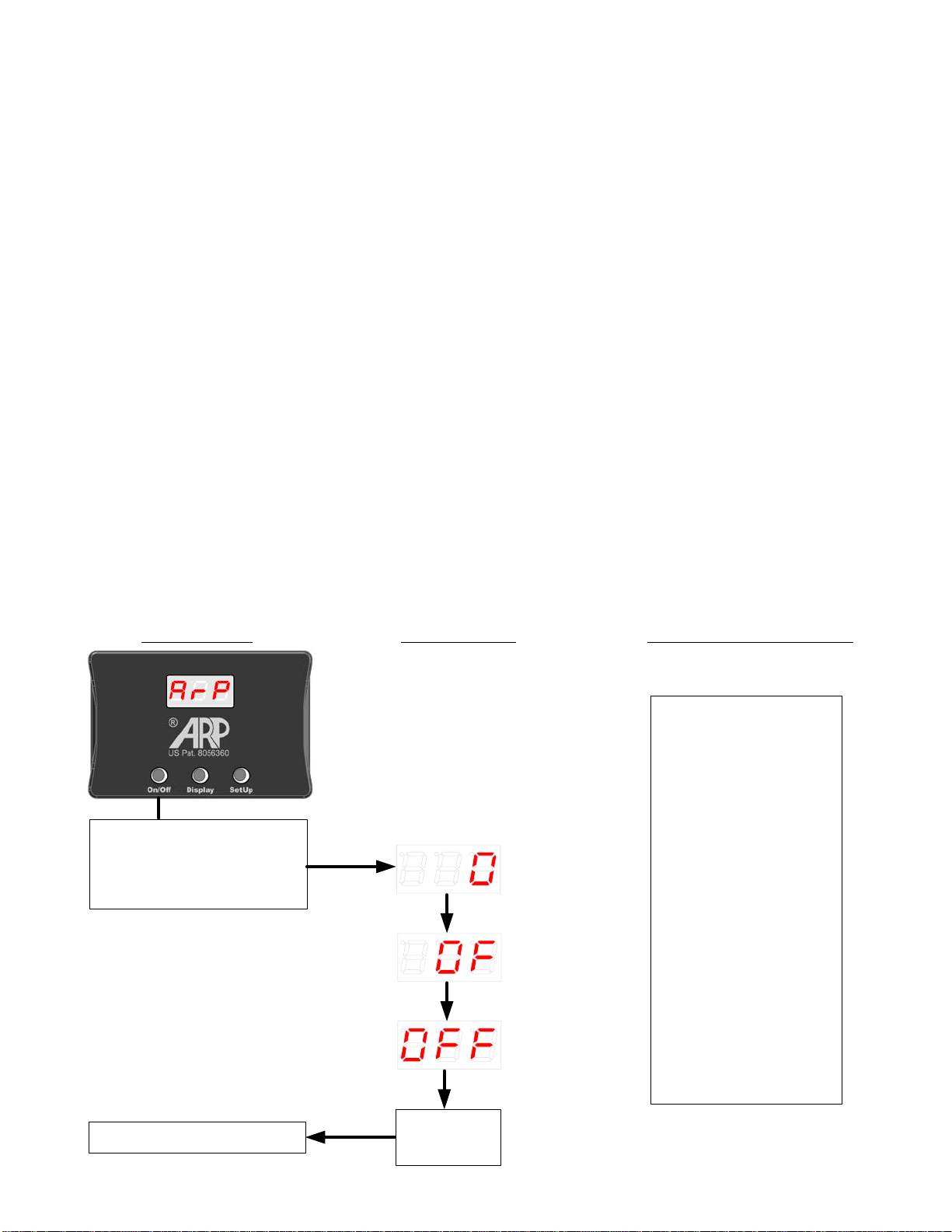
Turn OFF ARP Control in All Modes............................................................................... 4
! Important Information for Setting Control Modes.................................................. 5
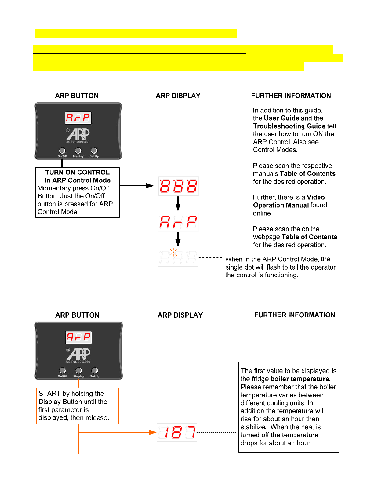
Turn ON Control in ARP Control Mode........................................................................... 5
ARP or SP0 Mode Display Button Function............................................................ 5
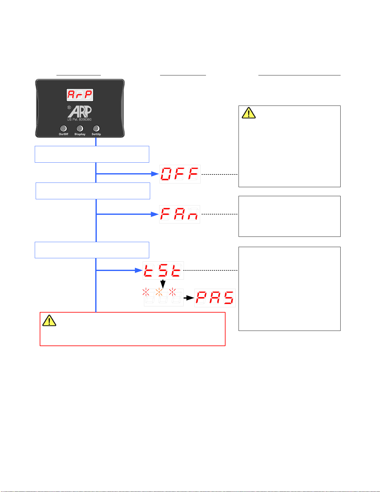
ARP or SP0 Mode SetUp Button Function.............................................................. 7
Turn ON Control in SP0 Mode......................................................................................... 8
SP0 Mode Troubleshooting Button Function................................................................. 8
Turn ON Control in Auto Tune Mode.............................................................................. 9
Turn ON Control in SetUp Mode.................................................................................... 10
☻Before Contacting ARP for Assistance ............................................................. 10
SETUP MODE NAVIGATION ................................................................................................. 11
Button Operation............................................................................................................ 11
Navigation Flow Diagram............................................................................................... 11
ERRORS and/or MISTAKES DURING SetUp SESSION....................................................... 15
Mistake During SetUp Session?.................................................................................... 15
What if I Make a Mistake and Save?.............................................................................. 16
©2020 ARPC L.L.C. All rights reserved.
How Do I Keep Track of Things?................................................................................... 16

ARP Control v5.x Graphical User Instructions 04/20/2020 ©ARPC L.L.C. All rights reserved. 3
GRAPHICAL REFERENCE
1: ON/OFF BUTTON
General Install Guide
1.6 ARP Control and your Refrigerator
ARP User Guide
BUTTON FUNCTION – Use this section to understand how to make changes
with the buttons.
1.1 Turn on ARP Control
1.11 Turn off ARP Control
1.12 Restore Factory Control
MODE FUNCTIONS – The ARP must be turned off to enter any of the
startup modes.
2.1 ARP Control Mode – See 2 & 3 below for other startup modes.
2: DISPLAY BUTTON
ARP User Guide
1.2 View Boiler Temperature
1.3 View Fan Temperature
2.2 No Set-Point Mode
3: SETUP BUTTON
General Install Guide
12.1 Testing ARP Install
ARP User Guide
1.5 Test ARP Relay
1.6 Test Fan Relay
1.7 Automated Test
2.3 Auto Tune Mode – This mode is very rarely used.
2.4 Setup Mode
Troubleshooting Guide
SETUP MODE – Be sure to store new settings before exiting SetUp Mode.
2.2 Types of SetUp Mode Variables
4: DISPLAY
ARP User Guide
1.8 ARP Protection Period
1.9 If *O*F*8 is Displayed – 5 Time Trigger Event
1.10 If *H*O*8 is Displayed – Excessive Overheat Condition
Troubleshooting Guide
ARP ERROR MESSAGES

ARP Control v5.x Graphical User Instructions 04/20/2020 ©ARPC L.L.C. All rights reserved. 4
INTRODUCTION
This Graphical Operation manual is ancillary to the 3 required ARP Control Manuals
consisting of the Installation, User, and Troubleshooting Guides.
The following Graphical User Instructions are yet another way to perform the same tasks
outlined in both the Troubleshooting Manual and the online Video User Manual. Rather than
using words and brief videos that describe each step, this set of User Instructions will
graphically show each button push and the resulting display on the screen with a brief
description and a reference to the respective ARP manuals which give further information
about the function described. One must read and understand the aforesaid manuals.
__________________________________________________________________________________________
BUTTON FUNCTION
The following terms are used in the text to indicate how to make changes to the ARP Control
using the push buttons:
Momentary Press: This indicates that the operator depresses the button and then
immediately releases in order to make a change.
Press and Hold: This indicates that the operator holds the button until a change occurs, once
the change takes effect, release the button.
__________________________________________________________________________________________
ON/OFF BUTTON – Turn On/Off ARP Control
Turn OFF ARP Control in All Modes
TURN OFF CONTROL
Press and Hold On/Off
Button for 6 seconds till
display goes blank.
ARP BUTTON ARP DISPLAY FURTHER INFORMATION
When display
goes blank the
control is off.
Release On/Off Button
In addition to this guide,
the User Guide and
the Troubleshooting
Guide tell the user how
to turn OFF the ARP
Control.
Please scan the
respective manuals
Table of Contents for
the desired operation.
Further, there is a
Video Operation
Manual found online.
Please scan the online
webpage Table of
Contents for the
desired operation.

ARP Control v5.x Graphical User Instructions 04/20/2020 ©ARPC L.L.C. All rights reserved. 5
! Important Information for Setting Control Modes
All control modes are entered by turning off the ARP Control first. To restate, use the above
flow chart to turn off the ARP Control before attempting to enter one of the control modes. Next,
use the following flow charts to restart the control in the desired ARP Control modes.
Turn ON Control in ARP Control Mode
ARP or SP0 Mode Display Button Function
Once in the ARP Control mode the Display button reads the refrigerator parameters.

ARP Control v5.x Graphical User Instructions 04/20/2020 ©ARPC L.L.C. All rights reserved. 6
If the ARP is a fan control
version, the next value to be
displayed is the fan sensor
temperature. If the sensor is
below 35F or above 155F the
display will read OA for out of
range.
The last value displayed with the
Display button is the fridge
voltage. The reading shown is
13.7 volts. The fridge will not run
if there is less than 10.5 volts.
Press & Hold Display Button
until next parameter is
displayed, then release.
ARP DISPLAY FURTHER INFORMATIONARP BUTTON
Press & Hold Display Button
until next parameter is
displayed, then release.
OR
Press & Hold Display Button
until the display returns to the
flashing dot for ARP mode. We
recommend leaving the display
turned off if not in use.
If controller is in the SP0 mode, proceed to next functions. When in SP0 troubleshooting
mode this value checks the
internal function of the controller.
Press & Hold Display Button
until next parameter is
displayed, then release.
Press & Hold Display Button
until the display returns to the
flashing dot when in SP0 mode.
This is the voltage MIN/MAX.
Use this function to check the
highest and lowest voltages on
the system. The example shows
typical system voltage with a
solar charger cycling on and off.
This is very handy for
determining AC ripple on the
electrical system.
The display will toggle between the
MAX (14.5) and MIN (13.7) voltage
recorded while display is in this
function.
ADD USER NOTES HERE:

ARP Control v5.x Graphical User Instructions 04/20/2020 ©ARPC L.L.C. All rights reserved. 7
ARP or SP0 Mode SetUp Button Function
Once in the ARP Control mode the SetUp button tests the control function and installation.
Hold down the SetUp Button until
the next test is displayed. This test checks the fans and
wiring. When FAn is displayed
the fans should turn on. The
fans will turn off once test is
ended.
START by holding the SetUp Button
until the first test is displayed.
ARP BUTTON ARP DISPLAY FURTHER INFORMATION
IMPORTANT TEST
The first test checks the ARP
installation and thereafter tests
the controls ability to turn off the
fridge. When
go into the RV and check to
make sure the fridge turns off.
If , the ARP or the
fridge is not wired correctly.
OFF is displayed,
E10 displays
WARNING: Hold down the SetUp Button to exit the
tests. There is no overheat protection when the tests
are being preformed.
Must see flashing dot on display for protection.
Hold down the SetUp Button until
the next test is displayed. This test checks the controller
function and is automatic.
When followed by *is
displayed the test is being
preformed (* See User Note).
When the test passes
displayed. If or are
displayed the test failed, contact
ARP and provide the error that
is displayed.
tSt * *
PAS is
F4 F5
* USER NOTE: The v5.0 control is made for economy and therefore does not have an audible
alarm. For the v5.1, there is an audible alarm that informs the operator of conditions that
require operator intervention. During this test, the v5.1 tests the audible alarm, because this
test requires a person to hear the alarm, this is the only test of the audible alarm system. See
Troubleshooting Guide for further information.

ARP Control v5.x Graphical User Instructions 04/20/2020 ©ARPC L.L.C. All rights reserved. 8
Turn ON Control in SP0 Mode
Before the SP0 mode can be started, the ARP Control must be turned off, see section above
titled ON/OFF BUTTON – Turn On/Off ARP Control.
SP0 Mode Troubleshooting Button Function
Display Button: The Display button has added function for troubleshooting, see the
ARP/SP0 Mode Display Button Function section for more information on
troubleshooting with SP0 functions.
SetUp Button: The SetUp button has the same functions in the SP0 mode that are
available in the ARP Control mode.
ADD USER NOTES HERE:

ARP Control v5.x Graphical User Instructions 04/20/2020 ©ARPC L.L.C. All rights reserved. 9
Turn ON Control in Auto Tune Mode
Before the Auto Tune mode can be started, the ARP Control must be turned off, see section
above titled ON/OFF BUTTON – Turn On/Off ARP Control.
* USER NOTE: It is imperative that when in the Auto Tune mode the procedures outlined in the
Troubleshooting Guide are followed. It is critical that the Auto Tune be turned off using the
On/Off button as described in the Turn OFF ARP Control in All Modes section. If these
procedures are not followed, incorrect information may be stored within the control, resulting in
errors that can lead to safety issues. If in doubt, have a qualified person follow these
instructions.
ADD USER NOTES HERE:

ARP Control v5.x Graphical User Instructions 04/20/2020 ©ARPC L.L.C. All rights reserved. 10
Turn ON Control in SetUp Mode
Before the SetUp mode can be started, the ARP Control must be turned off, see section above
titled ON/OFF BUTTON – Turn On/Off ARP Control.
TURN ON
CONTROL
In SetUp Mode
START by
holding the SetUp
Button
ARP BUTTON ARP DISPLAY FURTHER INFORMATION
The first variable seen in the
SetUp mode is ‘AtO’. The
display will flash between the
variable name ‘AtO’ and the
‘AtO’ value. Please see next
section for Navigating the
SetUp Mode.
Release SetUp Button
About the only time SetUp will
be needed is for reading of the
stored variables for
troubleshooting. Or, upon initial
installation if your fridge
is one of the refrigerators listed
that require the PID mode the
SetUp Mode will be needed for
changing the setting.
In addition to this guide,
the User Guide and the
Troubleshooting Guide gives
detailed information on how to
use the SetUp Mode.
Please scan the respective
manuals Table of Contents for
the desired operation.
Momentary press On/Off Button.
NEXT
C-H is the default value unless
the Control Mode has been
changed. See the AtO Reading
in Troubleshooting Guide.
☻Before Contacting ARP for Assistance
Please record the first 7 values identified with the ‘☻’ symbol found in the SetUp Mode below
before contacting ARP for help with any troubleshooting needs:
1. AtO: Tells operator or diagnostician which control mode.
2. AtS: Gives further info on control mode.
3. AbS: Maximum temperature boiler has reached.
4. tr: Number of times a trip or boiler overheat has occurred.
5. OPn: Number of times open circuit is recorded for boiler sensor purple/white wire.
6. SHt: Number of times short circuit is recorded for boiler sensor purple/white wire.
7. SSH: If the control is in the C-L or C-H mode, this value will be fixed as ‘-L0’.
If the control is in the PID mode, this will record the maximum steady-state
temperature.

ARP Control v5.x Graphical User Instructions 04/20/2020 ©ARPC L.L.C. All rights reserved. 11
SETUP MODE NAVIGATION
Button Operation
The three buttons on the ARP Control that performs the following functions when in the SetUp
mode:
On/Off Button: Turn off the control by pressing and holding until OFF is displayed. One may
turn off the ARP at anytime in the SetUp Mode without saving any changes.
Display Button: The display button is used to advance to the next SetUp variable. By
repeated pushing of the display button the variables will advance to the store function (S--),
and to the IEC errors recorded (Er0). The next press of the display button will rotate back to
the first variable AtO to start the sequence over.
SetUp Button: The SetUp button will change the value of adjustable variables. Each push of
the SetUp button will increment the value by +1 up to the maximum value, and then rotate
back to zero depending on the variable.
Navigation Flow Diagram
Note: All initial values seen in this diagram are the default values in the C-H mode, your
values may be different depending on the control mode or units of temperature display.

ARP Control v5.x Graphical User Instructions 04/20/2020 ©ARPC L.L.C. All rights reserved. 12
ARP BUTTON ARP DISPLAY FURTHER INFORMATION
Momentary press Display Button to
advance to next variable
This variable tells the operator
how many times the ARP boiler
sensor has detected a boiler
over heat situation and shut
down the fridge to protect the
cooling unit. See
Troubleshooting Guide for
more information.
This variable records if the
boiler sensor has an open
circuit. See Troubleshooting
Guide for more information.
Momentary press SetUp
Button to clear/zero the tr
value
Set the tr value to zero and
record the date to see when or
how often the ARP turns off the
fridge.
4
Momentary press SetUp
Button to clear/zero the
OPn value
If the ARP Control is tripping
often, check this value, if OPn is
greater than zero, there is a
problem that has to be fixed.
This variable records if the
boiler sensor has a short circuit.
See Troubleshooting Guide
for more information.
Momentary press SetUp
Button to clear/zero the
SHt value
Read comments directly above
for the variable OPn, they are
true for this variable also.
5
6
☻
☻
☻
! Be sure to advance to S-- and store the change.
Momentary press Display Button to
advance to next variable
Momentary press Display Button to
advance to next variable
Momentary press Display Button to
advance to next variable
This variable records the boiler
steady-state maximum
temperature in PID mode. See
Troubleshooting Guide for
more information.
Momentary press Display Button to
advance to next variable
Momentary press SetUp
Button to clear/zero the
SSH value
When the SSH value has been
cleared the display will show
-LO.
7
☻
! Be sure to advance to S-- and store the change.

ARP Control v5.x Graphical User Instructions 04/20/2020 ©ARPC L.L.C. All rights reserved. 13
ARP BUTTON ARP DISPLAY FURTHER INFORMATION
Momentary press Display Button to
advance to next variable
Momentary press Display Button to
advance to next variable
This variable changes the over-
shoot set-point. This affects the
PID function ‘AtS’ value. Or the
C-L function ‘AtO’ value. Rarly
used, see Troubleshooting
Guide for more info.
10
Change setting, each
press of SetUp Button
increments the value of
SP by one
Momentary press Display Button to
advance to next variable
Momentary press Display Button to
advance to next variable This variable sets the steady-
state ARP boiler sensor set-
point. See Troubleshooting
Guide for more information.
Change setting, each
press of SetUp Button
increments the value of
SP by one
This setting rarely needs to be
changed
9
! Be sure to advance to S-- and store the change.
This variable is the setting at
which the fan sensor turns on
the fan. See Troubleshooting
Guide for more information.
Change setting, each
press of SetUp Button
increments the value of
FAn by one
See table in FAn Setting section
of Troubleshooting Guide for
On/Off fan temperatures.
8
This variable changes the
displayed units of temperature
for the boiler sensor between
Fahrenheit and Celsius.
Momentary press SetUp
Button to toggle between
C and F We recommend using C setting.
11
! Be sure to advance to S-- and store the change.
This variable changes set-point
function. C-H works on most
fridges. See Troubleshooting
Guide for more information.
Momentary press SetUp
Button to toggle to each
set-point function
C-L is used for the 3 cubic foot
fridge.
PId is for 2013 on 1200/1210
series refrigerators and factory
Norcold replacement cooling
units, in addition the Norcold
2118 refrigerators. Also, PId is
required for the Amish cooling
units. See Troubleshooting
Guide for more information.
12
! Be sure to store changes with S-- .
Momentary press Display Button to
advance to next variable

ARP Control v5.x Graphical User Instructions 04/20/2020 ©ARPC L.L.C. All rights reserved. 14

ARP Control v5.x Graphical User Instructions 04/20/2020 ©ARPC L.L.C. All rights reserved. 15
ARP BUTTON ARP DISPLAY FURTHER INFORMATION
Momentary press Display Button to
roll around to the first variable AtO
It is always a good idea after making
changes to go through the variables
again to check the new settings.
WARNING
All setting changes must be
stored before they will take
affect. If one exits the SetUp
without storing, the settings will
remain the same as they were
before SetUp was used.
19
When StO is seen, the settings have
been saved to the control memory.
The control can be turned off anytime
while in SetUp, see Turn OFF ARP
Control in All Modes.
Press SetUp Button to
store settings. Keep an
eye on the display, StO
will flash, once StO
flashes the button may
be released.
20
If there are no recorded errors, will
be displayed. The next press of the
SetUp button will return the display to
the variable name. Otherwise, if
errors are recorded, use SetUp button
to toggle through all errors recorded.
0
Er0
Press SetUp Button to
toggle through all
recorded error
messages.
This variable stores the errors that
have occurred during the life of the
ARP operation. These values cannot
be cleared.
Example: If during the startup tests, or the periodic tests an IEC error
is registered, the error will be recorded here. By using the SetUp
button, each error that has been recorded will be displayed in a
sequence. Write down the error that has been displayed for any
communications with technical support.
See Troubleshooting Guide for list of errors and their meaning.
Momentary press Display Button to
advance to next variable
ERRORS and/or MISTAKES DURING SetUp SESSION
Mistake During SetUp Session?
Do you think a mistake was made during the SetUp session? No problem!
Just turn off the control as described above without performing a save procedure (S--).

ARP Control v5.x Graphical User Instructions 04/20/2020 ©ARPC L.L.C. All rights reserved. 16
Restated, the ARP Control was designed so that if the end user pushed the wrong buttons, no
changes occur unless one saves the changes before turning off the control. Therefore, if in
doubt, turn off the control and start over without saving changes.
What if I Make a Mistake and Save?
If things are going wrong and one thinks a mistake was stored during a SetUp session? Just
use the Restore of Factory Settings (rEt) to set a base point to restart the ARP Control just as
the control came the day you opened the package.
How Do I Keep Track of Things?
We recommend jotting down user notes when changes are made along with the date to keep
a journal of refrigerator performance. The ARP Control is a powerful troubleshooting tool;
therefore good notes help the end user solve problems. Also, if errors are noted, write down
any corrective actions to resolve the issue so that one knows later what they have done. The
ARP Control is designed to be setup once and then used, one cannot be expected to
remember every setup step years later without notes.
USER NOTES:
DATE | NOTES

This manual has been provided courtesy of
My RV Works, Inc.
www.myrvworks.com
You can find more RV service manuals here:
www.myrvworks.com/manuals
Over the years of running a mobile RV repair service, having a dedicated place
to access service manuals for all the different appliances and components
found on RVs was something that I always had a desire to create.
I hope this resource makes your RV repairs easier, as it has mine, but please
be careful and follow proper safety practices when attempting to repair
your own RV.
If in doubt, please consult with a professional RV technician!
All service manuals provided on www.myrvworks.com are believed to be
released for distribution and/or in the public domain.
DARREN KOEPP - OWNER, MY RV WORKS, INC.
Other manuals for Fridge Defend
3
Table of contents
Other ARP Automobile Accessories manuals