ARP Fridge Defend User manual

Terms -- Conditions & Contact Information
This manual is copyrighted © by ARPC L.L.C. 2013-2020. All rights are reserved. This manual may only be reproduced
with permission of ARPC L.L.C.. This manual is furnished for informational use only and is subject to change without
notice. This manual does not imply any commitment on the part of ARPC L.L.C. or its business partners. ARPC L.L.C.
and its business partners assume no responsibility or liability for any error or inaccuracies that may appear in this manual.
By use of this document for installation and operation of the ARP Control (Fridge Defend®), the user is agreeing to the
ARPC L.L.C. terms and conditions found in document ARPC LLC License Agreement.pdf. Also, the end user needs to
understand that the ARP Control can be turned off at any time, thereby removing the ARP Control function and reverting
to the operation of the refrigerator to its previous state. Also, the self-test functions which make the Fridge Defend an
accessory safety control may be turned off by the end user; this will defeat the 24 hour self-test. Power surges can turn off
the ARP Control just the same as any equipment in an RV, thus it is the operators responsibility to insure that the control
is functioning properly. Any ARP Control that is believed to be malfunctioning, the ARP Control must be removed from
operation and returned to ARPC L.L.C. for inspection immediately. Contact ARPC L.L.C. for shipping instructions. The
reason for return must be included in writing with the returned control; shipping is the responsibility of the end user to
and from ARPC L.L.C..
The document "ARPC LLC License Agreement.pdf" can be downloaded at web address
http://www.ARPrv.com
or, please send any request to e-mail address below, ARPC L.L.C. will supply information in a timely manner:
How to Use This Manual
This installation manual is easy to use when taking the following into account:
This manual is universal, that is, this manual is for both Dometic and Norcold installs. Thus, there are
many pages that may not be necessary for your particular installation based on make and model. For
this reason, please use the LIST of FIGURES and the TABLE of CONTENTS to find information.
There is a WIRING OVERVIEW that gives a majority of the installation technical information for
wiring. One can go to the DOMETIC or NORCOLD WIRING GUIDE for specific information on
a particular fridge wiring scheme.
Once the install is complete, the POST INSTALL instructions must be used to test the control and
determine if any special settings may need to be set.
Download all Manuals
All technical help from ARPC LLC will reference the respective manuals:
User Guide: Shows how the operator interface works and common usage.
Troubleshooting Guide: Gives details on how to make control settings, such as change fan
setting or set into PID mode. Also, this is an extensive guide on how to use the Fridge Defend
to trouble shoot your fridge, great information for free!
Ancillary Graphical User Instructions: This is a very handy guide that shows all button
sequences in a flow chart. This is a complement to the verbiage in the Troubleshooting Guide.

ARP Control v5x General Installation Guide 20 ©2013 - 2020 ARPC L.L.C. All rights reserved. 1
04/20/20
LIST of FIGURES
Fig. 1a – ARP + Optional Fan Control Kit with General Wiring.................................................. 6
Fig. 1b – Wiring Overview, Sequence & Amperage Specifications............................................ 6
Fig. 2 – Insulate around RTD and Between Wire and Boiler Tube; Be Sure to Insulate between
Flue Tube and Sensor............................................................................................................... 8
Fig. 3a – Temperature Sensor - Dometic Right-Hand Boiler ..................................................... 9
Fig. 3b – Temperature Sensor - Dometic Left-Hand Boiler........................................................ 9
Fig. 4a – Temperature Sensor Alignment - Norcold .................................................................. 9
Fig. 4b – Temperature Sensor - Norcold ................................................................................... 9
Fig. 5 – ARP Mount on Fridge Control Box.............................................................................. 10
Fig. 6 – Housing Wire Routing & Water Drain ......................................................................... 10
Fig. 7a – Wire Removal Symbol.............................................................................................. 11
Fig. 7b – Boiler Sensor Wire Routing ...................................................................................... 12
Fig. 8 – Early Style Norcold Control Wiring.............................................................................. 13
Fig. 9 – Typical 2 Door Norcold Install with Boiler Thermal Switch.......................................... 13
Fig. 10 – Late Style Norcold with Boiler Thermal Switch ......................................................... 13
Fig. 11 – Early Style Norcold Recall Wiring............................................................................. 14
Fig. 12 – Late Style Norcold Recall Wiring .............................................................................. 14
Fig. 13 – Late Style 3-Way Wiring........................................................................................... 14
Fig. 14 – Polar Series 3-Way................................................................................................... 15
Fig. 15 – N3104 & N3150........................................................................................................ 15
Fig. 16 – Dometic without Thermal Switch Wiring ................................................................... 16
Fig. 17 – Early Dometic with Thermal Switch Wiring ............................................................... 16
Fig. 18 – Late Dometic with Thermal Switch Wiring ................................................................ 17
Fig. 19 – Late Dometic 3-Way................................................................................................. 17
Fig. 20 – Dometic RM1350...................................................................................................... 17
Fig. 21 – Dometic RM8555 without Thermal Switch................................................................ 18
Fig. 22 – Dometic RML8555 with Thermal Switch................................................................... 18
Fig. 23 – Typical Wiring for Manual Control Fridge.................................................................. 19
Fig. 24 – Remote Mount, or High Amperage Fridge Application.............................................. 19
Fig. 25 – Mount Additional Cooling Fans................................................................................. 19
Fig. 26a & 26b – Lower Ventilator Fan Mounts to Door – Suck Cool Air In & Blow Up............ 20
Fig. 27 – Mount Upper Side-Vent Fan..................................................................................... 20
Fig. 28a & 28b – Defrost & Circulation Fans............................................................................ 20
Fig. 28c & 28d – Drip Tube Wiring for Internal Fans................................................................ 21
Fig. 29 – Bypass ARP to Meet Legal Conditions of Factory Warranty..................................... 21

ARP Control v5x General Installation Guide 20 ©2013 - 2020 ARPC L.L.C. All rights reserved. 2
04/20/20
Norcold Web Resources
Please click following links while connected to the internet to go to webpage:
•Basic Wiring Video
•Temperature Sensor Install Video
•Fan & Sensor Install; Fan Settings Adjustment
•Detailed Wiring Information - Norcold
•Norcold →Dometic Cross Reference Charts
Dometic Web Resources
•Basic Wiring Video
•Left-Hand Boiler Sensor Video
•Right-Hand Boiler Sensor Video
•Fan & Sensor Install; Fan Settings Adjustment
•Detailed Wiring Information - Dometic
•Dometic →Norcold Cross Reference
Fan Install Web Resources
•Fan Set-Point Temperature Setting Video
•ARP + Fan Control Sensor and Fan Installation
Set-Point Function Web Resources
•Change to PID Set-Point Function Video
TABLE of CONTENTS
SAFETY....................................................................................................................................................4
1.1 Acronyms and Abbreviations.............................................................................................................4
1.2 Hazard Information ............................................................................................................................4
1.3 Work Safely .......................................................................................................................................4
1.4 Terms & Warnings Symbols ..............................................................................................................4
1.5 Operation Safety................................................................................................................................4
1.6 ARP Control and your Refrigerator....................................................................................................4
INTRODUCTION ......................................................................................................................................5
2.1 What is the ARP Control?..................................................................................................................5
GENERAL INSTALLATION.....................................................................................................................5
3.1 System Components .........................................................................................................................5
3.2 Supplies & Tools................................................................................................................................5
WIRING OVERVIEW................................................................................................................................6
INSTALLATION – ARP BOILER SENSOR.............................................................................................7
4.1 Instructions for Mounting the Temperature Sensor............................................................................7
4.2 Dometic Temperature Sensor............................................................................................................8
4.3 Norcold Temperature Sensor.............................................................................................................9
INSTALLATION - CONTROLLER .........................................................................................................10

ARP Control v5x General Installation Guide 20 ©2013 - 2020 ARPC L.L.C. All rights reserved. 3
04/20/20
5.1 Mounting Location ...........................................................................................................................10
5.2 Interior Location...............................................................................................................................10
5.3 Exterior Mounting.............................................................................................................................10
WIRING the ARP....................................................................................................................................10
6.1 Important Information.......................................................................................................................10
6.2 RV Wire Color-Code Standards.......................................................................................................11
6.3 Temperature Sensor Wiring.............................................................................................................11
6.4 Wiring Diagrams Symbols................................................................................................................11
NORCOLD WIRING GUIDE...................................................................................................................12
7.1 Norcold Early Style Controls............................................................................................................12
7.2 Early Housing Switch Recall............................................................................................................12
7.3 Late Housing Switch Recall.............................................................................................................12
7.4 Early Style Norcold Recall ...............................................................................................................12
7.5 Late Style Norcold Recall.................................................................................................................12
7.6 Late Style Norcold 3-Way................................................................................................................12
7.7 Norcold N7, N8, & N10. ...................................................................................................................12
7.8 Norcold N3104 & N3150..................................................................................................................12
DOMETIC WIRING GUIDE.....................................................................................................................15
8.1 Typical Dometic without Recall........................................................................................................15
8.2 Early Housing Switch Recall............................................................................................................15
8.3 Late Housing Switch Recall.............................................................................................................15
8.4 Late Model 3-Way............................................................................................................................16
8.5 RM1350 Type 3-Termanal...............................................................................................................16
8.6 RM 84xx & RM 85xx........................................................................................................................16
MANUAL FRIDGE CONTROL & HIGH AMP INSTALL ........................................................................18
9.1 Relay Overview.................................................................................................................................18
9.2 Typical Manual Fridge Control Norcold and Dometic .......................................................................18
9.3 Early 3-Way Norcold and Dometic & Dometic NDR1402 .................................................................18
ARP + FAN CONTROL..........................................................................................................................19
10.1 Mounting Fan Sensor .....................................................................................................................19
10.2 Mounting Ventilator Fans................................................................................................................20
10.3 Mounting Defrost/Circulation Fans..................................................................................................20
BYPASS ARP CONTROL......................................................................................................................21
11.1 Why and How to Bypass ARP ........................................................................................................22
POST INSTALL......................................................................................................................................22
12.1 Testing ARP Install .........................................................................................................................22
12.2 What Set-Point Function Should I Use? .........................................................................................22
CONCLUSION........................................................................................................................................22

ARP Control v5x General Installation Guide 20 ©2013 - 2020 ARPC L.L.C. All rights reserved. 4
04/20/20
SAFETY
1.1 Acronyms and Abbreviations
ARP: ARP Control = Fridge Defend
®
GND: Ground
P/N: Part Number
RTD: ARP Control temperature sensor;
Resistance Temperature Detector is the type
of sensor used.
1.2 Hazard Information
Hazard information includes terms, symbols
and instructions used in this manual or on
the equipment to alert operating and service
personnel to the recommended precautions
in the care, use and handling of the ARP.
1.3 Work Safely
There are many ways to install the ARP.
Make safety your first priority!The
installer’s knowledge, skill, and ability are
important for safely installing the system. If
you are unsure of your ability to do the
installation, have a qualified installer do the
work.
1.4 Terms & Warnings Symbols
1.5 Operation Safety
The ARP Control and 'ARPrvSafe' infer that
the use and operation of this control can add
a level of safety to the absorption
refrigeration system in a RV. No other RV
absorption refrigerator control monitors the
boiler temperature and turns off the 12VDC
to the refrigerator before damage may occur
to the internal fluids in the refrigerator cooling
unit. The ARP cannot prevent RV refrigerator
failure if the manufacture built the cooling
unit in a manner that would result in
premature failure. It must also be emphasize
that the ARP Control performs a different
task than the manufactures recalls and does
not replace any manufacture safety device.
1.6 ARP Control and your
Refrigerator
The ARP Control is designed to work in
conjunction with the manufactures safety
devices that are presently on your RV
refrigerator. Many of the manufactures over
temperature devices have proven to turn off
the refrigerator unnecessarily, rendering the
refrigerator useless. Due to this common
complaint, the ARP control can be turned off
using the On/Off button. The end user does
not need to fear a potential situation where
the ARP Control keeps the refrigerator from
performing its normal function. Thus, when
the ARP Control is off, your refrigerator is still
protected by the manufactures safety
devices. It is the end user's responsibility to
insure that the ARP Control is installed and
functioning properly at all times, this includes
the state of the control being turned on or off.
DANGER Never remove or bypass any
manufacture safety device when installing
the ARP Control. Be aware that the ARP
Control can be turned off, or user settings
changed in a manner that prevents/limits
safety functions of the controller as an
accessory device. Know and understand
your RV electrical system and its integrity for
proper ARP Control use. RV electrical
systems integrity are complex due to the
inclusion of charging systems such as solar
systems, generator, inverters and 120VAC
chargers just to mention a few sources of
electrical disruption that can result in
disruption of ARP Control function. Always
consult a certified RV repair facility and/or
the manufacture of your RV if you are
concerned about safety issues.

ARP Control v5x General Installation Guide 20 ©2013 - 2020 ARPC L.L.C. All rights reserved. 5
04/20/20
INTRODUCTION
2.1 What is the ARP Control?
The ARP is a monitoring device for RV
refrigerators. The ARP turns off your cooling
unit heat source by turning off the 12VDC
power to your refrigerator if the boiler
overheats. The ARP Control will
automatically attempt to restart your
refrigerator five times. RV absorption
refrigerators work by boiling a fluid mixture
that includes water and ammonia. The
ammonia turns into a gas that rises and
separates from the water mixture. The
ammonia then condenses into a liquid that
flows through the cooling unit tubing. During
this cycle the ammonia absorbs heat thereby
cooling the refrigerator. RV refrigerators are
notoriously unsafe when operated off-level or
in a variety of temperature and pressure
conditions.
If the boiler in your RV refrigerator overheats,
the cooling tubes are stressed which may
lead to early failure or even a rupture that
could cause a fire. The ARP monitors the
actual boiler temperature of your RV
refrigerator to detect conditions that can be
unsafe, and in turn, shut off the boiler heat
source to prevent overheating. Please note
that the ARP Control setup and adjustment
including the Auto Tune function depend on
proper function of your cooling unit at the
time of the setup. The ARP Control cannot
change the parameters of your cooling unit. If
you have a failing, damaged, or poorly
constructed cooling unit, the ARP Control
cannot change this situation nor alter the
physical properties within your cooling unit.
Following are general installation instructions
for the ARP Control. Please check our
website (https://www.arprv.com/installation-
search.php) for specific refrigerator make
and model installation information.
__________________________________________________________________________________________
GENERAL INSTALLATION
3.1 System Components
The ARP is not complicated. The entire ARP kit
is seen in Fig. 1a & b as an overview for the
installation process. Most ARP customers install
the control on their own if they have some
electrical and mechanical skills. If you do not feel
you understand the installation you can contact
technical support or have a competent RV
technician perform the task. Any RV technician
that can replace a refrigerator, or that is certified,
has the ability to install the ARP control due to
the simplicity.
The boiler temperature sensor measures the
temperature of the boiler tube. The controller
looks at this information and is programmed to
turn off the power to the fridge when an overheat
situation occurs.
3.2 Supplies & Tools
Necessary supplies for the installation of the
ARP:
•
Dielectric Grease or Silicon Grease (CAMCO
Electrical Protectant & Lube; Walmart or
NAPA Auto Parts 'Sil-Glyde').
•
Super Glue.
•
Fiber glass insulation without backing.
Optional Supplies for the Installation of the ARP:
•
Cable Clamps (Ace Hardware P/N: PPC-
1525; Radio Shack P/N: 640-3039).
•
Optional clips for RTD attachment (ACE
Hardware -- Hilman Hardware 58410).
•
Metal Repair Tape (ACE Hardware P/N:
).47523
•
Hose Clamp to attach the ARP + Fan Control
temperature sensor to cooling unit tubing, see
Fig. 25.
•
Relay (clamped coil type only) for either
alarm, high current application (>5A), manual
type control, or small gauge wire indoor install
(Tyco P/N: 0-1432793-1).

ARP Control v5x General Installation Guide 20 ©2013 - 2020 ARPC L.L.C. All rights reserved. 6
04/20/20
WIRING OVERVIEW
Fig. 1a
–
ARP + Optional Fan Control Kit with General Wiring
Fig. 1b
–
Wiring Overview, Sequence & Amperage Specifications
Fig. 1a shows how the ARP is connected to the vehicle battery and shows the connections to
the fridge and sensors. Fig. 1b shows the wiring sequence with proper type of supplied
connectors and amperage cautions. Fig. 1b wiring install sequence numbers within circle
matches Table 1 Install Sequence number, only wire in this order.
Install
Sequence/Steps What? Overview How
1 RV Power Turn Off Power to
Fridge, then
Remove Fuse
Find wire that supplies power from RV battery to factory
fridge control, disconnect. Test, fridge will not turn on, power
is off (section 6.1). Remove fridge fuse (should be 5-8 amps,
if not use 5-8A inline fuse on ARP red wire).
2 ARP
Control Mount Fridge
Defend Find appropriate location and secure controller (section 5.1).
3 Ground
Connect ARP to Identify Ground (section 6.2) and connect ARP Green Wire.

ARP Control v5x General Installation Guide 20 ©2013 - 2020 ARPC L.L.C. All rights reserved. 7
04/20/20
Ground
4 ARP
Power Out
Connect ARP
Power Out to
Fridge
Connect the ARP Yellow Wire to the factory fridge control at
location where power was disconnected in step 1.
5 Sensors Install and Wire
Sensors
Install and connect boiler sensor (section 4.1) and fan sensor
(section 10.1) if applicable. Only the boiler sensor shall be
connected to the Purple/White pair.
6 ARP Fan
Control ARP Fan
Controller Only.
Mount fans (section 10.2), connect fan black wire to ground
and fan red wire to ARP Blue Wire. Run defrost fan positive
wire through drip tube, ground fan to interior light ground
(section 10.3).
7 ARP
Power In ARP Power Supply
Input
Connect ARP Red Wire to the wire disconnected from the
factory fringe control in step 1. Reinstall fuse removed in step
1.
8 TEST TEST
INSTALLATION See Sections 12.1 & 12.2 for post install test and setup.
Table 1 – Wire Sequence & Identification
WARRANTY INFORMATION
The ARP Control is tested with a 3 amp load before shipment. The ARP Control v5.x can handle up
to 8 amps of load, thus a 5-8 amp fuse or circuit breaker is required on the ARP Control red wire. A
short to ground is considered an infinite load, thus a short to ground exceeds the ARP current rating.
Exceeding Fig. 1b Amperage & Grounding Specifications or incorrect wiring connections will void
the ARP Control warranty. The ARP is not designed for a direct short, a direct short will damage the
ARP relay and this is why one needs to make sure of all wiring connections before restoring power
to the ARP Control.
INSTALLATION – ARP BOILER SENSOR
4.1 Instructions for Mounting the
Temperature Sensor
Overview
The temperature sensor (RTD) clips onto the
boiler tube. Figures 3 thru 4 show cutaway
views of typical boiler assemblies with the
ARP temperature sensor. The temperature
sensor clip will be super glued to the sensor
for installation. Then the temperature sensor
must be insulated so neither the electric
heaters nor the flue tube heat the sensor.
The whole idea is to mount the temperature
sensor so that it only picks up heat from the
boiler tube, thus insulation is critical.
Please see sections 4.2 and 4.3 for Dometic
and Norcold sensor install only after reading
through the enumerated steps and before
installing the sensor.
CAUTION Do not mount the RTD on
the red flue tube as seen in Figures 3 thru 4.
This will damage the boiler temperature
sensor by overheating. Overheat damage will
void the warranty for the sensor. The installer
must determine the proper tube to mount the
sensor. Please contact technical support if
you have any questions.
Enumerated Steps
1. Open the access door to expose the rear
of the refrigerator.
2a. For refrigerators that have metal boiler
housings, open the heater access door as
seen in Fig. 4b. To open the door, there is a
tab that fits into the slot seen in Fig. 4b.
Straighten the tab and open the door. Once
the door clears the heaters, push the door up
to unlock the lower hinge. Now the door can
be removed. Please see our website
resources for more information.
2b. For refrigerators that have foil boiler
housing, such as the Norcold 1200, pull out
the section of insulation inserted with the
Norcold recall. Please reference the following
2 web documents:
Norcold Recall Installation Document

ARP Control v5x General Installation Guide 20 ©2013 - 2020 ARPC L.L.C. All rights reserved. 8
04/20/20
ARP Installation Search Engine
3. Push the insulation aside so you can
identify the various tubes. Sections of
insulation may also be removed to gain
access to the tubing inside.
4. Be sure to mount the sensor to the boiler
tube. This tube is most easily identified by the
fact that the electrical heater holders are
welded directly to the boiler tube. It is up to
the installer to confirm the correct tube. As a
rule of thumb, but not always, Dometic
cooling units generally have the boiler tube
behind the flue tube and Norcold boiler tubes
are in front of the flue tube as seen looking
into the cooling unit compartment door. In the
following drawings the flue tube is red for
identification.
5. Referencing Figures 3 thru 4, the RTD and
clip are shown, where the RTD has been
super glued to the clip for ease of installation.
Note that the alignment of the clip depends
on the boiler tube arrangement for the
particular boiler assembly, see RTD and clip
next to boiler assembly in Figures 3 thru 4.
Also note that the wires exiting the RTD
housing are aligned away from the center of
the clip so that insulation can be placed
between the boiler process tube and the RTD
wires as seen in Fig. 2.
If the clip is glued in the wrong position, use
Acetone to release the supper glue. Do not
get Acetone on the wire end of the RTD.
6. Determine the position of the RTD so that
it meets the following criteria:
•The sensor tip is touching the boiler
process tube.
•The sensor is mounted away from the flue
tube.
•The sensor is a least 1” above the electric
heating elements, anywhere in the range
of 1" to 3" above heating elements.
The maximum sensor height is below the 2
nd
from top absorber coil as seen in Fig. 3a.
Fig. 3a and b show typical Dometic left and
right-hand boiler installation of the ARP RTD.
The red tube seen in these figures is the gas
flue tube, make sure the RTD is not in
contact with this tube, and the RTD is very
well insulated from this heat source.
7. Once the position of the RTD has been
determined, rub silicone grease on the clip
and the boiler tube to aid with step 8 below.
Snap the RTD around the boiler process tube
very near the location you determined in step
6.
8. Position the RTD to meet the criteria in
step 6 above by sliding the RTD from side to
side or up and down.
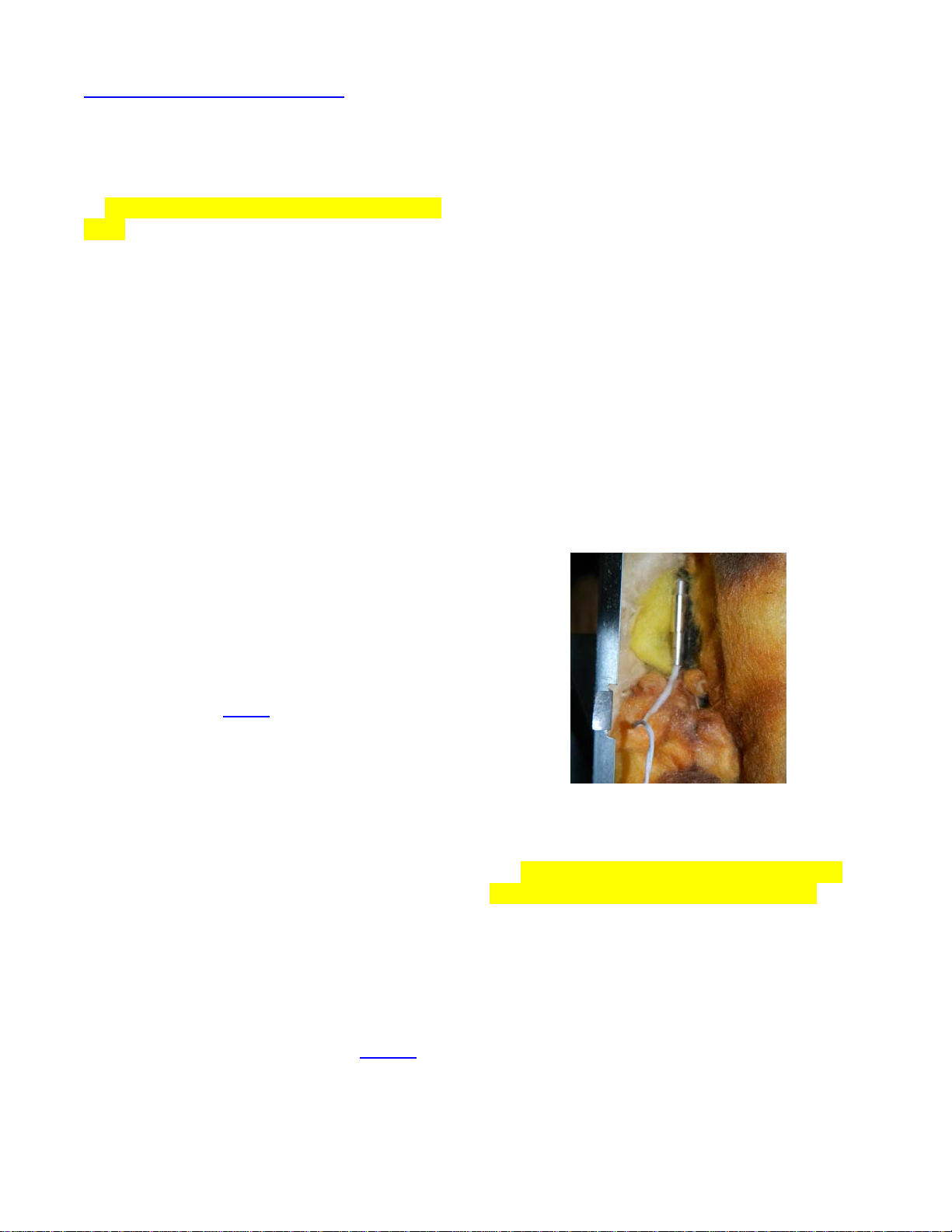
9. Repack the insulation into the boiler. Pack
extra insulation around the sensor and
between the sensor and any heat sources
such as the flue tube and the electric heaters.
Referencing Fig. 2, pack insulation between
the flue and the sensor, and under the sensor
wire. This will help prevent the heat from flue
tube and electric heaters from affecting the
RTD measurement and insure an accurate
measurement of the boiler tube.
Fig. 2 –Insulate around RTD and Between
Wire and Boiler Tube; Be Sure to Insulate
between Flue Tube and Sensor.
10. Sharp objects, such as the sheet metal
boiler housing can cut the sensor wires. The
result is the ARP will detect an open or short
of the sensor and report an error. Where
applicable, to eliminate this issue, wrap
insulation around the sensor wire where it
exits the sheet metal boiler housing and use
wire ties to secure the wiring so that vibration
cannot cause wiring issues.
4.2 Dometic Temperature Sensor
Dometic has two types of boilers as seen in
Fig 3a and 3b, the right-hand boiler and the
left-hand boiler. Please note the different

ARP Control v5x General Installation Guide 20 ©2013 - 2020 ARPC L.L.C. All rights reserved. 9
04/20/20
relative positions between the RTD sensor
and clip for the left or right-hand boilers.
On the Dometic boiler tube, there are usually
several crimps to hold the inner pump tube.
The best location for the temperature sensor
is above these crimps as shown in Fig 3b -
Sensor Location 1. If it is difficult to mount the
temperature sensor above these crimps,
make sure the tip of the temperature sensor
is in good contact with the boiler tube so that
reliable temperatures are measured by the
temperature sensor (Fig 3b Sensor - Location
2).
Please see Dometic Install on our Website
4.3 Norcold Temperature Sensor
Most Norcold boiler tubes are located in front
of the flue tube; exceptions are N31xx and
Polar 7, 8, 10. Thus, the first tube that is seen
when accessing the boiler assembly is
usually the boiler tube. The location of the
flue tube determines the RTD clip alignment
in step 5. Generally the Norcold clip would be
to the right as seen in Fig. 4a.
Fig. 3a
–
Temperature Sensor - Dometic
Right-Hand Boiler
Fig. 3b
–
Temperature Sensor - Dometic
Left-Hand Boiler
Fig. 4a
–
Temperature Sensor Alignment -
Norcold
Fig. 4b
–
Temperature Sensor - Norcold

ARP Control v5x General Installation Guide 20 ©2013 - 2020 ARPC L.L.C. All rights reserved. 10
04/20/20
INSTALLATION - CONTROLLER
5.1 Mounting Location
We recommend mounting the ARP control
within the cooling unit compartment, this is
the preferred location. Referencing the
figures, you will need to locate the following
features of your RV refrigeration system:
•Cooling unit access door (louvered door
that accesses the rear of the refrigerator)
•Refrigerator manufacturers' control unit
•Suitable power supply
Fig. 5
–
ARP Mount on Fridge Control Box
5.2 Interior Location
As of v5.x, we no longer recommend interior
installation of our control. There is no need to
install on the interior of the RV unless one
enjoys gadgets.
If you choose the custom order option at
ARPrv.com we can add extended wires for a
fee. Contact us before purchase; we do not
suggest user extension of the wires due to
reliability issue from bad wire connections.
We will not warranty any issues that result
from self extension of the existing wires
supplied with the control.
Fig. 6
–
Housing Wire Routing & Water
Drain
CAUTION Referencing Fig. 6, the wires
attached to the circuit board may not be
routed nor exit the housing above the dashed
line, and in the zone marked No Route Zone.
The AWG 18 gauge wires do not fit under the
LED display and the circuit components are
vulnerable to damage in this zone. Damage
resulting from carelessness is not covered by
warranty for any control. Also, the control
must be mounted so that the holes at the
bottom of the housing are facing down to
allow water to drain from the control, failure to
mount the control so that there is a drain will
void the warranty. In addition, the wires shall
have a drip loop so water cannot run down
the wire and into the control. The control is
not designed for submersion in water.
5.3 Exterior Mounting
Fig. 5 shows a typical installation where the
ARP is installed on or near the manufactures'
control box. Most of the manufactures
controls have 1/4" of clearance between the
components inside the box and the outside
housing where the ARP is mounted. Please
remove the cover to the manufactures'
control and check the clearances if in doubt
before installing any screws.
WIRING the ARP
6.1 Important Information
DANGER The RV must be
disconnected from shore power (120VAC)
and 12VDC power removed by disconnecting
the batteries before performing any wiring.
CAUTION The sequence of wiring,
connections, and connector type is
extremely important and affects the
warranty. See WIRING OVERVIEW for
wiring sequence and details that affect the
warranty.
Due to variations in refrigerator design to
which you may be adding the ARP, the
description of how to wire your particular
refrigerator may not be listed here. The

ARP Control v5x General Installation Guide 20 ©2013 - 2020 ARPC L.L.C. All rights reserved. 11
04/20/20
following wiring diagrams are minimal, some
components are omitted. If you have any
difficulty, please contact our technical support.
RV manufactures should fuse the power
supply to the fridge with a 5-8 amp fuse. The
owner of the ARP Control needs to confirm
the fridge power supply has proper circuit
protection. For example, referencing Fig. 1b
the yellow wire that supplies power to the
fridge control and the blue wire that supplies
power to fans shall not exceed 8A & 5A
respectively. Most fridge controllers or fans
do not exceed 2A when functioning properly,
thus for most applications where the ARP
Control is not powering 12VDC heaters or
other high amperage loads associated with
the fridge the ARP should perform fine.
Please see Fig. 24 for high amperage
applications. Install inline fuses or circuit
breaker of proper amperage and/or contact
support if in doubt.
Once the ARP is installed the installer must
test the ARP to insure that the ARP and also
the manufactures' control are operating
correctly. All absorption RV refrigerators work
on similar principles. You can connect the
ARP Control to turn off the heat source of
your absorption refrigerator using one of 4
methods:
1) Stop power from reaching the
manufactures’ refrigerator controller.
2) Stop power from reaching the
manufactures’ flame sensor if the
refrigerator has a manual control (see Fig.
23).
3) Stop power from reaching the wire going
to or from the manufacturer’s temperature
monitoring device, such as the boiler
thermo-switch or NHTSA type recall kit.
Note: At the time of this writing, the ARP
adds a higher level of safety than most
NHTSA kits because the ARP measures
boiler temperature and turns off the heat
source at a lower temperature to avoid
damaging the unit. The recalls to date are
retroactive devices, they respond after a
failure of the fridge rather than preventing the
damage that may result in failure of the fridge
and in turn fire issues.
WARNING The ARP does not interfere
with the NHTSA or other kits provided by the
manufactures if and only if the ARP is
installed correctly. The ARP must be
connected so that manufactures' safety
devices continue to perform their normal
operation. Do not disable manufacturer safety
devices and ensure that they operate
properly.
6.2 RV Wire Color-Code Standards
This discussion begins with the fact that there
are no standards for RV wiring color-code.
For example, power and ground color-code
standards for automotive is green for a
ground wire and red for +12VDC. ARP will
stick to this standard for the wiring drawings.
It is up to the installer to determine the actual
color of the power and ground in their RV,
these colors are unique to a particular RV
and change between two identical RVs.
In many of the ARP wiring diagrams a
number in a circle is used to identify
components. The reason is to facilitate verbal
and written communication of a particular
wiring diagram.
6.3 Temperature Sensor Wiring
The RTD temperature sensor is connected to
the ARP via a purple/white twisted wire. The
RTD wires are not polarized; they may be
installed in either position on the sensor.
CAUTION Make sure that no sharp
objects such as the sheet metal boiler
housing can cut the sensor wire. See Fig. 7b
for wire routing to avoid igniter noise.
6.4 Wiring Diagrams Symbols
Fig . 7a is the symbol used in the following
wiring diagrams to indicate a wire that will be
removed from the fridge and replaced by the
ARP Control wiring.
Fig. 7a
–
Wire Removal Symbol

ARP Control v5x General Installation Guide 20 ©2013 - 2020 ARPC L.L.C. All rights reserved. 12
04/20/20
Fig. 7b
–
Boiler Sensor Wire Routing
NORCOLD WIRING GUIDE
7.1 Norcold Early Style Controls
Fig. 8 is a typical early style control board.
Please use Web Resources for details.
7.2 Early Housing Switch Recall
Fig. 9 drawing shows the fridges such as the
N410, N510, N611 and N811 with the boiler
housing thermal switch.
7.3 Late Housing Switch Recall
Fig. 10, the only difference between this
wiring and Fig. 9 is that the ARP is wired
inline with the Norcold controller power
supply rather than the thermal switch.
7.4 Early Style Norcold Recall
Fig. 11 has been included for the special
case of wiring the N611, N811 and 1200
series Norcold fridges that have the NHTSA
recall kit. Note, the recall ground is not shown.
7.5 Late Style Norcold Recall
Fig. 12 only differs from Fig. 11 by the way
that the ARP Control is wired directly inline
with the Norcold control box power supply.
Note, the recall ground is not shown.
7.6 Late Style Norcold 3-Way
Fig. 13 shows the late style Norcold 3-way
fridge wiring. Caution needs to be exercised
to wire the ARP Control so that the 12VDC
electric heaters are not powered through the
ARP Control. If in doubt, be sure to put a 3A
inline fuse on the ARP red wire for testing.
Please see 6.2 RV Wire Color-Code
Standards for wiring diagrams.
7.7 Norcold N7, N8, & N10.
Fig. 14 shows the Polar series refrigerators.
Please use this guide combined with the
following webpage for install: Norcold N7x;
N8x; N10x Webpage
7.8 Norcold N3104 & N3150
Fig. 15 shows the wiring for the N31xx fridge.
Please use this guide combined with the
following webpage for install: Norcold 31xx
Webpage
Click Here for ARPrv.com Web Resources to use with Following Diagrams

ARP Control v5x General Installation Guide 20 ©2013 - 2020 ARPC L.L.C. All rights reserved. 15
04/20/20
Fig. 14
–
Polar Series 3-Way
Fig. 15
–
N3104 & N3150
DOMETIC WIRING GUIDE
Note1: The boiler assemblies in the following
drawings are all right-hand boilers with the
exception of the RM1350. If your fridge has a
left-hand boiler the following wiring diagrams
still apply. Please see Fig. 3a and Fig. 3b for
the respective boiler drawings.
Note2: The brown dashed wire with the
circle-x symbol represents the original wire
found on the 12VDC power supply to the
fridge which is replaced by the ARP wiring.
8.1 Typical Dometic without Recall
Fig. 16 shows the early style controls that did
not have any recall devices.
8.2 Early Housing Switch Recall
Fig. 17 shows the early style boiler housing
thermal switch where the power supply is
wired through the housing thermal switch.
8.3 Late Housing Switch Recall
Fig. 18 is identical to Fig. 17 with the
exception that the factory wiring of the boiler
housing thermal switch is directly to the
Dometic control board. The ARP is wired
inline with the RV power supply to the fridge
control in this case.

ARP Control v5x General Installation Guide 20 ©2013 - 2020 ARPC L.L.C. All rights reserved. 16
04/20/20
8.4 Late Model 3-Way
Fig. 19 shows Dometic 3-Way wiring of the
ARP Control. Please note that the 12VDC
heater draws high amperage, thus Dometic
installs the relay identified as #6 in the
drawing.
The ARP must be wired inline with the fridge
control board power supply in this case. Click
here for early 3-Way Fridge.
8.5 RM1350 Type 3-Termanal
Fig. 20 shows the RM1350 with the three
terminal blocks. Please note that the 3
rd
terminal is labeled D+. This is a special case
for wiring the ARP Control. Note that the ARP
is wired between the RV power supply and
the terminal block (+). ARP boiler sensor
wiring is omitted for clarity.
8.6 RM 84xx & RM 85xx
Fig. 21 & 22 shows the wiring for the RM
84xx and RM 85xx fridge. The figure used
depends on how your fridge was wired from
the factory.
Please use this guide combined with the
following webpage for install: RM 84xx & RM
85xx Webpage
Click Here for ARPrv.com Web Resources to use with Following Diagrams
(–)
(+)
1
2
3
4
5
Electric
Heater
ARP
Sensor
Boiler
Tube
Flue
Tube
+
Dometic Right Hand Boiler
Fig. 16
–
Dometic without Thermal Switch Wiring
(–)
(+)
12
3
4
5
Electric
Heater
Boiler
Housing
Thermal
Switch
ARP
Sensor
Boiler
Tube
Flue
Tube
Dometic Right Hand Boiler
+
Fig. 17
–
Early Dometic with Thermal Switch Wiring

ARP Control v5x General Installation Guide 20 ©2013 - 2020 ARPC L.L.C. All rights reserved. 17
04/20/20
Fig. 18
–
Late Dometic with Thermal Switch Wiring
12
3
4
5
Electric
Heater
Heavy
Gauge
Wire
12VDC
Heater
Relay
~12.5
Amp
ARP
Sensor
Boiler
Tube
Flue
Tube
Dometic Right Hand Boiler
6
+
Splice 12VDC Low Amp
Fridge Control Power
Supply Wire
Fig. 19
–
Late Dometic 3-Way
Fig. 20
–
Dometic RM1350

ARP Control v5x General Installation Guide 20 ©2013 - 2020 ARPC L.L.C. All rights reserved. 18
04/20/20
(–)
(+)
Fig. 21
–
Dometic RM8555 without Thermal Switch
(–)
(+)
Fig. 22
–
Dometic RML8555 with Thermal Switch
MANUAL FRIDGE CONTROL & HIGH AMP INSTALL
9.1 Relay Overview
Fig. 23 shows the recommended Tyco relay
P/N 0-1432793-1. This relay is the only type
of relay to use with the ARP Control up to
v4.x. The v5.x relay just needs to be a
12VDC activation coil type. Terminal 86 is the
+12VDC relay activation and terminal 85 is
the activation ground. These terminals must
have a clamping diode; this is why this type
of relay is required for v4.x and earlier.
WARNING The ARP internal relay is
not warranted against failure due to over
voltage conditions by improper relay
installation.
9.2 Typical Manual Fridge Control
Norcold and Dometic
Fig. 23 shows the aforesaid relay
configuration for the control of the manual
type refrigerator safety thermocouple (TC) in
combination with a TC Interrupter.
9.3 Early 3-Way Norcold and
Dometic & Dometic NDR1402
Fig. 24 can be used when wiring either a high
amperage application (greater than 5A) or if
one desires to mount the ARP remote with
long wires controlling the fridge with a relay.
Other manuals for Fridge Defend
3
Table of contents
Other ARP Automobile Accessories manuals