ARP Control v5.x Troubleshooting Guide 0©2013-2020 ARPC L.L.C. All rights reserved.
104/20/202
SAFETY
1.1 Acronyms and Abbreviations
ARP: ARP Control = Fridge Defend
RTD: ARP Control temperature sensor;
Resistance Temperature Detector is the type
of sensor used.
Q: Flow of fluid either as a gas or liquid.
SPAR: Single Pressure Absorption
Refrigerator.
1.2 Hazard Information
Hazard information includes terms, symbols
and instructions used in this manual or on
the equipment to alert operating and service
personnel to the recommended precautions
in the care, use and handling of the ARP
Control.
1.3 Terms & Warnings Symbols
1.4 Work Safely
There are many ways to install the ARP
Control. Make safety your first priority!
The installer’s knowledge, skill, and ability
are important for safely installing the system
and maintaining or troubleshooting it. If you
are unsure of your ability to use the ARP as
a diagnostic tool, have a qualified individual
do the work.
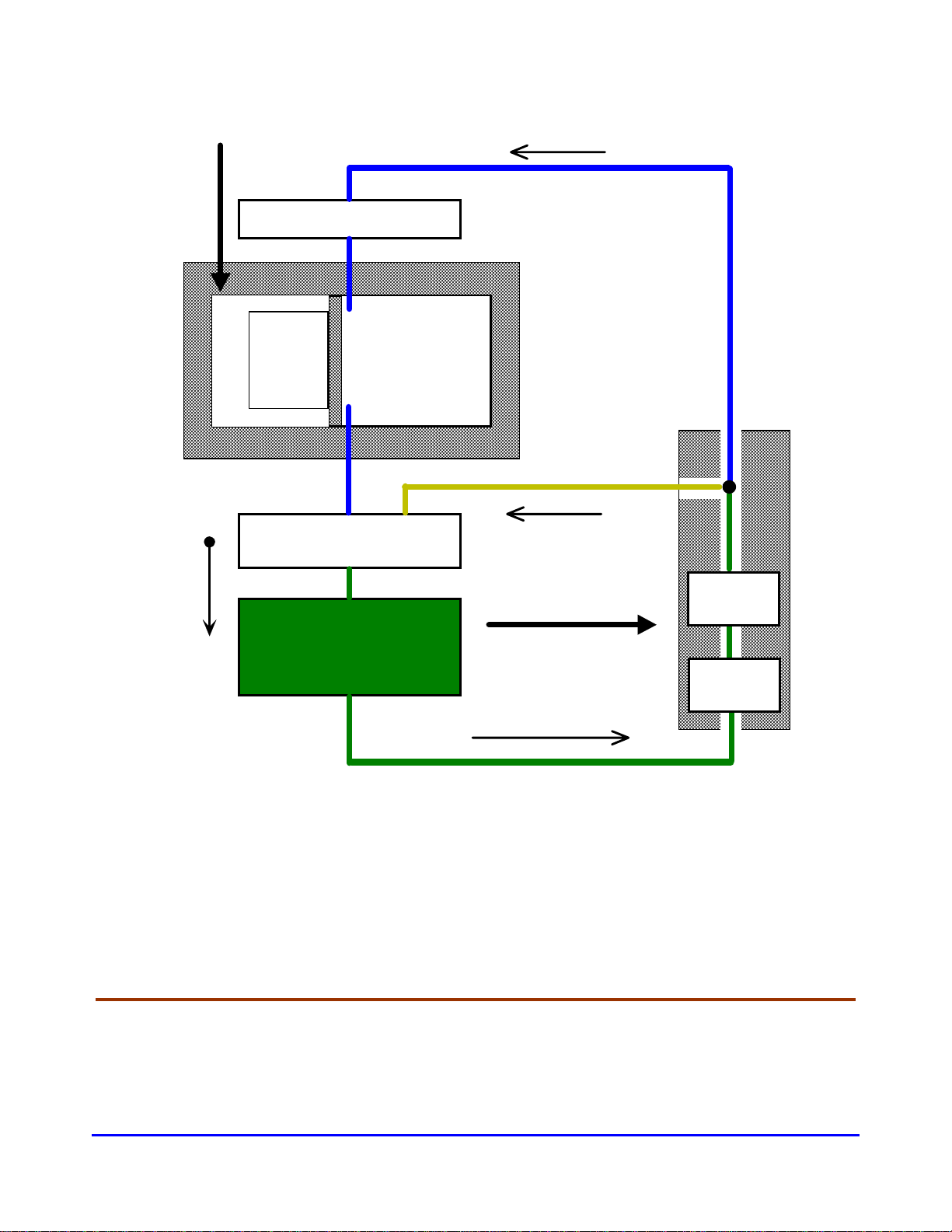
1.5 Operation Safety
The ARP Control and 'ARPrvSafe' infer that
the use and operation of this control can add
a level of safety to your absorption
refrigeration system in your RV. No other RV
absorption refrigerator control monitors the
boiler temperature, and turns off the heat
source to the refrigerator before damage can
be done to the internal fluids in the
refrigerator cooling unit. The ARP cannot
prevent RV refrigerator failure if the
manufacture built the cooling unit in a
manner that would result in premature failure.
In addition, if damage to the cooling unit has
occurred before the ARP was installed; the
ARP cannot remedy this damage
__________________________________________________________________________________________
SETUP MODE
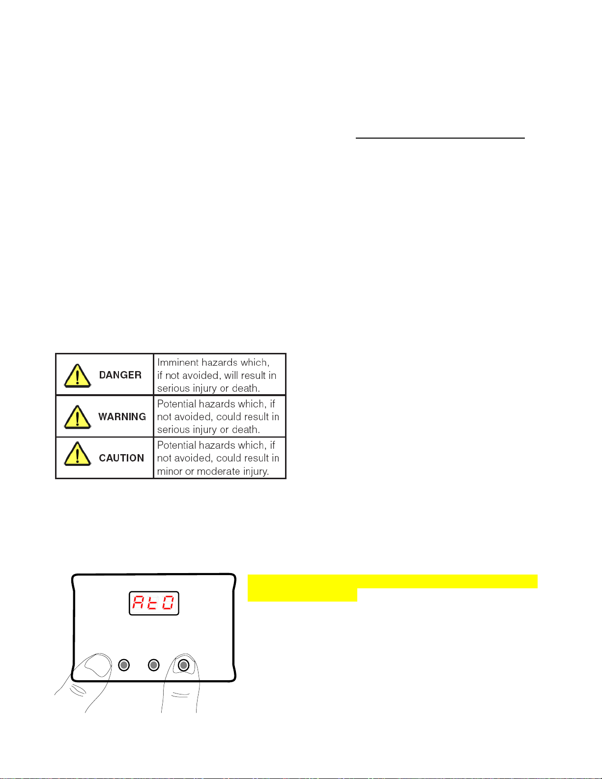
2.1 Activate SetUp Mode
On/Off Display SetUp
To place the control into SetUp mode, begin by turning
off the ARP Control (Please see User Guide →Turn off
ARP Control). When the control is off, the SetUp mode is
activated by holding*the right SetUp button and then
momentarily*pressing the On/Off button. When AtO is
displayed, release the SetUp button.
*Please see User Guide section BUTTON FUNCTION
& Ancillary Graphical User Instructions section Turn
ON Control in SetUp Mode .