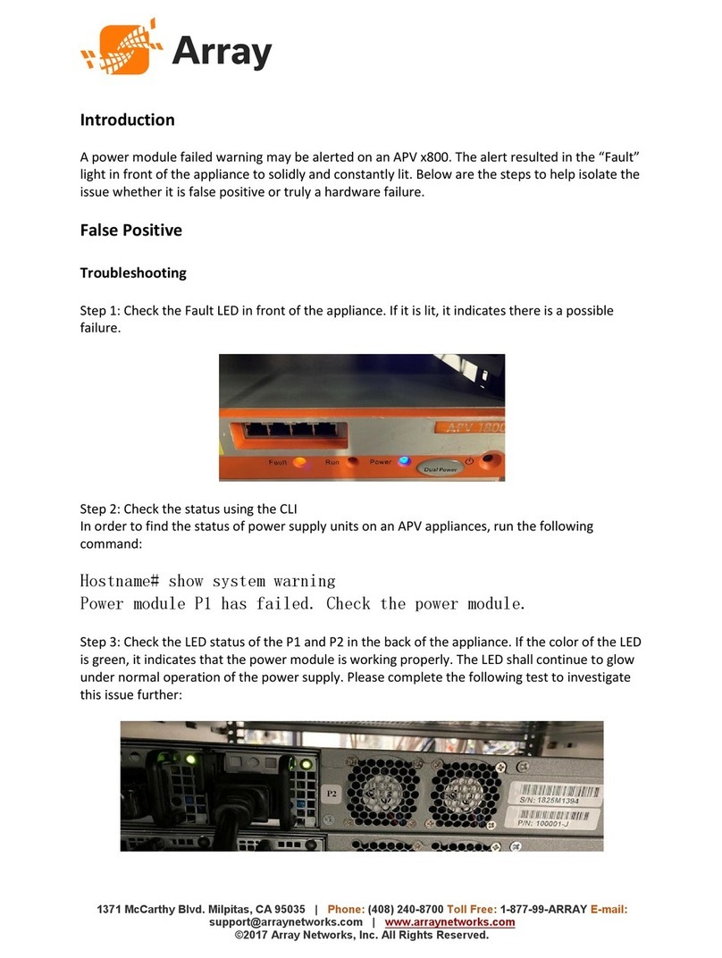
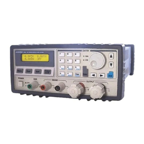
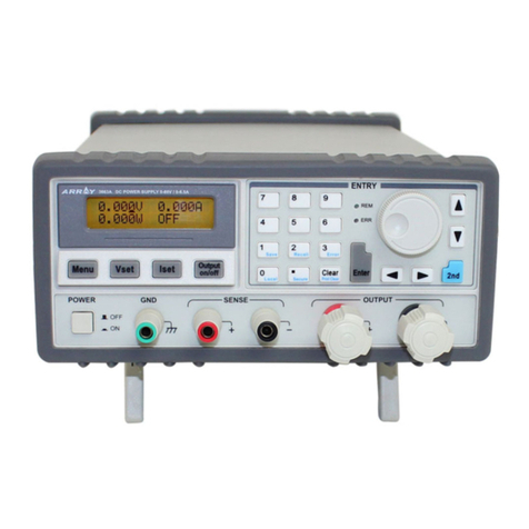
Array electronic 366XA User manual

1
USER’S MANUAL
SWITCHING-MODE DC POWER SUPPLY
ARRAY 366XA
ARRAY ELECTRONIC

2
ARRAY 366XA
SWITCHING-MODE DC POWER SUPPLY
ARRAY 366XA is a series of 500W programmable switching-mode DC power
supplies with RS-232, USB (optional) and GPIB (optional) interfaces. The good
durability, simple operation, low noise, excellent output accuracy as well as the
adjustment from 0V make this series of reliable power supplies the right choice for
many applications. It provides flexible and stable DC power for various design and
test environments.
Versatile Bench-Top Features
*High definition liquid crystal display
*Full-featured keyboard and knobs
*High-efficient switching-mode power supply
*The same continuous adjustment (0-Vout) as the linear power supply
*Low ripple and noise which rivals the linear power supply
*Excellent line and load regulation
*Up to 10 operating states storage and recall
*Portable, ruggedized case and flexible system functions
*Standardized USB interface, optional GPIB and optional USB interface
*SCPI ( Standard Commands for Programmable Instruments) compatibility
*Direct setting of I/O Parameters from front-panel

3
The Front Panel at a Glance
1.ACpowerswitch 2.Senseterminals
3. Earth ground terminal 4. Supply output terminals
5. Output on/off key 6. Left/Right key
7. Control knob 8. Up/Down key
9. Menu setting key 10. Voltage setting key
11. Current setting key 12. Switch key for second function
13. Store key for second function 14. Recall key for second function
15. Error key for second function 16 Local key for second function
17. Secure key for second function 18. Number key
19. Clear key for second function 20. Enter key
21. Display screen 22. ERR annunciator
23. REM annunciator
1. AC power switch: Turns the AC power on and off.
2. Sense terminals: Tests remote voltage, the positive pole is in red, the negative pole
is in black.
3. Earth ground terminal:It is connected to the chassis and earth ground.
4. Supply output terminals: Supply output, the positive output terminal is in red, the
negative output terminal is in black.
5. Output on/off key: Turns the power supply on/off.
6. Left/Right key: Moves the blinking digit to left or right, or selects different options.
7. Control knob: Adjusts the value of the blinking digit or selects different options by
turning clockwise or counter clockwise.
8. Up/Down key: Turns the menu page.
9. Menu setting key: Enters menu setting contents.
10. Voltage setting key (VSET): Displays or modifies the present voltage setting
value.
11. Current setting key (ISET): Displays or modifies the present current setting value.

4
12. Switch key for second function (2nd): Enables the second function of other keys.
13. Store key for second function (Save): Stores the present operating states in
location “0”, “1”, … “9”.
14. Recall key for second function (Recall): Recalls a previously stored operating
state from location “0”, “1”,…“9”.
15. Error key for second function (Error): Checks or reads the error codes.
16. Local key for second function (Local): Returns the power supply to local mode
from remote control mode.
17. Secure key for second function (I/O config): Secures and unsecures the power
supply for calibration.
18. Number key (0-9 and.): Sets values.
19. Clear key for second function (Clear): Clears present input value or exits current
operation.
20. Enter key (Enter): Confirms present setting values or option.
21. Display screen: Shows parameters and status of power supply.
22. ERR annunciator: When some error is detected, ERR annunciator is on.
23. REM annunciator: When the power supply is in remote control mode, REM
annunciator is on.
Front-Panel Display Messages
0.000V Display present voltage value.
0.000A Display present current value.
0.000W Display present power value.
OT The power supply is in over-temperature state.
OV The power supply is in over-voltage state and the supply output is
disabled.
OFF The output of power supply is off.
ERROR Hardware or remote interface control commands errors are detected and
the error bits have not been cleared or read.
Unreg The present output of the power supply is unregulated. (The output is
neither CV nor CC.)
CV The output of power supply is in CV mode.
CC The output of power supply is in CC mode.

5
The Rear Panel at a Glance
1.ACinlet 2.Fuseholder
3. RS-232 interface connector 4. GPIB or USB interface connector (optional)
5. Fan outlet
An Introduction to this Manual
General Information
Apart from a general description of your power supply, it provides instructions for
checking your power supply, selecting power-line voltage and connecting to AC
power.
Initial Operation
It ensures that the power supply develops its rated outputs and responds to operation
from the front panel properly.
Front-Panel Operation
It describes the use of front-panel keys and knobs in detail and how to use them to
operate the power supply from the front panel. And it also shows how to configure the
power supply for the remote interface and introduces the calibration features in brief.
Remote Interface Reference
It contains the reference information to help you program the power supply over the
remote interface, and explains how to program for status reporting as well.
Application Programs
It provides some remote interface applications to help you develop programs for your
application.

6
Tutorial
It describes basic operation of the power supply and gives specific details on the
operation and use of ARRAY 366XA power supplies.
Specifications
It lists the power supply’s basic specifications.

7
Contents
Chapter 1 General Information ……………………………………...................... 11
General Information………………………………………………………………… 11
Safety Considerations………………………………………………….. ………… ...11
Description……………………………………………………………...................... 11
Installation……………………………………………………………………………12
Initial Inspection……………………………………………………….......................12
Mechanical Check……………………………………………………………………12
Electrical Check……………………………………………………………………12
Temperature Control………………………………………………………………… 12
Rack Mounting……………………………………………………………………….13
Chapter 2 Initial Operation ………………………………………………………..14
Initial Operation ……………………………………………………………………..14
Preliminary Checkout………………………………………………………………..14
Power-Line Cord……………………………………………………………………..14
Fuse Replacement……………………………………………………………………15
Power-On Checkout………………………………………………………….15
Self-test started……………………………………………………………….15
Self-test accomplished………………………………………………………..15
Enabling the outputs…………………………………………………………..15
Output Checkout……………………………………………………………….16
Voltage Output Checkout………………………………………………………16
Current Output Checkout………………………………………………………17
Chapter 3 Front Panel Operation……………………………………………20
Front Panel Operation………………………………………………………….20
Front Panel Operation Overview………………………………………………...20
Output on/off…………………………………………………………………….20
Constant Voltage Output Setting…………………………………………………21
Connecting a load to the relevant output terminals………………………………...21
Turning on the power supply……………………………………………………….21
Setting desired output voltage……………………………………………………….21
Setting maximum current……………………………………………………………21
Enabling the outputs…………………………………………………………………22
Verifying that the power supply is in the constant voltage mode………………….22
Constant Current Output Setting…………………………………………………22
Connecting a load to the relevant output terminals………………………………….22
Turning on the power supply………………………………………………………..22
Maximum output voltage setting…………………………………………………..22
Setting the desired output current……………………………………………………23
Enabling the outputs………………………………………………………………….23
Verifying that the power supply is in the constant current mode…………………..23

8
Menu Setting ………………………………………………………………………24
Main Menu Description…………………………………………………………….24
Storing and Recalling………………………………………………………………24
Error Messages Display…………………………………………………………….25
Local/ Remote Operation Switch…………………………………………………..25
Protection Function…………………………………………………………………26
Abnormal Latched State Clearance…………………………………………………26
Over-Voltage…………………………………………………………………………26
Over-Temperature…………………………………………………………………….26
The Power Supply Calibration……………………………………………………….27
Calibration Instrument………………………………………………………………..27
Cautions……………………………………………………………………………..27
Calibration Procedures………………………………………………………………27
Chapter 4 Remote Interface Reference ………………………………………….31
Remote Interface Reference………………………………………………………….31
SCPI Command Summary…………………………………………………………31
An Introduction to the SCPI Language…………………………………………….32
Command Format Used in This Manual……………………………………………33
Command Separators………………………………………………………………..34
Using the MIN and MAX Parameters……………………………………………….34
Querying Parameter Settings…………………………………………………………34
SCPI Command Terminators……………………………………………………….35
SCPI Parameter Types………………………………………………………………35
Numeric Parameters…………………………………………………………………35
Discrete Parameters………………………………………………………………….35
Boolean Parameters………………………………………………………………….35
String Parameters……………………………………………………………………35
Output Setting and Operation Commands…………………………………………..36
Trigger Commands………………………………………………………………….36
System-Related Commands…………………………………………………………36
Calibration Commands………………………………………………………………37
Status Reporting Commands……………………………………………………….37
RS-232 Interface Commands……………………………………………………….38
Simplified Programming Overview…………………………………………………38
Using the APPLy Command……………………………………………………….38
Using the Low-Level Commands………………………………………………….38
Selecting a Trigger Source…………………………………………………………39
Using the APPLY Command………………………………………………………39
Output Setting and Operation Commands………………………………………….40
Measurement Commands…………………………………………………………..40
Output on/off and Tracking Operation Commands………………………………….41
Output Setting Commands………………………………………………………….41
Trigger Source Choice………………………………………………………………43
9
Bus (Software) Triggering…………………………………………………………43
Immediate Triggering……………………………………………………………….44
Trigger Commands……………………………………………………………….44
System-Related Commands………………………………………………………….44
Calibration Commands……………………………………………………………….47
RS-232 Interface Commands………………………………………………………48
The SCPI Status Registers…………………………………………………………48
What is an Event Register?.......................................................................................48
What is an Enable Register?.....................................................................................49
The Questionable Status Register……………………………………………………50
The Standard Event Register…………………………………………………………51
The Status Byte Register……………………………………………………………53
Status Reporting Commands……………………………………………………….53
SCPI Conformance Information……………………………………………………55
SCPI Confirmed Commands…………………………………………………….55
Device-Specific Commands………………………………………………………57
Chapter 5 Application Programs………………………………………………….58
Application Programs………………………………………………………………...58
RS-232 Operation Using QuickBACSIC ………………………………………….58
Chapter 6 Tutorial………………………………………………………………….59
Tutorial……………………………………………………………………………….59
An Overview of ARRAY 366XA Operation…………………………………………59
Output Characteristics………………………………………………………………59
Unregulated State…………………………………………………………………….60
Unwanted Signals…………………………………………………………………….60
Connecting the Load………………………………………………………………..61
Output Isolation………………………………………………………………………61
Multiple Loads……………………………………………………………………..61
Considerations……………………………………………………………………….62
Capacitive Load……………………………………………………………………..62
Inductive Load………………………………………………………………………..62
Pulse Load……………………………………………………………………………62
Reverse Current Load………………………………………………………………62
Extending the output………………………………………………………………..62
Reliability………………………………………………………………………….63
Chapter 7 Specifications ……………………………………………………..64
Specifications………………………………………………………………………..64
Performance Specifications………………………………………………………….64
Transient Response Time……………………………………………………………65
Command Processing Time………………………………………………………….65
Supplemental Characteristics………………………………………………………65

10
APPENDIX Error Messages …………………………………………………68
Error Messages…………………………………………………………………….68
Execution Errors…………………………………………………………………….68
Self-Test Errors……………………………………………………………………….71
Calibration Errors ……………………………………………………………………72

11
Chapter 1 General Information
General Information
This chapter provides a general description of your power supply. And it also contains
instructions relate to initial inspection, selecting the power-line voltage, and
connecting your power supply to AC power.
Safety Considerations
This power supply is a safety instrument with a protective earth terminal. The
terminal must be connected to earth ground through a power source with a 3-wire
ground receptacle when being connected to AC power supply.
Before installation or operation, please check the power supply and read safety
markings and instructions introduced in this manual first. Please see relevant chapters
for related specific information about safety operations.
Description
ARRAY 366XA is a series of programmable switching-mode DC power supply with
stable voltage and constant current. The excellent line and load regulation, extremely
low ripple and noise make it well suited as a high preference power system. 366XA,
as a kind of high-efficient switching-mode supply, features wide supply input voltage
from 100-240AC, high power factor and a minimum output of 0V.
Output voltage or current can be adjusted independently from front panel, or
controlled over RS-232, USB, or GPIB interface. Buttons and knobs on the front
panel can be used to adjust voltage and current of a selected output; calibrate again
without opening the case when the precision falls down (including change password
for calibration); switch the power supply from remote control mode to local mode; set
and monitor the power supply over remote interface; monitor the setting and output of
power supply via the liquid crystal display in front panel, and all the status indication,
error information displayed during working.
When being controlled over remote interface, it can be used both as a listener and a
speaker at the same time. The power supply can be set and data can be returned over
RS-232, USB, or GPIB interface by an external controller. The following functions
can be performed through RS-232, USB, or GPIB interface:
*Voltage and current setting
*Voltage and current readback
*Enable or disable track mode
*Present and stored status readback
*Programming syntax error detection
*Calibration
*Output on/off
*System self-test

12
This power supply is equipped with a liquid crystal display for displaying the output
of voltage and current. A 5-digit voltage and a 5-digit current could show the actual or
setting value of a selected supply simultaneously. And the liquid crystal display can
show the current mode of power supply。
Connections to the power supply’s output and to chassis ground are made to binding
terminals on the front panel. The Sense terminals can remotely sample the power
supply’s voltage. The positive and negative terminals of each output can be grounded,
or kept a certain voltage with the chassis ground. But voltage between each output
and the chassis ground should be kept within ±240 Vdc. The power supply is provided
with a detachable 3-wire grounding type power cord. The AC line fuse is on the rear
panel. It can be extracted for replacement when needed.
The power supply can be calibrated from the front panel directly without opening the
cabinet. Correction factors are stored in non-volatile memory. You can guard against
unauthorized calibration by using the “Standard” calibration protection function.
Installation
Initial Inspection
When you receive your power supply, please check it for any obvious damage that
may have occurred during shipment or resulted from other reasons. If any damage is
found, contact the carrier and the Sales Office immediately in order to deal with it in
time.
Keep the original packing materials in case the power supply has to be returned to
Array for repairing in the future. If you return the power supply for service, please
attach a tag identifying the owner and model number. A brief description of the
malfuction is also needed.
Mechanical Check
This check confirms that there are no broken keys or knob, and that the cabinet and
panel surfaces are free from dents and scratches, and that the display is not scratched
or cracked as well.
Electrical Check
Please see Chapter 2 for an initial operation procedure. When successfully completed,
it can be convinced that the power supply is operating in accordance with its
specifications.
Temperature Control
The power supply’s performance will not be affected when operating within the
temperature range of 0°C to 40°C, and within the temperature range of 40°C to 55°C,

13
the over-temperature protection may take effect, depending on the input voltage and
output power. A brushless fan is used to cool the power supply by drawing cool air
through the two sides and exhausting the heat through the fan outlet on the rear panel.
Sufficient space must be left at the rear and two sides of the cabinet for air circulation
when the power supply is installed. Please remove the rubber bumpers for rack
mounting.
Rack Mounting
The power supply could be installed in a standard 19-inch rack.
Please remove the rubber bumpers at the front and end of power supply before
installing.

14
Chapter 2 Initial Operation
Initial Operation
This chapter mainly focuses on three basic tests which should be performed before the
operation of the power supply: the preliminary checkout, the power-on checkout, and
the output checkout. The preliminary checkout is to check if the power supply could
run correctly. The power-on test includes a self-test that checks the internal
microprocessors and checks if the user are allowed to examine the display at the front
panel under the condition of applying power to the supply properly. The output check
ensures that the power supply develops its rated outputs and properly responds to
operation from the front panel.
In order to make sure the power supply is in accordance with
what is required and have a better command of power supply
features for later use, it is suggested that both the experienced
and the inexperienced users should read this chapter prior to
operation
Preliminary Checkout
ARRAY 366XA power supply can be used from a rated 100 V to 240 V single phase
AC power source at 47 to 63 Hz. There is an indication below the AC power inlet on
the rear panel showing the rated input voltage set for the power supply at the factory.
Power-Line Cord
The power supply is shipped from the factory with a power-line cord that has a plug
appropriate for your location. Please contact the nearest ARRAY Sales and Service
Office if the wrong power-line cord is included with your power supply. Your power
supply is equipped with a 3-wire grounding type power cord with a diameter of
1mm2X3 and the third conductor is the ground lead. The power supply can operate
properly only when the power-line cord is plugged into an appropriate receptacle. Do
not operate your power supply without adequate cabinet ground connection.

15
Fuse Replacement
1 Replace the fuse
Step 1: Remove the fuse-holder belowAC power inlet.
Step 2: Replace the fuse with the correct one that meets the requirements.
Step 3: Put back the fuse holder.
For 115VAC operation, 10AT fuse must be used;
For 230VAC operation, 6AT fuse must be used.

16
Power-On Checkout
The power-on test includes an automatic self-test that checks the internal
microprocessors and a system self-test after the power supply is turned on, and
examines the information relate to self-test process shown on the front panel. You will
observe the following sequence on the display:
1. Self-test started
It begins with an initial operation immediately after pressing the power
switch on. Then self-test starts, involving the test of internal
microprocessor and whole power supply system.
2. Self-test accomplished
If there is no error or abnormity has been detected during self testing, the supply will
enter into power-on/reset state and the output will be disabled.
In this figure, “OFF” indicates that supply output is forbidden.
3. Enabling the outputs
Press “Output on/off” to enable the outputs. The “OFF” annunciator on the
lower right corner of the display turns off, while the “ON” and “CV”
annunciators at the same place turn on. And the display switches to
monitor mode automatically to monitor the actual value of output voltage
and current.
If power-on self-test has detected any error or abnormity, the
“ERROR”annunciator is lit. For specific information about errors, please
see related chapters in appendix.

17
Output Checkout
The output checkout is to ensure that the power supply develops its rated outputs and
properly responds to various operations. Specific steps are shown as followings:
Voltage Output Checkout
1. Turn on the power supply.
Press the “Power-on” button, and finish the power-on checkout. Usually
the power supply will go into the power-on / reset state automatically.
“OFF” will be shown in the lower right corner of the display and both the
output voltage and current are 0.
2. Enable the outputs.
Press the “OUT on/off” button to turn on the power supply outputs. Now
the display is in monitor mode; the “CV” or “ON” annunciator in the
lower right corner of the display is lit. At the same time a 5-digit voltage
meter and a 5-digit current meter are displayed, respectively showing the
actual value of output voltage and current of the power supply.
3. Check if the voltmeter properly responds to knob control on front
panel for the supply.
Knob Checkout
When the power supply output is on and the display is in monitor mode,
move the blinking digit to voltage value displayed by pressing the key
“Left”. Turn the knob clockwise or counter clockwise to check that the
voltmeter responds to knob control to increase or decrease and the
ammeter indicates nearly zero.
Key Checkout
When the power supply output is on and the display is in monitor mode,
press key “VSET”, the voltage setting value in the LCD will blink. Press
the number keys on front panel directly to set voltage value needed.
Then press “Enter” to verify and finish setting and go back to monitor
mode. This process is to check that the voltage value displayed responds
to the key operation correctly.
4 Check if the voltage can be adjusted from zero to the maximum rated
value.
Adjust the knob until the voltmeter indicates 0V and then adjust the knob
gradually until the voltmeter indicates the maximum rated value with the
method explained in last step. At the same time check if the voltmeter
and output voltage changes as voltage changes.

18
Current Output Checkout
1. Turn on the power supply.
Press “Power-on” button and finish the power-on checkout. Usually the
power supply will go into the power-on / reset state automatically and
the “OFF” annunciator in the lower right corner of the LCD turns on.
Both the voltage value and current value are 0.
2. Connect a short across (+) and (-) output terminals of the supply with
an insulated test lead. The sectional area of the shorting stub should be
larger than 1.5mm2.
3. Enable the outputs.
Set the supply voltage to 5V according to the voltage setting measure.
Press the “OUT on/off” button, the display is in monitor mode. At the
same time a 5-digit voltage meter and a 5-digit current meter are
displayed, showing the actual value of output voltage and output current
of the power supply respectively. The CV or CC modes depend on the
resistance of the test lead.
4. Adjust the voltage limit value to 1.0 V.
Adjust the voltage limit to 1.0 V to assure CC operation. Please see
related chapters about voltage and current setting from front panel in this
manual for specific operations.
5. Check that the front-panel ammeter properly responds to the key and
knob operations form the front panel.
Knob Checkout
When the output of the power supply is turned on and the display is in
monitor mode, press “Right” key to move the blinking digit to current
value displayed, and turn the knob clockwise or counter clockwise to
check if the current value displayed increases or decreases as current
changes.
Key Checkout
When the output of the power supply is turned on and the display is in
monitor state, press “ISET” and the current setting value is blinking.
Press the number keys on front panel directly to set current value needed.
Then press “ENTER” to verify and finish setting and go back to monitor
mode. This process is to check that the current value displayed responds
to the key operation correctly.

19
6. Ensure that the current can be adjusted from 0A to the maximum rated
value.
Adjust the knob until the ammeter indicates 0A and then until the
ammeter indicates the maximum rated value.
If an error has been detected during the output checkout procedures, the
ERROR annunciator will turn on. Refer to the related chapters in
appendix for more specific error information.

20
Chapter 3 Front Panel Operation
Front Panel Operation
`
3.1 Front Panel Operation Overview
• Output on/off
• Constant Voltage setting
• Constant Current setting
• Menu Setting
• Storing and Recalling
• Error Messages Display
• Local/Remote Operation switch
• Protection Function
•Power Supply Calibration
3.2 Output on/off
The output of the power supply could be switched on or off through this
button.
When the output of the power supply is disabled, you can enable it by
pressing “Out on/off” key, and it can be turned off by pressing this key
again.
When the output of the power supply is enabled, “CV”, “CC” or “Unreg”
will be displayed in the lower right corner of the display. “CV” indicates
that the supply source is in constant voltage state, “CC” indicates that the
power supply is in constant current state and “Unreg” indicates that the
power supply is operating in unstable state (Neither in constant voltage
nor constant current status).
For example: if the power supply output is in constant voltage state, the
actual output voltage is 5V and the actual output current is 3A, the display
will show as follows:
When the output of the power supply is off, the “OFF” annuciator in the lower left
corner of the display is lit and the keys as well as the knobs are still valid. Then the
display will show as follows:
Table of contents
Other Array electronic Power Supply manuals

Array electronic
Array electronic 3720A User manual

Array electronic
Array electronic 366X User manual

Array electronic
Array electronic 3645A User manual

Array electronic
Array electronic 3751A User manual

Array electronic
Array electronic 367 Series User manual

Array electronic
Array electronic APV 800 Series User manual

Array electronic
Array electronic 3645A-TYPE User manual

Array electronic
Array electronic 3645A User manual

Array electronic
Array electronic 3646A User manual