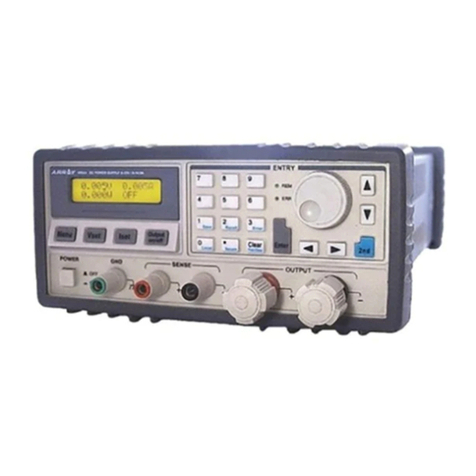
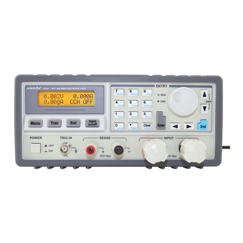
Array electronic 3751A User manual

Contents
USER’S MANUAL
375X SERIES ELECTRONIC LOAD

Contents
Contents
Safety Instruction …………………………………...…….....................................................1
Chapter I General Introduction ……………………………………………………...……..3
1.1 Function Features …………………………………………………………..……………3
1.2 Front Panel …………………………………………………………………….....……...4
1.3 Rear Panel ……………………………………………………………….……………....5
1.4 Keypad Function ………………………………………………………………..……….5
1.5 Annunciators ……………………………………………………………………..……...7
1.6 Display ………………………………………………………………….……………….8
1.6.1 Main Menu List ………………………………………………………………………8
1.6.2 Port Conguration Menu ………………….…………………………………………9
1.6.3 Transient Operation Menu ……………………………………………….…………10
1.6.4 List Operation Menu ………………………………………………….…………….11
1.6.5 Basic Mode Menu & LCD Information ……………………………………………..13
1.6.5.1 CC Mode Menu ………………………………………………………………….13
1.6.5.2 CR Mode Menu ……………………………………………………………….....14
1.6.5.3 CV Mode Menu ………………………………………………………………….15
1.6.5.4 CP Mode Menu …………………………………………………………………..16
1.6.5.5 +CV Mode Menu ………………………………………..………………………18
1.6.6 Error & Alarm Menu ………………………………………………………………..19
1.6.7 Save Menu ……………………………………………………………………….….19
1.6.7.1 Application Save Menu ………………………………………………………….19
1.6.7.2 Recall Save Menu ………………………………………………………………..20
1.7 Remote Programming ……………………………………………………………….....20
Chapter II Functions and Features ……………………………………………………….21
2.1 Local & Remote Control ……………………………………………………………….21
2.2 Main Functions …………………………………………………………………………21
2.3 Basic Test Functions ……………………………………………………………………22
2.3.1 CC Test …………………………………………………….………………………..22
2.3.1.1 Current Setting Range ……………………………………………….…………..23
2.3.1.2 Immediate Current Level …………………………………………………….….23
2.3.1.3 Triggered Current Level …………………………………………..……………..23
2.3.1.4 Transient Current Vevel …………………………………………..……………...24
2.3.1.5 Software Current Level ……………………………….…………………………24
2.3.2 CV Test …………………………………..………………………………………….24
2.3.2.1 Voltage Setting Range …………………………………………………………...25
2.3.2.2 Immediate Voltage Level ………………………………………..……………….25
2.3.2.3 Triggered Voltage Level …………………………………………..……………..26
2.3.2.4 Transient Voltage Level ……………………………………………….……..…..26
2.3.3 CR Test …………………………………..…………………….……………………26
2.3.3.1 Resistance Setting Range ………………………………………………………...27
2.3.3.2 Immediate Resistance Level …………………………………….…..…………...27
2.3.3.3 Triggered Resistance Level …………………………………….………………..27
Contents
2.3.3.4 Transient Resistance Level …………………………………..……..…………..28
2.3.4 CP Test …………………………………………...………………………………..28
2.3.4.1 Power Setting Range …………………………...………………………………29
2.3.4.2 Immediate Power Level ………………………………………………………...29
2.3.4.3 Triggered Power Level ……………………………………………...………….29
2.3.5 CC+CP Test ………………………………………………………………………..30
2.3.6 CR+CV Test …………………………………………………………………....….30
2.3.7 CP+CV Test ………………………………………………….…………………….31
2.4 Transient Operation ……………………………………………………………...……31
2.4.1 Continuous Transient Operation ……..…………………………………………….32
2.4.2 Pulsed Transient Operation ……………………………………………..…………34
2.4.3 Toggled Transient Operation ……...……………………………………………….36
2.5 List Operation …………………………………………………………………………38
2.6 Triggered Operation …………………………………………………………………..39
2.7 Input Control ………………………………………………………………………….40
2.7.1 ON/OFF of Eload Input ……………………………………………………………40
2.7.2 Von Point/Von Latch ………………………………………………………………40
2.7.3 Current Limit Function in CV Mode ……………………………………………....41
2.7.4 Current Rising Rate ……………………………………………………………......42
2.7.5 Current Falling Rate …………………………………………………………...…..42
2.8 Measurement Function ………………………………………………………….…….43
2.9 Saving and Recalling …………………………………………………………….……43
2.10 Reading Remote Program Errors ………………………………………………..…..45
2.11 Status Report …………………………………………………………….…………..45
2.12 Protection and Alarm Function …………………………………………………..….45
2.12.1 Clearing Latched Protection ……………………………………………………...46
2.12.2 Overvoltage ……………………………………………………………………....46
2.12.3 Overcurrent ……………………………………………………………………….46
2.12.4 Overpower ………………………………………………………………………..47
2.12.5 Overtemperature ………………………………………………………………….47
2.12.6 Reverse Polarity ……………………………………………………………….....48
Chapter III Installation …………………………………………………………………..49
3.1 Initial Check …………………………………………………………………………..49
3.2 Environment/Installation Location …………………………………………………....49
3.3 PowerOn/Self-check …………………………………………………………………..51
3.4 Connection of the Rear Panel ………………………………………………………....52
3.5 Connection of the Front Panel ………………………………………………………...54
3.6 Wiring ………………………………………………………………………...……….55
Chapter IV Local Operation ……………………………………………………………..60
4.1 Local Control …………………………………………………………………...…….60
4.2 Main Operation of the Front Panel …………………………………………………....60
4.3 Connecting to the Power Supply ……………………………………………………...61

Contents
4.4 ON/OFF of Eload Input ……………………………….……………………......……...61
4.5 Basic Operation ……………………….………………………………………….....…61
4.5.1 CC Mode ……………………………………………………………………………62
4.5.2 CV Mode ……………………………………………………………………………64
4.5.3 CR Mode ……………………………………………………………………………66
4.5.4 CP Mode ……………………………………………………………………………68
4.6 +CV Mode ……………..………………………………………………………………70
4.6.1 CC+CV Mode ………………..……………………………………………………..70
4.6.2 CR+CV Mode …………………..…………………………………………………..71
4.6.3 CP+CV Mode ………………..……………………………………………………..72
4.7 Transient Operation ……………………………………………………………………73
4.7.1 Continuous Transient Operation ……………………………………………………73
4.7.2 Pulsed Transient Operation …………………………………………………………75
4.7.3 Toggled Transient Operation ………………………………………………………..77
4.8 List Operation ………………………………………………………………………….79
4.8.1 List Editing …………………………………………………………………….…...80
4.8.2 Starting/Stopping the List …………………………………………………………..83
4.9 Saving and Recalling …………………………………………………………………..84
4.10 Checking and Clearing Protection Setting ……………………………………………86
4.11 Trigger Operation …………………………………………………………………….87
4.12 Main Menu ………………………………………………………………….………..87
4.12.1 Buzzer ……………………………………………………………...……………..88
4.12.2 Encoder ……………………………………………………………………………88
4.12.3 Trigger ……………………………………………………………...……………..89
4.12.4 Calibration …………………………………………………….…………………..89
4.12.5 Information ………………………………………………………………………..89
4.12.6 Safety Code ……………………………………………………………………….90
4.12.7 Date ……………………………………………………………………………….91
4.12.8 Time ……………………………………………………………………………….92
4.12.9 Language ………………………………………………………………………….92
4.12.10 System Default …………………………………………………………………..93
Chapter V Remote Programming Operation …………………………………………….94
5.1 Communication Interface …………………………………………………..………….94
5.1.1 RS232 ………………………………………………...…………………………….94
5.1.2 USB …………………………………………………...……………………………94
5.1.3 GPIB ………………………………………………………………………………..95
5.2 Remote Programming Display …………………………………………………………98
5.3 Sending Remote Setting Commandsb …………………………………………………98
5.4 Returning Data ………………………………………………………………...……….98
5.5 Remote Programming Commands ……………………………………………………..98
5.5.1 Basic Test Mode ……………………………………………………………………99
5.5.2 Transient Level……..……………………………………………………………….99

Contents
5.5.3 Programmable Current Protection …………………………...…………….………..99
5.6 CC Mode Example …………………………………………………………….………..99
5.7 CV Mode Example ………………………………………………………..…………...100
5.8 CR Mode Example ……………………………………………………………..……...100
5.9 Continuous Transient Operation Example ……………………………………….……100
5.10 Pulsed Transient Operation Example …………………………………………….…..101
Specications ………………………………………………………………………………102
Frame Diagram ………………………………………………………………...………….110
Declarations … …………………………………………………………….....……………113

Chapter I General Introduction
ARRAY
1
Safety Instruction
This chapter contains the important safety instructions that the users must follow during operation
and storage. Please read the contents carefully before operation to ensure the safe and optimal use.
Safety Guides:
1. Do not place heavy objects on the instrument. Notes: Only two units can be placed
vertically.
2. To avoid serious impact or improper placement and damage to the instrument.
3. To avoid the electrostatic discharge to the instrument.
4. Please use the matched cable. Please do not use the naked cable.
5. Please do not block or obstruct the ventilation of the fan.
6. Please do not disassemble the instrument unless you are qualified as service personnel.
7. The instrument is not for the measurements performed for CAT I, II and IV.
●(Measure Categories)EN6100-1:2010 specifies the measurement categories and their
requirements as follows. The 375XA falls under category II.
●Measurement category IV is measurement performed at the source of low-voltage installation.
●Measurement category III is for measurement performed in the building installation.
●Measurement category II is for measurement performed on the circuit directly connected to
the low voltage installation.
●Measurement category I is for measurement performed on circuits not directly connected to
the main.
8. Power Supply
●AC Input Voltage: 100~120VAC/200~240VAC (90~132VAC/180~250VAC)
●Frequency: 47~63Hz
●Power: 3751A 80VA Max
●Connect the protective grounding conductor of the AC power cord to an earth ground, to
avoid electrical shock.
9. Cleaning
Disconnect the power before cleaning. Use a soft cloth dampened in a solution of mild
detergent and water. Do not spray any liquid. Do not use chemicals or cleaners containing harsh

Chapter I General Introduction
ARRAY
2
material such as benzene, toluene, xylene and acetone.
10. Operation Environment
●Location: Indoor, no direct sunlight, dust free, almost non-conductive pollution
●Temperature: 0℃~40℃
●Humidity: 0~90% RH
●(Pollution Degrees) EN6100-1:2010 specifies the pollution degree and their requirements as
follows.
●The 375XA falls under degree II.
●Pollution refers to “addition of foreign matter, solid, liquid or gaseous (ionized gases), that
may produce a reduction of dielectric strength or surface resistivity”.
●Pollution degree I: No pollution or only dry, non-conductive pollution accurs. The pollution
has no influence.
●Pollution degree II: Normally only non-conductive pollution occurs. Occasionally, however, a
temporary conductivity caused by condensation must be expected.
●Pollution degree III: Conductive pollution occurs, or dry, non-conductive pollution occurs
which becomes conductive due to condensation which is expected. In such conditions, equipment
is normally protected against exposure to direct sunlight, precipitation, and full wind pressure, but
neither temperature nor humidity is controlled.
11. Storage Environment
●Location: Indoor
●Temperature: -20℃~70℃
●Humidity: <90% RH
12. Disposal
Do not dispose this instrument as unsorted municipal waiste. Please use a separate collection
facility or contact the supplier from which this instrument was purchased. Please make sure
discarded electrical waste is properly recycled to reduce environment impact.

Chapter I General Introduction
ARRAY
3
Chapter I General Introduction
General Introduction of 375XA Eload
ARRAY 375XA electronic load is a new-generation high-performance programmable electronic
load researched by ARRAY ELECTRONIC CO., LTD, which provides powerful test function and
friendly human-machine interface. The electronic load is equipped with RS232, USB and GPIB
interface and supports SCPI standard commands for programmable instrumentation and LabView
development platform, which is widely used in the scientific research and production field of
aerospace, shipbuilding, auto electronics, solar cell and fuel cell.
The “electronic load”, “Eload” or “load” in the manual indicates ARRAY 375XA electronic
load without following instructions.
1.1 Function Features
The main functions and features of ARRAY 375XA Eload are as below:
Four basic testing modes: CC, CV, CR and CP; twelve basic working modes: CCL, CCH,
CVL, CVH, CRL, CRH, CP, CCL+CV, CCH+CV,CRL+CV, CRH+CV, CP+CV;
The 16 bit D/A converters and 24 bit A/D converters incorporated, provide the equipment
with greatly enhanced setting and measurement resolution. The D/A conversion rate can
reach 500 KHz and the high-speed performance is overall increased;
Minimum operating voltage is less than 1.8V at the load’s full rated current. The
maximum current can be achieved even though the input voltage is 0V, which is
especially suitable for the fuel cell, solar cell, auto charger and other new energy test
application. The load is with powerful protection function and is reliable in the most
complicated test environment;
High resolution TFT-LCD display;
High-speed transient test function: the maximum test frequency can reach 50 kHz and the
current response speed can be 15A/us.
Powerful sequential test function: the minimum step time is 10us and the maximum step
time is 99999s. Cyclic times can be set freely and can be chained to another sequence to
realize more complex test procedure;

Chapter I General Introduction
ARRAY
4
The high-efficiency intelligent cooling system can ensure the equipment has a long-term,
full-power, trouble-free and continuous work;
Automatic ON/OFF function effectively simply the test operation;
The combined use of knob and number keypad makes the operation more convenient;
Save/Recall function can save multiple groups of common settings;
With OCP, OPP, OTP protection function and OV, RV alarm function;
Supporting SCPI and LabView and providing necessary PC software.
1.2 Front Panel
1 Air Inlet Air inlet of the cooling air dust
2 LCD display To display the state, test value and setting parameter of the instrument
3 Operation mode key To switch the operation mode of the instrument
4 Power Power ON/OFF
5 Handle To handle the instrument
6 Number pad & function keys To enter the numbers and the functions
7 Direction keys & enter key To move the cursor and to confirm
8 Knob To increase /decrease values
9 Current monitor terminal To isolate the output after the test of the present current
10 External trigger input terminal To input the external trigger signal

Chapter I General Introduction
ARRAY
5
1.3 Rear Panel
The connecting terminals on the rear panel of 375XA series Eload include: the input terminals
(INPUT+ and INPUT-) and voltage test terminals (SENSE+SENSE-), as shown in follows
1. RS232 interface
2. GPIB interface (optional)
3. USB interface
4. Input terminal
5. Voltage test terminal
6. Power input socket & fuse
7. Air outlet
8. Ground terminal: to connect the earth during rack system installation
1.4 Keypad Function
There are four types of keys: function keys, number keys, alternative function keys and direction
keys on the keypad. On the alternative function compound key, the black fond is the first function
and the blue fond is the alternative function. For example, CV is the first function of
key and +CV is the alternative function. If the alternative function is needed to be used, press
key first and then press the corresponding compound key.

Chapter I General Introduction
ARRAY
6
Table 1-1 Key Explanation:
Number 0
Number 1
Number 2
Number 3
Number 4
Number 5
Number 6
Number 7
Number 8
Number 9
Dot
Clear
Epitope shift key
Save key
Recall key
Input ON/OFF key
Confirmation key

Chapter I General Introduction
ARRAY
7
1.5 Annunciators
Table 1-3, Annunciator Explanations:
Green light be on when the input being on
Yellow light be on when the input being standby
Left key
Right key
Upper key
Down key
Delete key
Local key
Error code display key
I/O port configuration key
CC mode selection key
CV mode selection key
CR mode selection key
CP mode selection key
Alternative function shift key

Chapter I General Introduction
ARRAY
8
1.6 Display
1. Date and Time To display the current date and time
2. System State To display the current system state
3. Test Value To display the current voltage, current and power value
4. Operation State To display the current operation mode and the input state
5. Current setting Value To display the current setting value
6. Soft Key To indicate the function of the key below the screen
Description of the Main Menu
1.6.1 Main Menu List
Press dynamic key to enter the main menu as shown in the following diagram:

Chapter I General Introduction
ARRAY
9
The contents of the main menu are as the follows:
Beeper To control the buzzer work or not;
Encoder To control the encoder work or not;
Trigger To control the trigger work or not;
Calibration To calibrate the accuracy of the Eload
, for details please see
Calibration Methods;
Information To display the factory setting;
Security Code
To set the security code for the instrument to avoid the error operation of
the Calibration menu;
Date To adjust the current date of the system;
Time To adjust the current time of the system;
Language To swift the current language of the system;
Default Factory
Value
The current system can be returned to the default factory value.
1.6.2 Port Configuration Menu
Press key to enter the I/O configuration menu as follows:

Chapter I General Introduction
ARRAY
10
Port Configuration Com Port USB GPIB
RS232 Interface
Baud Rate 2400 9600 19200 38400 57600 115200
Parity Bit Non Parity/ Even Parity/ Odd Parity
Data Bit 8 Bit 9 Bit
Stop Bit 1 Bit 2 Bit
USB Interface USB
GPIB Interface GPIB Address Address Value
1.6.3 Transient Operation Menu
In basic mode, press dynamic key to enter the corresponding transient operation
menu. The transient operation menu is as follows:

Chapter I General Introduction
ARRAY
11
Function Explanation Parameter Example
L Level Transient Low Level 1.000A
H Level Transient High Level 6.000A
LowTime Time for transient low level 0.6s
HighTime Time for transient high level 0.6s
RiseTime Time for transient rising edge 0.01s
FallTime Time for transient falling edge 0.01s
Mode Continuous(Cont)Pulse(Puls)Toggle(Togg)Cont
Notes: Transient operation may be used in CC, CV, CR and CP modes.
1.6.4 List Operation Menu
In basic mode, press dynamic key to enter the corresponding list operation menu.
The list operation menu is as follows:

Chapter I General Introduction
ARRAY
12
Number List Steps(0-19)
Name List Name(5 characters)
Total Steps Total steps of list operation
Execution Times Loop Times(1-999)
Link Link(0-19,off)
key Press this dynamic key to return to the main menu;
key Press this key to switch between CCL and CCH;
key Press this key to enter the transient operation;
key Press this key to enter list data edit mode.
In the list operation menu, Select the function by , or key, and select the
data edition or data modification function by knob, or . Then press dynamic
key to enter the list data edition menu as follows:

Chapter I General Introduction
ARRAY
13
1.6.5 Basic Mode Menu & LCD Information
1.6.5.1 CC Mode Menu
Description: In Constant Current Mode, the load units will sink the amount of current
programmed. Regardless of the voltage, the current will stay the same. For more details on CC
Mode, please refer to Page 52.
Voltage Value To display the current input terminal voltage;
Power Value To display the current power value;
Current Value To display the current value
Mode CCH indicates constant current high range;
CCL indicates constant current low range;

Chapter I General Introduction
ARRAY
14
Input State ON/OFF;
Run Time To display the time the load being ON, reset when shutdown or switch mode;
Para Set To set the constant current value, unit: A;
Volt Start To set the start voltage of the load, 0 indicates the function being not enabled;
Current Limit To limit the maximum Current level at the mode
Rising Rate To control the current rising rate when starting
Falling Rate To control the current falling rate when starting
key Press this dynamic key to return to the main menu;
key Press this key to switch between CCL and CCH;
key Press this key to enter the transient operation;
key Press this key to enter list data edit mode.
1.6.5.2 CR Mode Menu
Description: In Constant Resistance Mode, the load units will maintain a constant resistive load by
varying the current. For more details on CR Mode, please refer to Page 57.
Voltage Value To display the current input terminal voltage;
Power Value To display the current power value;
Current Value To display the current value

Chapter I General Introduction
ARRAY
15
Mode CRH indicates constant resistance high range;
CRL indicates constant resistance low range;
Input State ON/OFF;
Run Time To display the time the load being ON, reset when shutdown or switch
mode;
Para Set To set the constant resistance value, unit:KΩ;
Volt Start
To set the start voltage of the load, 0 indicates the function being not
enabled;
Res Limit To limit the minimum resistance level at the mode
RiseRate To control the current rising rate when starting
FallRate To control the current falling rate when starting
key Press this dynamic key to return to the main menu;
key Press this key to switch between CRL and CRH;
key Press this key to enter the transient operation;
key Press this key to enter list operation.
1.6.5.3 CV Mode Menu
Description:In Constant Voltage Mode, the load units will maintain a constant voltage value by
varying the current. For more details on CV Mode, please refer to Page 54.
This manual suits for next models
6
Table of contents
Other Array electronic Power Supply manuals

Array electronic
Array electronic 366X User manual

Array electronic
Array electronic 3645A-TYPE User manual

Array electronic
Array electronic 3645A User manual

Array electronic
Array electronic 367 Series User manual

Array electronic
Array electronic 3720A User manual

Array electronic
Array electronic 366XA User manual

Array electronic
Array electronic APV 800 Series User manual

Array electronic
Array electronic 3645A User manual

Array electronic
Array electronic 3646A User manual