Page 8
FiberLink 3500 Series
FiberLink 3500 Bi-Directional Series User’s Manual
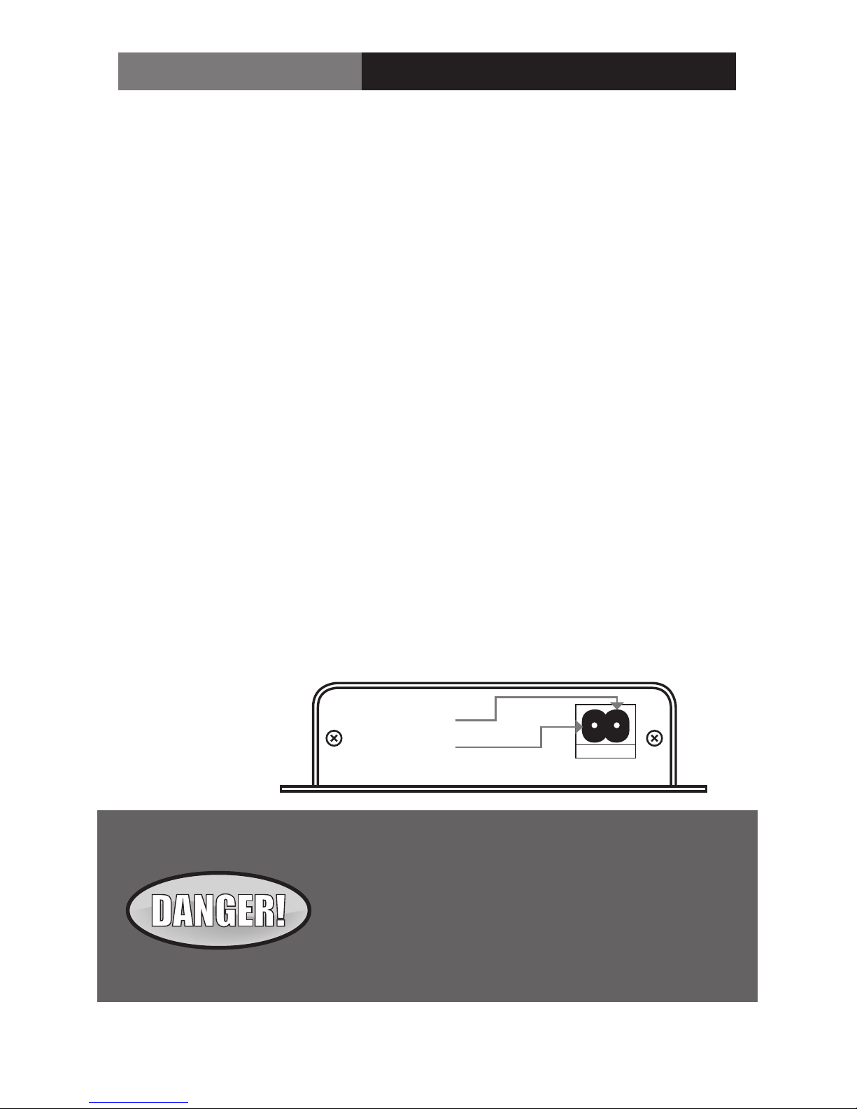
Figure 1:
Power Connector
DC Input Polarity
9-24 Volts
AC or DC
(+) Positive
( - ) Negative
Installation Instructions
The FiberLink 3500 Series of fiber optic transmission systems are ready for immediate use
and do not require any special tools or equipment. However, an Optical Power Meter, such
as the FiberLink 6650, can be useful in determining optical loss budgets during your systems
design and maintenance.
The following instructions describe the typical installation procedure:
1) Connect the fiber optic cable to the transceiver units.
2) Connect the video source to the video input BNC connector on the transmitter unit.
3) Connect the video output cable to video output BNC connectors on
the receiver unit.
4) Terminate any unused BNC output connector at 75 Ohms.
5) Connect the Universal Power Supply to the transmitter and receiver units.
For box versions using DC power, please refer to figure 1.
6) When power is applied, the green POWER LED should illuminate, indicating the
presence of operating power. The 3G/HD/SD RATE LED will give an indication as
described in the Indicator LED’s and Alarm Circuitry section of this manual.
7) The system should now be operational.
Note: The Rack Card version has an additional red LED for indicating the presence of an alarm
condition (loss of signal). Refer to Indicator LED’s and Alarm Circuitry sections of this manual.
Installation Instructions
The transmitting element in the FiberLink 3500 transmitter unit
contains a solid state Laser Diode located in the optical connec-
tor. This device emits invisible infrared electromagnetic radiation
which can be harmful to human eyes. The radiation from this opti-
cal connector, if viewed at close range with no fiber optic cable
connected to the optical connector, may be suicient intensity to
cause instantaneous damage to the retina of the eye. Direct view-
ing of this radiation should be avoided at all times!