artisan 1798-1 AZ User manual

Direct Drive Heavy Duty Top And Bottom Feed
Lockstitch Sewing Machine
1798-1 AZ
Instruction Manual
Parts Catalog
artisan Sewing Supplies, LLC San Francisco, CA USA 94103
artisan

----- CONTENTS -----
INSTRUCTION MANUAL
1. PRECAUTIONS BEFORE STARTING OPERATION ········································································1
2. SPECIFICATIONS······································································································································1
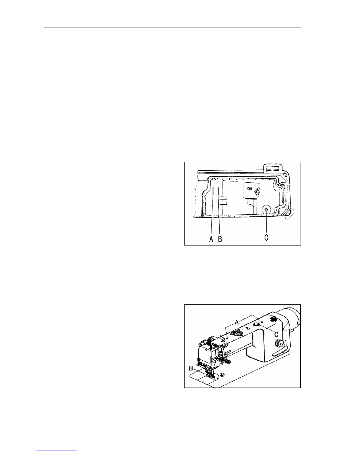
3. PREPARATION AND LUBRICATION···································································································2
4. PREPARETION BEFORE START TO OPERATE···············································································3
5. HOW TO USE THE MACHINE···············································································································4
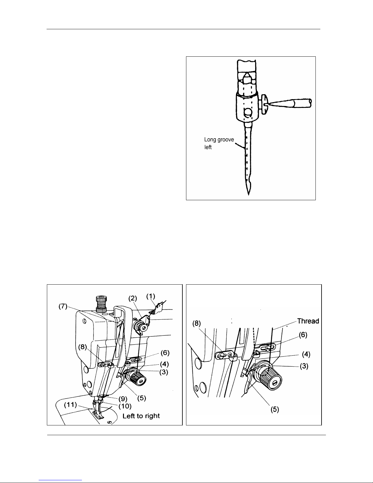
6. THREADING···············································································································································4
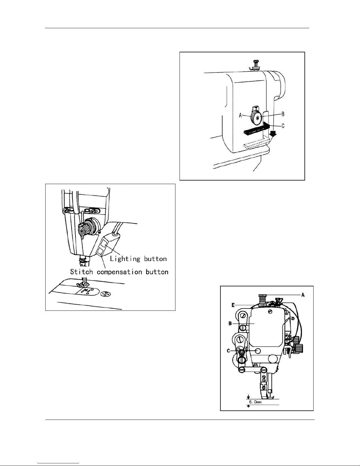
7. SET STITCH LENGTHAND REVERSE FEEDING···········································································5
8. POSITION PRESSER BAR·······················································································································5
9. ADJUST THE PRESSURE OF PRESSER EOOT·················································································6
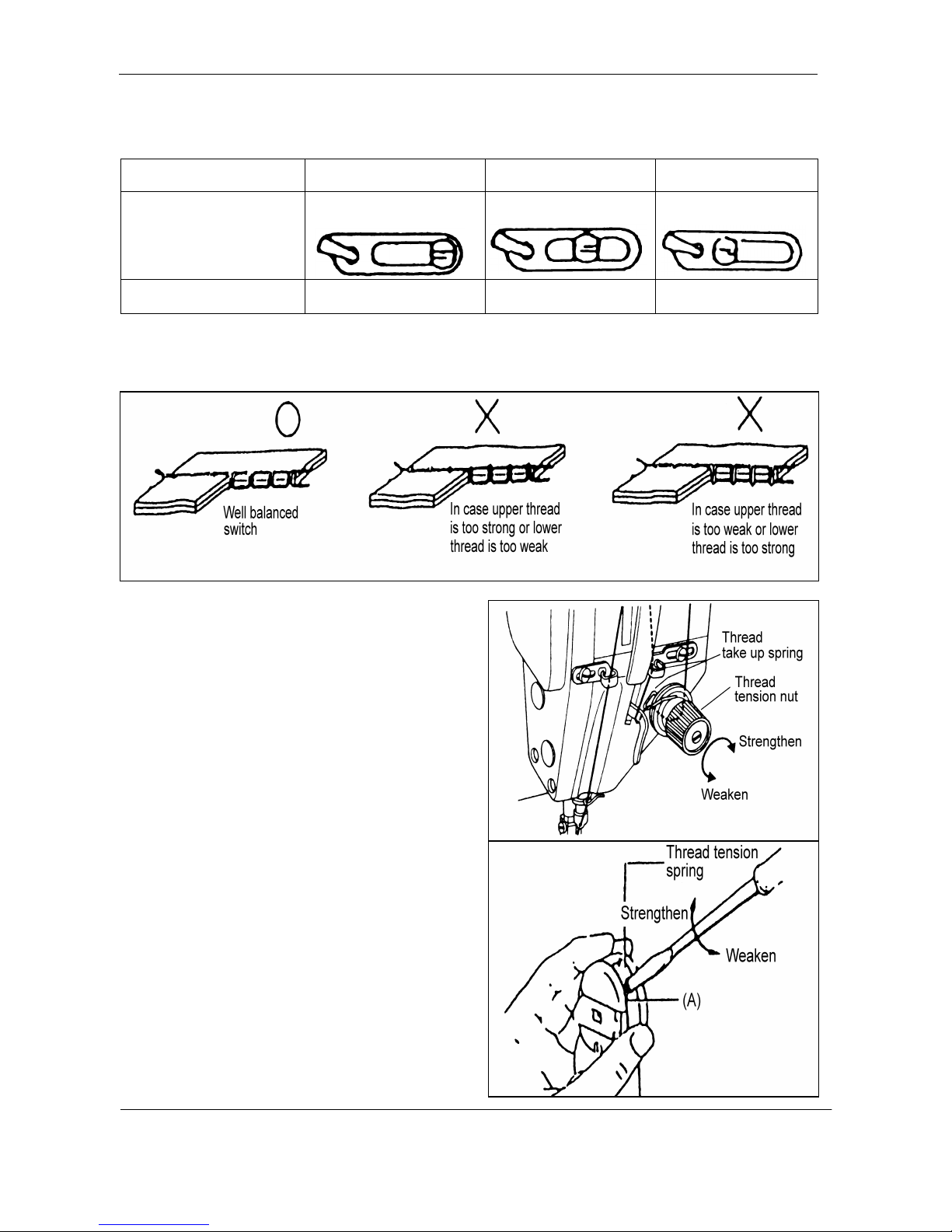
10. ADJUST THREAD TAKE-UPSPRING··································································································6
11. ADJUSTTHREAD GUIDEAND THREAD TENSION·······································································7
12. HOWTO WIND THE IOWER THREAD ON THE BOBBIN····························································8
13. TIME NEEDLE TO ROTAING HOOK ··································································································9
14. REPLACE ROTATING HOOK··············································································································10
15. ADJUST OPENINGTIME OFTHE TENSION DISCS·····································································10
16. ADJUST THE HEIGHT OF FEED DOG······························································································10
17. ADJUSTMENT OF FEED DOG INCLINATION················································································11
18. TIME FEED MOTION TO NEEDLE MOTION·················································································11
19. PERIODICALCLEANING·····················································································································12
PARTS CATALOG
A) ARM BED AND IT'S ACCESSORIES·····································································································13
B) NEEDLE BAR AND TAKE-UP LEVER & ARM SHAFT MECHANISM········································16
C) STITCH REGULATOR MECHANISM··································································································19
D) FEEDINGAND FEED LIFTING MECHANISM··················································································21
E) PRESSER FOOT MECHANISM··············································································································23
F) PRESSER LIFTING & FEEDING MECHANISM················································································25
G) OIL LUBRICATION MECHANISM········································································································28
H) MOTOR MECHANISM·····························································································································30
I) ACCESSORIES············································································································································32

—1—
1. PRECAUTIONS BEFORE STARTING OPERATION
1) Safety precautions
(1) When turning the power on, keep your hands and fingers away from the area around/under the needle
and the area around the pulley.
(2) Power must be turned off when the machine is not used,.
(3) The power must be turned off before tilting the machine head, installing or adjusting the machine, or
when replacing.
(4) Avoid placing fingers, hairs bars etc. nears the pulley, bobbin winder pulley, when the machine is
operation. Injury could result.
(5) Do not insert fingers into the thread take-up cover, under/round the needle, or pulley when the
machine is in operation.
(6) If a mini motor cover, finger guard, and/or eye guard are installed, do not operate the machine
without these safety devices.
2) Precaution before Starting Operation
(1) If the machine's oil pan has an oil sump, never operate the machine before filling it.
(2) If the machine is lubricated by drop oil, never operate the machine before lubricating.
(3) When a new sewing machine is first turned on, verify the rotational direction of the pulley with the
power on. (The pulley should rotate counterclockwise when viewed from the pulley.)
(4) Verify the voltage and (single or three) phase with those given on the machine nameplate.
3) Precaution for Operating Conditions
(1) Avoid using the machine at abnormally high temperature (35℃or higher) or low temperatures (5℃
or lower). Otherwise, machine failure may result.
(2) Avoid using the machine in dusty conditions.
2. SPECIFICATIONS
Material weight 1798-1 AZ
Max. speed 2000rpm
Stitch length 0 to 10mm
Needle bar stroke 35mm
Presser foot
clearance
Hand Lifter 6 mm
Knee lifter 13 mm
Needle type DP×17 #18~#22
Rotating hook Auto lubricated large hook for trimmer
Lubrication Auto lubricated
Motor 220V550W Servo motor

—2—
3. PREPARATION AND LUBRICATION
1) Cleaning the machine
Before leaving the factory, the machine parts are coated with rust-preventive grease, which may be
hardened and contaminated by dust during storage and shipment. This grease must be removed with gasoline.
2) Examination
Though every machine is confirmed by strict inspection and test before leaving the factory, the machine
parts may be loose or deformed after long distance transportation with jolt. A thorough examination must be
performed after cleaning the machine. Turn the balance wheel to see if there is running obstruction, parts
collision, uneven resistance or abnormal noise. If these exist, adjustment must be made accordingly before run-in
operation.
3) Oiling
(1) Required amount of oil. Line (A) on the oil reservoir:
Max. oil level. Line (B) on the oil reservoir: Min. oil level.
If oil level goes down under line (B), oil cannot be
distributed to each part of the machine, thus causing the
parts a seizure.
(2) Replenishing
Always use only No.18 special machine oil for high
speed sewing. Be sure to replenish oil to Line (A) before
starting operation.
(3) Replacing oil
To replace oil, remove Screw (C) to drain oil. After completely draining off oil, clean the oil reservoir and
securely tighten Screw (C), then fill the reservoir with fresh oil.
4) Run-in operation
Run-in operation is required for a new sewing machine, or a sewing machine left out operation for a
considerable length of time.
(1) Remove Red Rubber Plugs (A) on the top of the arm
and replenish sufficient amount of oil.
(2) Lift Presser Foot (B).
(3) Run the machine at a low speed (1000-1500spm) to
check oil distributing condition through Oil Check Window
(C).
(4) Perform run-in operation at 1000-1500spm for
30minutes. After a lapse of one month of service during
which the working speed is increased gradually and the machine runs sufficiently well, the high speed 2000spm

—3—
can be adopted according to the nature of the work.
5) Adjusting the lubrication of rotating hook
The lubrication of the rotating hook can be adjusted by Oil Adjusting Screw (A) as follows:
1) Turn Oil Adjusting Screw (A) clockwise to increase oil and turn Oil Adjusting Screw (A) counterclockwise to
decrease oil.
2) Oil Adjusting Screw (A) adjusts oil amount
within 5 turns. When Oil Adjusting Screw (A) is fully
tightened, oil amount is maximum.
3) Readjustment depends on temperature, sewing speed
and the like. In practice, oil amount can be judged as
follows: remove the throat plate and place a piece of
paper on instead, run the machine for about 20 seconds,
then check the oil splashed on the paper.
4.PREPARETION BEFORE START TO OPERATE
Adjustment of needle bar stop position Adjust of "UP" position
When the pedal is kicked down by heel, the machine stops at "UP" position. If the marks deviate larger than
3mm adjust as follows.
Release the set screw (1) of the magnet positioned piece, adjust the position of magnet positioning piece, until
the machine stops in the needle up position (the marker (A) and the marker point of motor cover to
coincide), then tighten the screw (1).

—4—
5. HOW TO USE THE MACHINE
How to attach needle
Note: Before making the following adjustment, be
sure to switch off the power source.
Insert the needle up to the bottom of needle clamp
and tighten the screw keeping the long groove
side of needle forward the left.
Note: if snapping of thread occurs during back
Sewing with polyester threads,it may be avoided
by fitting the needle with the long groove Shifted
to the front side.
6. THREADING
Raise the thread take-up lever to its highest position and thread the upper thread in the following order.
When draw the bobbin thread, hold the end of the needle thread and turn the balance wheel. Needle bar to the
lowest position and then lift it to its highest position. Pull the needle thread and the bobbin thread is drawn up.
Put the ends of needle thread and bobbin thread front ward under presser foot.

—5—
7. SET STITCH LENGTH &REVERSE FEEDING & Stitch compensation
1) Stitch length can be set by turning Dial (A).The
figures on Face (B) of dial show stitch length in mm.
2)Reverse feeding starts when Reverse Feed Lever (C)
is depressed, and the machine will feed forward again
if Reverse Feed lever (C) is released.
3) Stitch compensation switch
When the Stitch compensation button is pressed
lightly during sewing, Stitch compensation sewing can
be done.
When the button is released, Stitch compensation
sewing is end.
8. POSITION PRESSER BAR
1) Loosen lock Nut (E) and Pressure Regulating Thumb Screw (A).
2) Remove rubber plug from Face Plate (B).
3) Loosen Screw (C) and adjust the position of Presser Bar (D) till
the presser foot is 6 mm above the throat plate, the presser foot
lifted to its highest.
4) Tighten Screw (C) and put in the rubber plug.
5) Tighten pressure Regulating Thumb Screw (A) and Lock Nut (E).

—6—
9. ADJUST THE PRESSURE OF PRESSER EOOT
Pressure of presser foot is to be adjusted in
accordance with thickness of materials to be sewn.
First loosen Lock Nut (A). For heavy materials, turn
the pressure regulating thumb screw as shown in Fig.10
(a) to increase the pressure, while for light materials, turn
the pressure regulating thumb screw as shown in Fig.10
(b) to decrease the pressure. Then tighten Lock Nut (A).
The pressure of presser foot is recommended to be
less as long as normal feeding is ensured.
10. ADJUST THREAD TAKE-UP SPRING
1)Adjusting the thread take-up spring tension
Loosen Set Screw (A), turn Tension Stud (B) clockwise
to increase the spring tension, or turn the stud
counter-clockwise to decrease the spring tension. After the
adjustment, be sure to tighten Set Screw (A). The thread
take-up spring tension should be about 30g. To attain this.
First loosen Set Screw (A), turn Tension Stud (B)
counter-clockwise to decrease the tension of Thread Take-up
Spring (C) to zero, then turn Tension Stud (B) clockwise
until Spring (C) comes to the notch of thread tension
regulating bushing, and again turn Tension Stud (B) halfway
back (counterclockwise) After the adjustment. Tighten Set
Screw (A).
2)Adjusting the thread take-up spring stroke
Loosen Set Screw (B), turn Stud (C) clockwise to
increase the stroke or turn Stud (C) counter-clockwise to
decrease the stroke. After the adjustment, tighten Set Screw
(B).
Before leaving the factory, the thread take-up spring
has properly been adjusted. Readjustment is needed only in
the case of special material or special thread.

—7—
11. ADJUST THREAD GUIDE AND THREAD TENSION
1) Adjusting of the thread guide
1 2 3
Thread guide position
Left Middle Light
Materials Heavy Medium Light
Refer to the table above, and adjust according to the stitching conditions, the material and thread
2) Adjusting of thread tension
3) Adjusting of upper thread tension
(1) Upper thread tension can be adjusted by thread
tension nut.
(2) Upper thread is to be adjusted according to the
lower thread tension.
(3) For special fabric sewing with special thread, the
desired tension can be obtained by adjusting the strength
and operating range of thread take-up spring.
4) Adjusting of lower thread tension
(1) Lower thread tension can be adjusted by
the screw (A).

—8—
(2) The thread tension can be checked as the following.
Hold the end of pulled out thread and if the bobbin case
fall slowly, the tension is proper.
12. HOW TO WIND THE IOWER THREAD ON THE BOBBIN
1) Press the bobbin onto the thread winding shaft.
2) Pass the thread for winding thread as shown in the
figure, and wind the end of the thread clockwise around
the bobbin several times, then wind the thread on the
thread adjuster side counter-clock wise several times.
3) Press lever ①in the direction of the arrow, and start
the sewing machine.
4) The operation will automatically stop when winding is
completed.
5) Adjustment of thread winding strength
Adjust with the thread adjuster nut ②.
6) Adjustment of thread winding amount
Adjust by loosening screw ③and moving the
adjustment plate ④

—9—
13. TIME NEEDLE TO ROTAING HOOK
A. Adjusting the needle position
1) Turn balance wheel by hand to bring Needle Bar (C) to the lowest position of its stroke.
2) Remove rubber plug from Face Plate (A).
3) Loosen Set Screw (B) of needle bar adaptor.
4) Move Needle Bar (C) vertically to adjust needle timing.
5) After the adjustment, tighten Set Screw (B) and put in the rubber plug. The standard needle timing is to align
Timing Mark (E) on the needle bar and the bottom of Needle Bar Bushing (D) and meanwhile align the Inner
Surface (G) of the hook and the center of Needle Eye (F) when the needle bar gets down to its lowest position.
B. Adjusting the hook point timing
Timing of needle motion to rotating hook motion has a great effect on sewing performance. The standard
hook point timing is to align Hook Point (D) and Needle Centerline (C) when Needle Bar (B) is lifted by 2.2mm
from the lower end of its stroke. Besides, Hook Point (D) should be 1.0-1.5mm above the upper end of needle
eye (E).
When adjusting the hook point timing, also notice that the clearance between the bottom of needle notch (F)
and Hook Point (G) should be approx. 0.05mm.

—10 —
14. REPLACE ROTATING HOOK
1) Lift needle bar to the highest position of its stroke.
2) Remove throat plate, take down needle and bobbin case.
3) Loosen Screw (C) of hook position and take down Hook
Position (B).
4) Loosen two Screws (D) of rotating hook.
5) Turn balance wheel to raise feed bar to its highest
position, then take down the rotating hook by turning it
away from feed bar.
6) Installing the hook can be done in reverse sequence.
Note that Needle (A) and the convex surface of Hook
Position (B) should align with a clearance of 0.5-0.7mm
between them.
15. ADJUST OPENING TIME OF THE TENSION DISCS
Within the presser foot lift range of
2-7mm opening time of the tension discs
can be adjusted as follows:
1) Remove the rubber plug from the back
of arm and loosen Screw (A) of knee lifter
lever (left).
2) Move the tension releasing cam
leftward for earlier opening or rightward for
later opening. It will facilitate the
adjustment to put under the presser foot a
block as thick as the presser foot lift.
3) After the adjustment, fully tighten
Screw(A).
16. ADJUST THE HEIGHT OF FEED DOG
1) Turn balance wheel until feed dog is lifted to its highest position from throat plate surface.
2) Loosen Screw (A) of feed lifting rock shaft crank right
3) Move Feed Bar (B) in the direction shown by the arrow to adjust the height of the feed dog. The standard
height of feed dog is that the top of feed dog is 1mm above Throat Plate Surface (B).

—11 —
4) After the adjustment, be sure to tighten Screw (A).
17.ADJUSTMENT OF FEED DOG INCLINATION
If necessary, adjust the inclination
according to the material to be sewn as
follows:
1) Loosen the screw “A”.
2) Rotate the eccentric shaft clockwise or
counterclockwise with screw driver.
3) Tighten the screw “A”.
18. TIME FEED MOTION TO NEEDLE MOTION
The standard timing of feed motion to needle motion
is that the top of feed Dog (C) is flush with Throat Plate
Surface (B) when the point of Needle (A) reaches Throat
Plate Surface (B).

—12 —
If feed motion is not timed to needle motion, adjust as follows
1) Remove Arm Side Cover .
2) Loosen Set Screws (A) and (D) of feed and feed lifting eccentric.
Hold Feed and Feed Lifting Eccentric (B) and turn Balance Wheel slowly until the upper edge of Arm Shaft Oil
Hole (C) aligns with the lower edge of Reference Hole (G) of feed and feed lifting eccentric.
Leave a clearance of 0.3-0.5mm between Feed and Feed Lifting Eccentric ( B ) and Eccentric Sleeve ( H ), then
tighten Set Screws ( A ) and ( D ).
19.PERIODICAL CLEANING
A. Machine
1) Remove the throat plate and clean the feed dog.
2) Assembling is to be made by screwing in the screw by 2
to 3rotations by hand at first, then tightening them evenly by
use of a long size screw driver.
3) Lay down the machine head and clean the hook and
inner bobbin case.
B. Maintenance of motor
Remove dust from the motor cover every one or two
month. (If operation is continued with the motor cover
clogged with lint or dust, the motor might overheat.)
C. Control box
Remove dust from the connector (If the connector
covered with dust, machine might misoperation )
D. Cleaning oil pump, screen
Swing out the machine head and clear off the dust and
dirt on oil pump screen.

A.ARM BED AND IT'S ACCESSORIES
─ 13 ─

Fig.
No. Part No. Description Pcs. Remarks
A01 HDB6057101 Arm 1
A02 HDB6098001 Trade mark plate 1
A03 H924025050 rivet 2φ2.5×5
A04 HA106B0676 Thread guide screw 2SM9/64″×40
A05 HA607B0671 Thread guide on face plate 1
A06 HA307B0674 Rubber plug (φ11.8 ) 4
A07 HA700B2030 Face plate screw 2SM11/64″×40
A08 HM310B8001 Face plate 1
A09 HA307B0673 Rubber plug (φ19)3
A10 HA300B2090 Rubber plug (φ8.8)3
A11 HA300B2110 Rubber plug (φ5.7)1
A12 HA700B2060 Set screw 1
A13 HA700B2050 Three-hple thread guide 1
A14 HY91B37101 Bobbin winder assy 1
A15 H2400I2080 Set screw 3
A16 H6028B8001 Arm side cover 1
A17 HA300B2170 Screw group 9
A18 H6029B8001 Gasket for arm side cover 1
A19 H1210B0671 Check window 1
A21 HA710B0671 Nut 1
A22 H6739B8001 Thread tension spring 1
A23 HA310B0705 Thread tension disc 4
A24 H6735B8001 Thread tension stud 1SM15/64″×28
A25 H6736B8001 Thread guide 1
A26 H6737B8001 Spacer 1
A27 H6030B8001 Rubber plug (φ22)1
A28 HDK6138001 Integrally motor cover 1
A29 HA300B2100 Rubber plug (φ27)1
A30 HA100B2220 Leg 3
A31 HA100B2110 Set screw 1SM11/64″×40
A32 H6762B8001 Screw 2
A33 H6756B8001 Thread cutter 1
A34 HA600B2050 Thread guide at arm center 1
A35 HA300B2080 Set screw 1SM15/64″×28
A36 HA300B2130 Screw 2SM11/64″×40
A37 HA300B2140 Plate for guide 1
A38 HA710B0674 Pre-tension thread guide 1
A39 HA710B0673 Screw type tension stud 1SM11/64″×40
A40 HA112B0693 Disc for pre-tension 2
A41 HA710B0672 Spring for pre-tension 1
A42 HA710B0671 Nut 1
A43 H005008060 Spring washer 2
A44 HA124B0711 Slide plate 1
─ 14 ─
A.ARM BED AND IT'S ACCESSORIES

Fig.
No. Part No. Description Pcs. Remarks
A45 HA300B2190 Needle plate screw 2SM11/64″×40
A46 H1100B2060 Needle plate 1
A47 HA324B0711 Slide plate spring 1
A48 HA124B0713 Screw 2
A49 HA115B0708 Screw 1
A50 HA115B7011 O-ring 1
A51 HA310B0703 Thread tension regulating bushing 1
A52 HA505B0672 Thread take-up spring 1
A53 HA115B0701 Screw type tension stud 1
A54 HA115B0709 Thread tension releasing pin 1
A55 HA310B0702 Thread tension releasing disc 1
A56 HA505B0671 Thread tension spring 1
A57 HA115B7010 Stop disc 1
A58 HA310B0701 Oil thumb nut 1
A59 HZ11050200 Screw 3
A60 H6409B8001 Arm bed cover( left ) 1
A61 H6410B8001 Gasket for arm bed cover 1
─ 15 ─
A.ARM BED AND IT'S ACCESSORIES

B.NEEDLE BAR AND TAKE-UP LEVER & ARM SHAFT MECHANISM
─ 16 ─

Fig.
No. Part No. Description Pcs. Remarks
B01 HA300C2050 Rubber plug 1
B02 HA100C2100 Felt plug 1
B03 HA100C2080 Needle bar bushing ( upper ) 1
B04 H2100C2010 Needle bar 1
B05 HA804B0652 Needle bar bushing ( lower ) 1
B06 HA500C2060 Thread guide for needle bar bushing 1
B07 HA500C2030 Thread guide for needle bar 1
B08 Needle 1DP×17 #22
B09 HA100C2170 Needle clamp screw 1SM1/8″×44
B10 H11112C104 Thread take-up lever link 1
B11 HA504C0651 Thread take-up crank 1
B12 H2004H0067 Set screw ( left-handed ) 1SM9/64″×40
B13 HA304C0653 Needlc bar link 1
B14 HA106B0676 Screw 1SM9/64″×40
B15 HA104C0658 Needle bar adaptor 1
B16 HA100C2190 Set screw 2SM11/64″×40
B17 HA100C2200 Slide block 1
B18 HA100C2180 Guide for slide block 1
B19 HA307C0662 Set screw 2SM1/4″×40
B20 HA100C2060 Set screw 1SM9/32″×28
B21 HA100C2020 Set screw 1SM15/64″×28
B22 HA104C0653 Hinge pin 1
B23 H11111C104 Therad take-up lever 1
B24 HA100C2070 Set screw 1SM9/32″×28
B25 HA307C0661 Needle bar crank 1
B26 HA104D0652 Rubber plug ( Ф7.4×10 ) 1Φ7.4×10
B27 HA100D2030 Arm shaft bushing(left) 1
B28 HDD6058001 Arm shaft 1
B29 H5349B8001 Set screw 2SM11/64″×40
B30 HA100C2020 Set screw 1SM15/64″×28
B31 HA100D2040 Arln shaft bushing(middle) 1
B32 HA105D0662 Set screw 2SM1/4″×40
B33 HA108G0661 Collar for 1
B34 HA108C0663 Set screw 8M1/4″×40
B35 HA113D2112 Bevel gear for arm shaft 1
B36 HA112D3012 Retaining ring 1
B37 H38111D104 Feed and feed lifting eccentric 1
B38 H38111D204 Slider 1
B39 HA3411D308 Set screw 2
B41 HY91B28001 Bobbin winder driving wheel 1
B42 HA113D2122 Bevel gear for vertical shaft( upper ) 1
B43 HA100C2020 Set screw 2SM15/64″×28
B44 HA100D2110 Vertical shaft bushing( upper ) 1
─ 17 ─
B.NEEDLE BAR AND TAKE-UP LEVER & ARM SHAFT MECHANISM

Fig.
No. Part No. Description Pcs. Remarks
B45 H2100D2010 Vertical shaft 1
B46 HA600D2010 Vertical shaft bushing( lower ) 1
B47 HA113D2222 Bevel gear for vertical shaft( lower ) 1
B48 HA113D2212 Bevel gear for hook shaft 1
B49 H3800D2020 Feed forked connection 1
B50 HA112D3013 Crank rod for feed lifting rock shaft 1
B51 H2100E2010 Rotating hook positioner 1
B52 HA100E2150 Screw 1SM11/64″×40
B53 HA100E2040 Hook shaft bushing (left) 1
B54 HA904E0651 Hook shaft 1
B56 HA305E0662 Set screw 2SM15/64″×28
B57 HA305E0661 Collar for hook shaft 1
B58 HA311E0671 Hook shaft bushing ( right ) 1
B59 HA110E0672 Oil pipe for hook shaft bushing 1
B60 HA300E2100 Plunger 1
B61 HA608E0067 Bobbin case 1
B62 HA600E2060 Bobbin 1
B63 H1105E0065 Rotating hook complete 1
B64 HA1111E104 Filter screw 1
B65 HA1111E204 Filter 1
B66 HA106E0071 Oil seal for rotating hook shaft 1
B67 HA100E2060 Spring for oil adjuster 1
B68 HA100E2050 Oil adjusting screw 1
B71 HA300E2110 Plunger spring 1
B72 HA600E2020 Guide plate 1
B73 HA104F0654 Screw 1SM15/64″×28
─ 18 ─
B.NEEDLE BAR AND TAKE-UP LEVER & ARM SHAFT MECHANISM
Table of contents
Other artisan Sewing Machine manuals

artisan
artisan 1988-MDZ User manual

artisan
artisan 2698-1 User manual

artisan
artisan VME-SIO4A User manual

artisan
artisan 196 R-2 Guide

artisan
artisan 797 AB-800 User manual

artisan
artisan 1508 H-10 User manual

artisan
artisan 8144-20 User manual

artisan
artisan 45K-2 User manual

artisan
artisan 4618 Guide

artisan
artisan TORO 4011 LA-37 User manual

artisan
artisan TK-117 User manual

artisan
artisan 880 User manual

artisan
artisan Toro 4500 Guide

artisan
artisan 4400RB Guide

artisan
artisan 1797 AB Guide

artisan
artisan Toro-4600 Product manual

artisan
artisan WM217 Technical manual

artisan
artisan 20-53 Guide

artisan
artisan 2618-1B Instruction Manual

artisan
artisan 797 ab series Guide