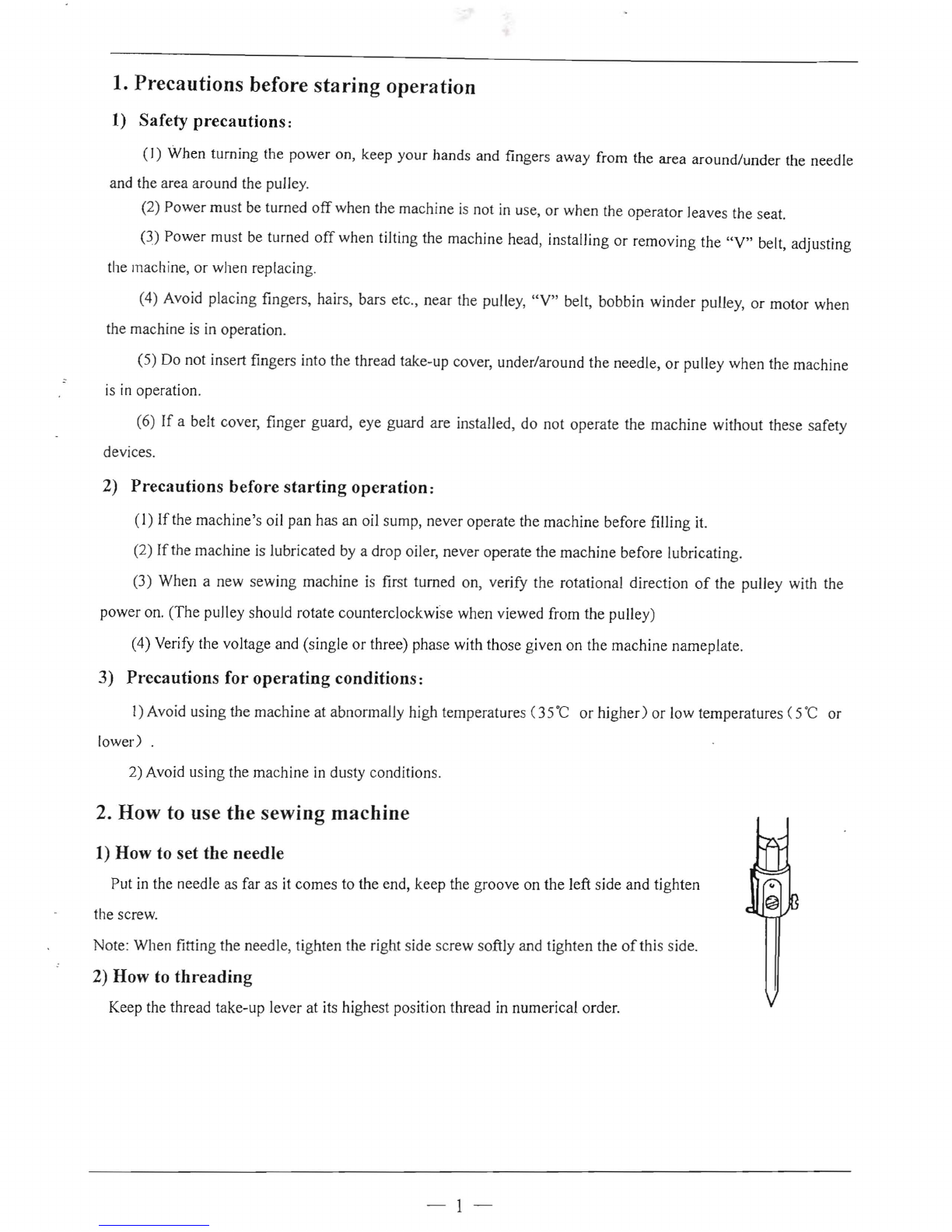
(4) When the small looper is in its left most position, the position
of
the slot bottom in the small looper
must come out I to 2mm from the side face
of
the hook needle as illustrated in
Flg.Ll
.
If
this projection is
excessive, the chain-off thread will be difficult to come out. To adjust the
position
of
the small looper, loosen the setscrew in the small looper block as
illustrated in
Fig.n.
Fig
,12
Fig.11
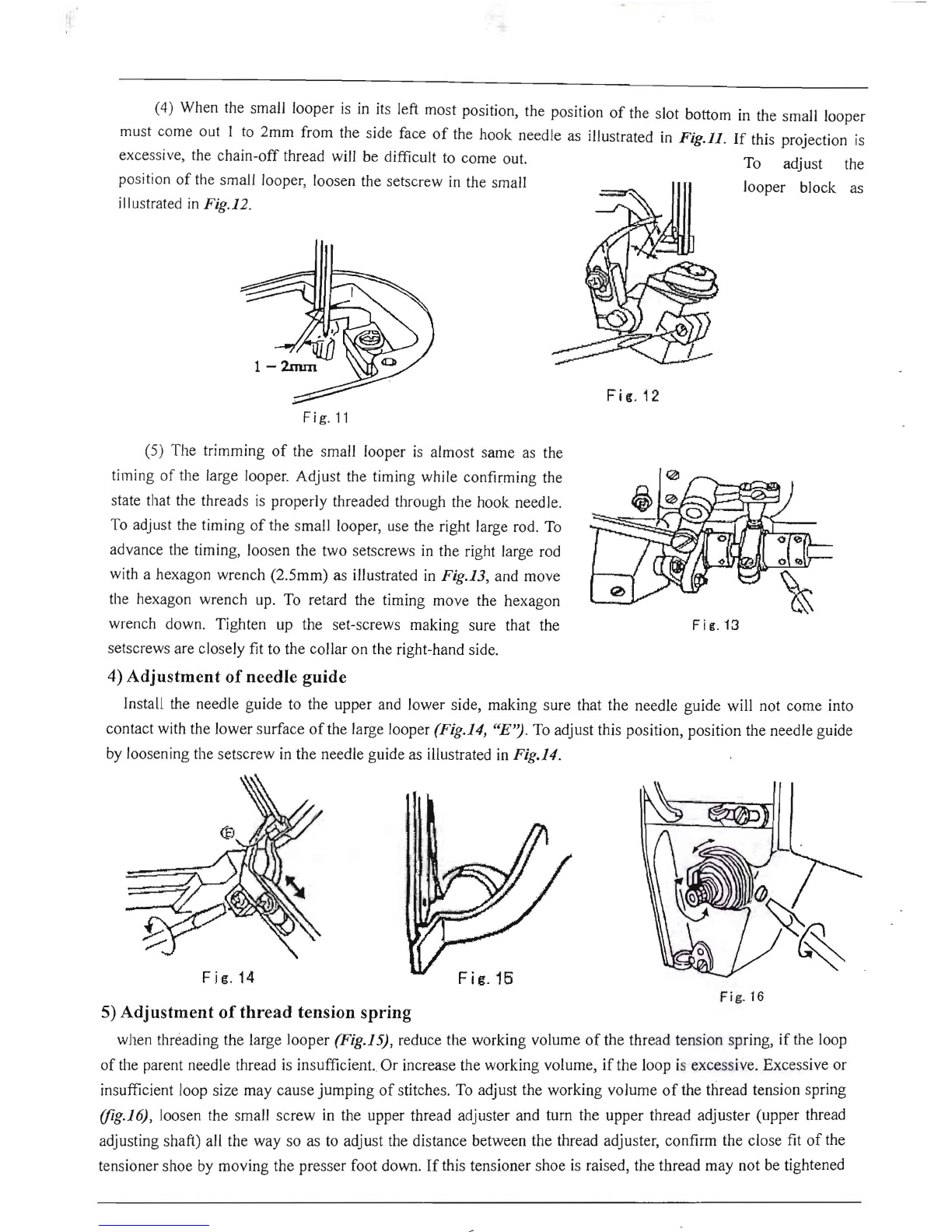
(5) The trimming
of
the small looper is almost same as the
timing
of
the large looper. Adjust the timing while confirming the
state that the threads is properly threaded through the hook needle.
To adjust the timing
of
the small looper, use the right large rod. To
advance the timing, loosen the two setscrews in the right large rod
with a hexagon wrench (2.5mm) as illustrated in Fig.13, and move
the hexagon wrench up. To retard the timing move the hexagon
wrench down . Tighten up the set-screws making sure that the
setscrews are closely fit to the collar on the right-hand side.
4)
Adjustment
of
needle guide
Install the needle guide to the upper and lower side, making sure that the needle guide will not come into
contact with the lower surface
of
the large looper (Fig.14,
"E")
. To adjust this position, position the needle guide
by loosening the setscrew in the needle guide as illustrated in Fig.14.
F j it. 13
I~l
Fig
.16
F j g. 14
Fig.16
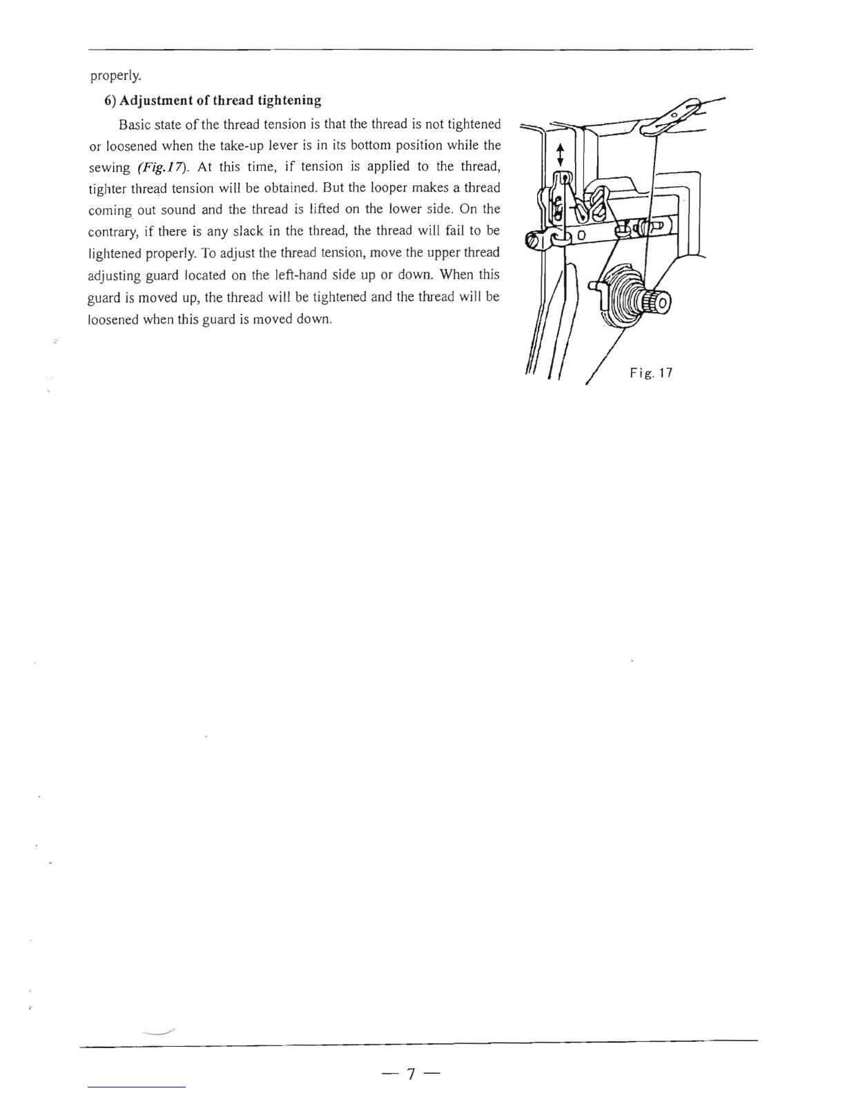
5)
Adjustment
of
thread
tension
spring
when threading the large looper (Fig.IS}, reduce the working volume
of
the thread tension spring, if the loop
of
the parent needle thread is insufficient. Or increase the working volume, if the loop is excessive. Excessive or
insufficient loop size may cause
jumpin
g
of
stitches. To adjust the working v
olume
of
the thread tension spring
(fig.Iti), loosen the small screw in the upper thread adjuster and turn the upper thread adjuster (upper thread
adjusting shaft) all the
way
so as to adjust the distance between the thread adju
ster
, confirm the close fit
of
the
tensioner shoe by moving the presser foot down.
If
this tensioner shoe is raised, the thread may not be tightened