Artistic Licence Rail-Switch II User manual

Artistic Licence
Rail-Switch II User Guide
Rail-Switch II
Version 5-6
User Guide

Page 2
Rail-Switch II User Guide
Please read these instructions before using the product.
This product has been designed & manufactured for professional use only.
It should only be installed by a suitably qualied technician and in accordance with
electrical regulations in the country of use.
Unless directed in the instructions there are no user serviceable parts inside the
outer case of this product.
Always disconnect from the power supply when not in use.
Any specic IP rating, where appropriate, is given in the instructions. Unless
otherwise stated this product is designed for indoor use only. If used outdoors it
MUST be installed in an appropriate IP rated cabinet. Do not allow this product to be
exposed to rain or moisture. Do not allow liquid to penetrate the product.
Please recycle all packaging.
Copyright © Artistic Licence Engineering Ltd. All rights reserved.
Download the user guide by scanning the following QR code:

Page 3
Rail-Switch II User Guide
Reference Type Description
1LED Data type
2LED Power/
RDM locate
3Connection Power Input
4Connection DMX512 Input
5Connection DMX512 Loop &
Term
6Connection Relay Outputs
7LED Relay energised
Connections
Mounting Diagram
DMX512 Wiring
XLR Pin
(Convention)
Function Colour
1Ground Black
2Data - Blue
3Data + Red
Circuit Description
DMX512 Input
(including Loop Through)
Type: Non-isolated
Pin 1: Connects to Internal Logic
Ground
Relay Outputs Isolated, volt-free
Internal Logic Ground Connects to Ground Power Input
Internal Earth and Isolation
** A passive loop-through connection allows
onward connection to other DMX512 devices. If
this feature is not required then the signal must
be terminated. The product contains an internal
termination resistor. This is enabled by tting a
wire link between Term and DAT+.

Rail-Switch II User Guide
Overview
Page 4
Connections
Input
The DMX512 input is attached via a 3-pin
screw terminal. Please refer to the connections
diagram.
Loop Through
A passive loop-through connection allows
onward connection to other DMX512 devices.
If this feature is not required then the signal
must be terminated. The product contains an
internal termination resistor. This is enabled by
tting a wire link between the screw terminals
that will terminate the DMX line (Term and
DAT+).
In theatre, touring and architectural
applications there are invariably some devices
that do not provide a useful form of remote
control. Rail-Switch II is an elegant solution
to the automation of these devices.
Rail-Switch II is a DIN Rail mounted device
that provides 6 mains voltage relays and is
controlled via DMX512 & RDM. Each relay
can be switched independently. The product
is powered via an external DC power supply
unit.
The product is congurable using RDM. This
is particularly useful in enabling the start
address of each relay to be set individually.
Summary of Key Features
y6 mains relays
yRelays rated at 250V AC, 8A non-
inductive
yDMX/RDM controlled
yLED indication for data, power and each
relay output
ySimulated RDM sub-devices for start
address programming
yPreset mode eliminates need for DMX
controller
yData loss and test modes
yDIN Rail or surface mount
Power
Rail-Switch II is be powered from an
external DC power supply (9-24 VDC). It is
recommended that a ferrite core be tted onto
the DC power lines as close as possible to the
Rail-Switch II. This protects the unit from any
electrical spikes that appear on the DC line.
Output
Six relay outputs are provided. It is
recommended that the output wires are tted
with separate ferrite cores when driving a high
current load.
Relays
NC NO
C
The relays energise at a DMX value of 128.
Each relay has three connections; Common,
Normally Open and Normally Closed.
Common (C)
This connection is always used and is
connected to either the open or closed pin
depending on the state of the relay.
Normally Closed (NC)
This pin is connected to
Common when the relay is
not energised.
Normally Open (NO)
This pin is not normally
connected to the Common
pin. The relay must be
energised for a connection
to be made.
Loading
Rail-Switch II uses electromechanical relays
that are rated for 8A at 250 VAC when
switching non-inductive loads. The product
can be used to drive inductive loads, or those
with high inrush currents, so long as external
surge protection is added. These devices stop
the contacts from being damaged by arcing.
Part code ‘Sequence-Filter’ is an external
PTC lter suitable for this purpose.
The user must also ensure that external circuit
protection such as circuit breakers or fuses
are connected in compliance with the local
wiring regulations.

Page 5
Rail-Switch II User Guide
Conguration
Rail-Switch II uses one channel to control
each relay, requiring 6 channels in total.
There are various conguration options
(including start address programming). These
are accessed using RDM, which requires a
suitable programming interface.
One option is Commissioner rdmx, a handheld
RDM programming tool available from Artistic
Licence.
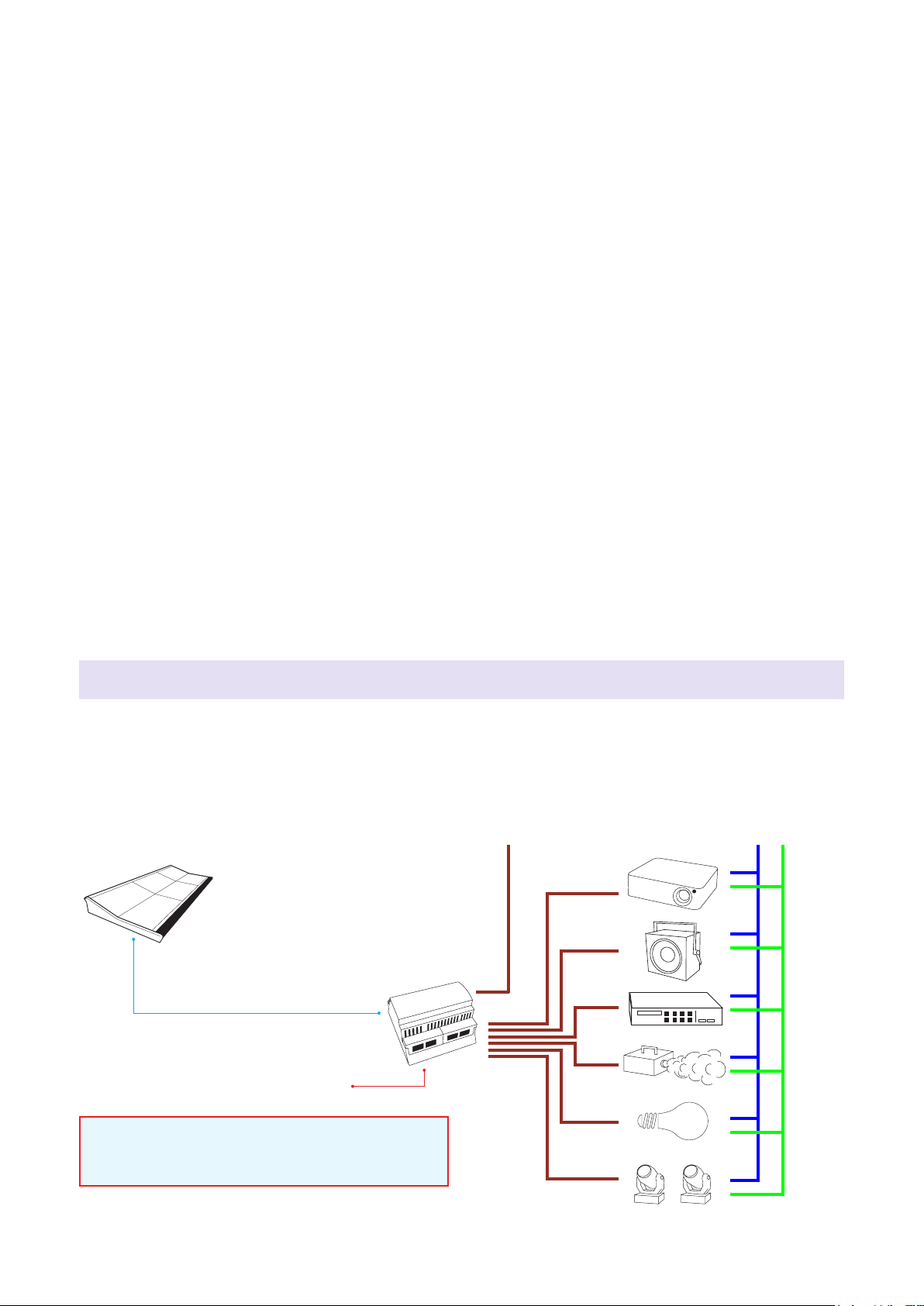
Alternatively, Rail-Switch II can be connected
to an Art-Net network using an interface
product such as Art-Lynx O/P or Net-Lynx
O/P. Conguration is then achieved using
DMX-Workshop, a PC software application
for managing Art-Net networks (available as
a free-of-charge download from the Artistic
Licence website, www.artisticlicence.com).
Rail-Switch II has front-panel LED indicators
for the following functions:
Data (upper):
OFF = no data received
Green = DMX and RDM received
Yellow = DMX only received
Alternating green/yellow = Rail-Switch II is
in preset playback mode or test mode (see
‘Conguration’ below)
Power/Locate (lower):
Green = Power
Flashing green = RDM locate is active
An RDM locate sent to the root or the sub-
devices will have the identical eect of causing
the power indicator to ash.
Relays 1 - 6 (right-hand side):
Blue = Relay is energised
This windows-based application provides a
convenient means of accessing the Rail-Switch
II conguration menus. DMX-Workshop can
also be used for product rmware uploads.
Preset mode
It is possible to pre-programme Rail-Switch
II such that it can be installed without a DMX
controller. Rail - Switch II has 8 preset memories
which can be used to record dierent on/o
combinations of the six relay outputs.
DMX-Workshop allows these settings to be
captured and played back. To access the
relevant menus, right-click on the Rail-Switch
II RDM device (as shown above). Please note
that the data captured is always the DMX512
input, independent of the currently selected
output.
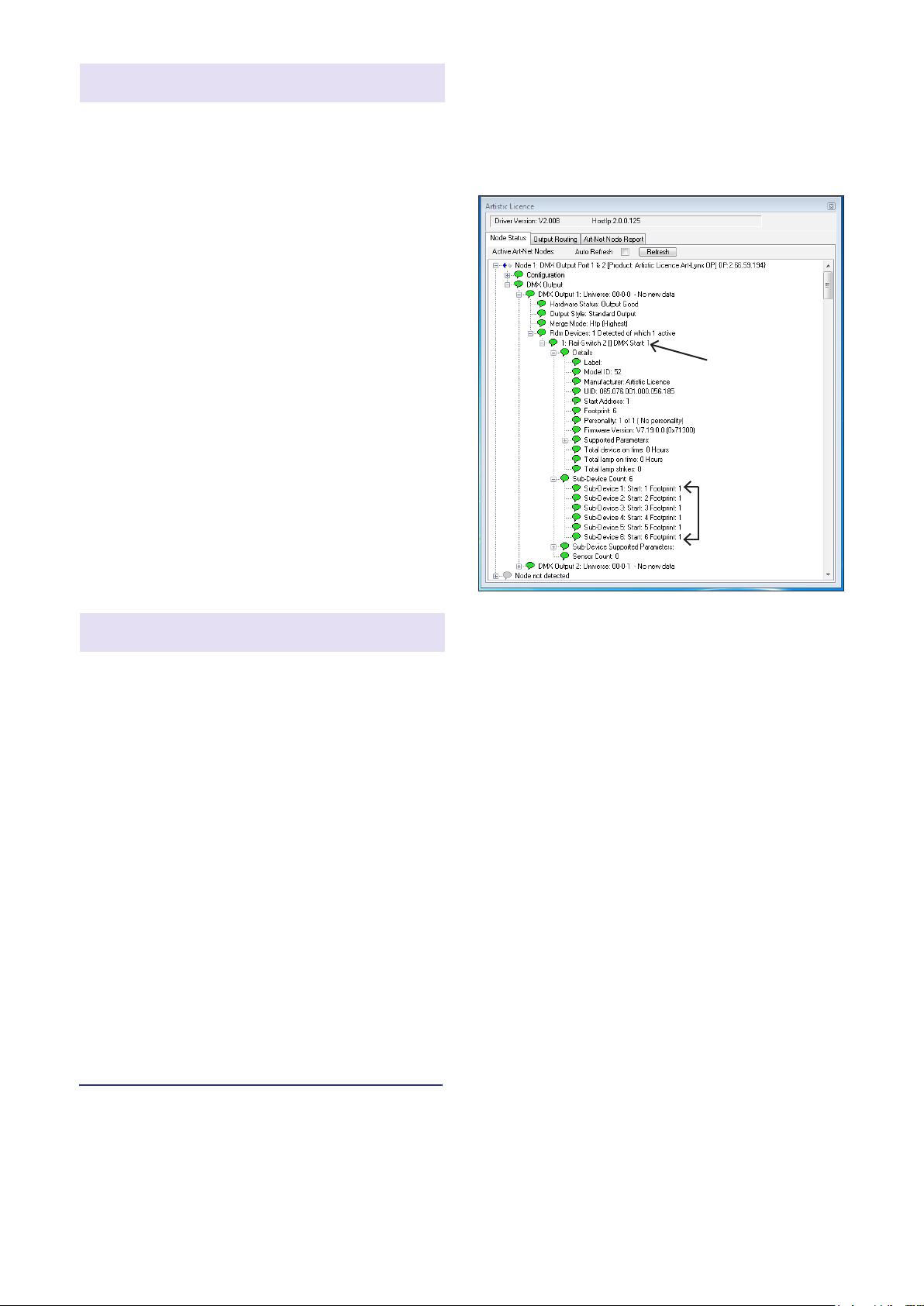
LED Indication Start address programming
In the DMX-Workshop ‘Node List’ screen,
Rail-Switch II appears as an RDM device,
with each relay listed as a sub-device (see
screenshot below).
DMX-Workshop
If the user wishes all 6 output channels to be
consecutively addressed, this is achieved by
setting the RDM device start address (right-
click on the RDM device entry). Alternatively, if
the user wishes to individually set the address
of each channel, this is achieved by setting
the start address of each sub-device (right-
click on the desired RDM sub-device).
Generally, right-clicking on any entry brings
up a menu of the available options.
RDM device
RDM
sub-device

Page 6
Rail-Switch II User Guide
The diagram below shows how Rail-Switch II could be utilised in a typical application. The DMX
controller is not required if the Rail-Switch II has been preset programmed using RDM, or if it
is in test mode.
Application Diagram
Rail-Switch II
DMX512
DMX controller
DC power in
Live - Supply
Live - FeedLive - Feed
Earth
Neutral
It is recommended that inline current-limiting
lters (e.g. Sequence-Filter) are used to protect
the relays in Rail-Switch II for all inductive loads.
Data loss mode
DMX-Workshop (or a suitable RDM tool) also
allows programming of data loss mode. This
mode is intended to be used when Rail-Switch
II is being controlled by DMX (i.e. when it is
not running in preset mode).
The data loss programming determines what
Rail-Switch II should do if DMX is lost for
more than 2.5 seconds. It can be selected to
play one of the 8 presets or hold the last state.
If DMX returns, the control is immediately
returned. Rail-Switch II will also power up in
this mode until DMX is detected.
To access the data loss mode menu, right-
click the Rail-Switch II RDM device, then go
to Advanced - Artistic Licence products - Data
loss mode.
The priority of output is as follows (highest at
the top):
1. Test pattern
2. Preset playback
3. Data loss event
4. DMX512
Test mode
Output priority
Rail-Switch II oer two test patterns:
Test 1 = all outputs on
Test 2 = all outputs o
DMX-Workshop (or suitable RDM tool) can be
used to put the product in test mode, which
can be useful during show commissioning or
rehearsals.
To access the data test mode selections,
right-click the Rail-Switch II RDM device, then
go to ‘Self test’.
Preset playback is non-volatile. This means
that if a preset is played back, Rail-Switch
II can be then disconnected from DMX and
power cycled and will still playback the preset.

Page 7
Rail-Switch II User Guide
Rail-Switch II Specication
Mechanical
yHousing: DIN Rail Case
yMaterial: Polycarbonate plastic, UL94-V0
rated
yOverall dimensions: 90 mm (H) x 88 mm
(W) x 62 mm (D)
yWeight: 0.2 kg
yMounting: 35 mm DIN Rail or Surface
Mount
yCountry of manufacture: UK
Environmental
yOperating temperature: 0°C to 40°C
yStorage temperature: -10°C to +50°C
yOperating relative humidity (max): 80%
non-condensing
yIP rating: IP20 indoor use only
yCertication: CE, WEEE, RoHS
yWarranty: 2-year (return to base)
Power & Electrical
yInput voltage: 9-24 VDC
yInput connector: 2-pin pluggable screw
terminal (1 no.)
yInput power (max): 10 W
yDuty cycle: 100% @ 25°C
yDC fuse: internal resettable fuse for
control electronics
DMX512 input
yInput mode: Non-isolated
yInput ESD protection: 12 kV
yInput voltage protection: +/- 80 V
Data Connection
y3-pin Screw Terminal DMX Input (1 no.)
y4-pin Screw Terminal DMX Loop / Term
(1 no.)
LED Indication
yPower / DMX / RDM / Preset / Test / RDM
locate / Relay
Conguration
yCommissioner, DMX Workshop
yCongurable settings include:
- Start address (individual for each relay)
- Preset, data loss and test modes
Package Contents
yRail-Switch II
yUser guide
Ordering Info
yProduct code: Rail-Switch II
Accessories (not included)
yPSU-24-2-DR
Outputs
yType: 6 x changeover relay, volt-free
contacts
yConnectors: 3-pin screw terminals (6 no.)
yMaximum switching voltage: 250 VAC
yMaximum peak current: 8A
yRated load (AC1 non-inductive): 2,000 VA
yRated load (AC15 inductive): 500 VA
yRated load (Single phase motor): 0.37 kW
yMinimum load: 500mW
yProtection: User supplied external
protection
yIsolation: 1 kV between relay contacts
Control
yInput Protocols: DMX512, DMX512(1990),
DMX512-A
yRDM V1.0 (E1.20 - 2006 ESTA Standard)

Warranty
All products are covered from date of purchase
by a two-year return to base warranty.
By return to base, we mean that the customer
is responsible for all costs of transport to and
from Artistic Licence.
Returns will not be accepted without prior
authorisation. In order to discuss a request to
return goods, please email:
Sales@ArtisticLicence.com
CE Compliance
Rail-Switch II is CE compliant when
installed in a shielded and earthed metal
case
Compliance
All Products manufactured or sold by Artistic
Licence Engineering Ltd are fully compliant
with the appropriate CE, FCC, and RoHS
regulations. Product specic information is
available on request.
Waste Electrical & Electronic Equipment
(WEEE)
Artistic Licence is a member of a WEEE
compliance scheme and will happily recycle
any of our products that you, at your expense,
return to us. Safety Warning
When Rail-Switch II is used for high current
or voltages the unit shall be placed within a
locked enclosure and shall be connected to
the power by a qualied electrician.
All relay connections that are used with
high current or voltages shall be externally
fused.
This unit has not been designed for
domestic use. Proper safety precautions
need to be followed when using dangerous
voltage or current levels.
Due to our policy of continuing product improvement
specications are subject to change without notice
Artistic Licence
The Mould Making Workshop
Soby Mews
Bovey Tracey
TQ13 9JG
United Kingdom
Telephone +44 (0) 20 8863 4515
Email: Sales@ArtisticLicence.com
Web: www.ArtisticLicence.com
Support@ArtisticLicence.com
Table of contents
Other Artistic Licence Switch manuals