manuals.online logo
Brands
  1. Home
  2. •
  3. Brands
  4. •
  5. Elk Products
  6. •
  7. Switch
  8. •
  9. Elk Products ELK-M1DBH User manual

Elk Products ELK-M1DBH User manual

828-397-4200 www.elkproducts.com
Email: [email protected]
PO Box 100 • Hildebran, NC 28637 • USA
WARNING: Cancer and Reproductive Harm
www.P65Warnings.ca.gov
!
Data Bus Hub
ELK-M1DBH
APPLICATION:
The ELK-M1DBH is the ideal way to connect multiple
data bus home runs to the M1 Control. It utilizes 8
conductor CAT5/6 type cables terminated with RJ45
plugs. The M1DBH daisy chains (in series) the data
lines (A & B) of each home run and provides a clean,
organized method for managing the data bus wires.
Features or Specications subject to change without notice.
Data Bus Hub
ELK-M1DBH
762158 55002 7
FEATURES:
• Accommodates 9 Data Bus Home Run Cables
• Data lines A & B are series connected on-board
between each connected home run
• Two or or more M1DBH Hubs may be connected
in a straight (single) daisy chain to increase the
number of home runs
• Simple EOL Bus Termination Via RJ45 Terminating
Resistor Plug (Included)
• Flexible Mounting Options
Instructions Printed On Inside
SPECIFICATIONS:
• 6 Position Screw Terminal Input
• 4 Position Quick Connect (J10) - For Use With
ELKW018B Cable Assembly
• Data Bus Outputs: RJ 45 8-Pin Jacks
• Circuit Board Dimensions: 5" x 2.5"
• Mounting Plate Dimensions: 6.5" x 3" x .5"
03/19
Mounting
Mount the M1DBH using the included 3" structured
wiring plate (ELK-SWP3) or double faced foam tape.
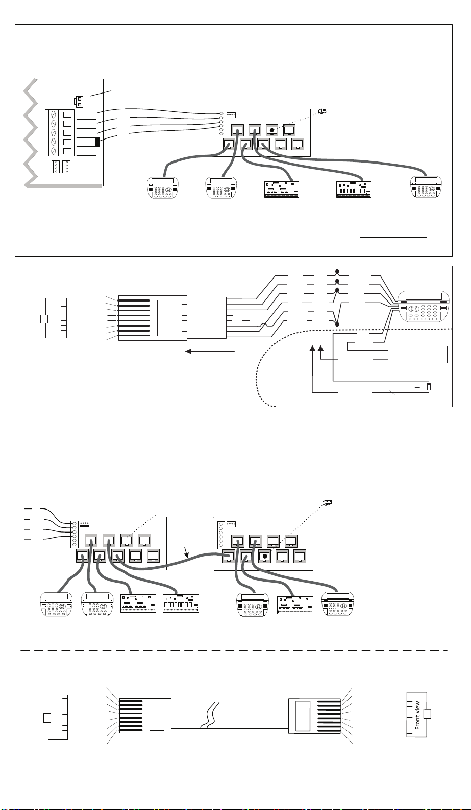
1. Connect the M1DBH to the +12V, Data A, Data B,
and Neg screw terminals on the M1 Control using
a dedicated 4 wire, 22 gauge min. cable.
- An optional ELK-W018B ribbon cable may be used
if the M1DBH is less than 24" from the M1 Board.
2. Run a CAT5/6 (Category 5/6) 4 pair, twisted cable to
each data bus device location.
- Terminate the CAT5/6 cable at the M1DBH location
using a RJ45 plug and the appropriate crimping
tool. Follow the 568A wiring standard. (see color
code on back of page) Note: RJ45 plugs are not
included with the M1DBH due to the variety of
brands and terminating tools available.
- At each device location, attach the CAT5/6 wires to
the devices' screw terminals or ying lead harness
using the 568A standards shown on the ip side.
The Pos & Neg (CAT5/6 Brn/Wht) wires connect
singularly to the Pos & Neg terminations. The data
A & B, plus the data A1 & B1 (CAT5/6 Grn/Wht & Org/
Wht) wires will connect "doubled up" under the
device terminations labeled A and B. This creates a
form of 3-way connection which routes the data A1
& B1 back to the cable's RJ45 plug so the M1DBH
can feed it to the RJ45 receptacle for the next
device. This arrangement places the data lines in
a series or "daisy chain" conguration, critical for
proper operation. Daisy Chaining is important
due to the high speed of the M1's RS-485 data bus.
Refer to STEP 4 for terminating of the daisy chain.
3. Plug each data bus cable into it's own RJ45 jack
on the M1DBH board starting with J1. Do not skip
over empty positions.
4. Insert the included EOL resistor terminating plug in
the unused jack that follows the last data bus cable.
This plug terminates the data bus with a 120 Ohm
resistor across the A & B data return lines coming
from the last wired device.
5. An additional M1DBH Hub may be connected
in a straight (single) daisy chain from the rst by
construction of a CAT5/6 Crossover cable with
RJ45 plugs on each end. See diagram on ip side.
The 2nd M1DBH can be used to increase the total
number of data bus home runs. The crossover
cable must be plugged into the next available
unused port on the rst M1DBH and then to the
rst port (J1) on the next M1DBH.
WARNING: Never aempt to mul-spoke M1DBH's
o one another! They may only be interconnected
in a single daisy chain fashion. Never exceed the
4,000 . max. bus distance. The length of each
CAT5 home run must be calculated as DOUBLE.
Never use any cable other than a good quality
CAT5/6 cable with the M1DBH ports. Never aempt
to splice or extend any of the M1DBH CAT5/6 port
cables with ordinary mul-conductor cable! Elk
Products will not support or approve any deviance
from these instrucons.
WARNING!TheRS485DataBusmustNEVERhavemore
thattwo(2)terminatingresistors(jumpers).Reliabilityand
responsewillbeaffected!
ELK‐M1DBHDataBusHubconnectedtoM1MainControl
J2 J4 J6 J8
J1 J3 J5 J7 J9
InsertRJ45TerminatingPlugin1stunusedjack
andterminatethecontrolatJP3.
DONOTTERMINATEOTHERDEVICES
!
CAT5Cables
NEG‐
DATAB
+12V
DATABUS
+VKP
DATAB
DATAA
NEG
EGND
J1J2
JP3
RS‐485DATABUS
DATAA
M1MainBoard
J10
 
Keypad
 
Keypad
 
Keypad
Spare1
Spare2
+
A
B
‐
MountM1DBHinsidecontrol.
Use4conductorcabletoconnect
totheM1DataBusterminals.
**SEEWARNINGABOVE
NOTE:RS‐485DataBusMax.wirelengthis4000ft.Total.EachCAT5homerunfromtheM1DBHmustbecalculatedasdoublethe
runningdistancesincetheDataA&Blinestraveloutandthenback(A1&B1)wheretheyareusedtofeedthenexthomerun.
TheELK‐M1DBHDataBus Hub isfornew installationswhere it ispossible to run multipleCAT5/6homeruncables.  The RJ45jacks allow neatand
organizedconnections.ThethirdwirepairintheCAT5/6cableisusedtoreturntheDATAlinesbackfromeachdevicewheretheyareusedtofeed
the next adjacent jack.  The result is the M1DBH circuitry daisy chains the devices by series connecting the DATA lines A & B.  Termination is
accomplishedwithaplug‐inRJ45terminator(supplied).
TheCAT5/6CablesmustbecontinuousfromtheM1DBHtotheDeviceterminalsorflyingleadharnessonalltheKeypads.
DONOTMAKEANYINTERMEDIATESPLICESORUSEOTHERCABLES.WestronglyrecommendusingCAT5/6cablewiththe
largestavailablewiregauge.Thelongerthedistancesthemoreimportantitistohavelargergaugewire.
Terminating
Jumper
BLACK
RED
GREEN
WHITE
WerecommendtheM1DBHbemountedinclosephysicalproximitytotheM1
Controlwherepossible.TwoormoreM1DBHboardsmaybeconnectedina
singledaisychainbycloselyfollowingthediagramatbottomofthispage.
Refer to Keypad
Instructions
for more info
about Output
and Zone Input
+
-
A
A1
B
B1
TO CONTROL
8 - Brown
7 - Wht/Brn
6 - Orange
5 - Wht/Blue
4 - Blue
3 - Wht/Org
2 - Green
1 - Wht/Grn
Pin1
RJ45 Plug
Blue pair is
unused
Color Code for CAT5 Data Bus Cables
Pin1
Front
view
Optional programmable Zone Input
Optional programmable Output
-
+
N.C. N.O.
2200
Ohm
EOL
To BLACK (Neg)
To BLACK (Neg)
Wht/Blue
Brown
Wht/Brn
Orange
Wht/Org
Green
Blue Wht/Grn
RED +12V
BLACK (-)
GREEN
WHITE
BROWN
BLUE
Keypad
CAT5
or
CAT6
Cable
To (-) Neg
Black wire
Load (50mA max)
I.E. LED, Relay
DoNOTexceed4,000ft.max.DataBus
distance.ThelengthofeachCAT5
homerunmustbecalculatedasDOUBLE
itsphysicallength.
BLACK
RED
GREEN
WHITE
Proper(allowed)methodforDaisyChainingtwoormoreELK‐M1DBHDataBusHubs
J2 J4 J6 J8
J1 J3 J5 J7 J9
InsertRJ45TerminatingPlugin1stunused
jackandterminatethecontrolatJP3.
DONOTTERMINATEOTHERDEVICES!
CAT5Cables
J10
 
Keypad
 
Keypad
ACrossovercable(diagrambelow)mustbepluggedintothefirstunusedportofthefirstM1DBHtoportJ1onthenextM1DBH.
8‐Brown
7‐Wht/Brn
6‐Orange
5‐Wht/Blue
4‐Blue
3‐Wht/Org
2‐Green
1‐Wht/Grn
Pin1
RJ45Plug
CAT5or
CAT6Cable
Pin1
Frontview
1‐Wht/Org
2‐Orange
3‐Wht/Grn
4‐Blue
5‐Wht/Blue
6‐Green
7‐Wht/Brn
8‐Brown
Pin1
RJ45Plug
Pin1
CROSSOVERCABLE
Orangepair"swaps"position
withGreenpair
J2 J4 J6 J8
J1 J3 J5 J7 J9
J10
 
Keypad
 
Keypad
CAT5
Crossover
Cable
Thedatabusmustappearasasingleseriescircuit,meaningasingledaisychaintypeof
connection.Neverattempttomulti‐spokemultipleM1DBH’soffasingleM1DBH.
NOTerminatingPlughere!
TheCAT5/6CablesmustbecontinuousfromtheM1DBHtotheDeviceterminalsorflyingleadharnessonalltheKeypads.
DONOTMAKEANYINTERMEDIATESPLICESORUSEOTHERCABLES.WestronglyrecommendusingCAT5/6cablewiththelargestavailablewiregauge.The
longerthedistancesthemoreimportantitistohavelargergaugewire.
WARNING: Never use any cable other than a good quality CAT5 cable with the M1DBH ports.
Never attempt to splice or extend any of the M1DBH port cables using ordinary multi-conductor
cable! Elk Products will not support or approve any deviance from these instructions.

Other Elk Products Switch manuals

Elk Products ELK-M1DBHR User manual

Elk Products

Elk Products ELK-M1DBHR User manual

Elk Products ELK-9100 User manual

Elk Products

Elk Products ELK-9100 User manual

Popular Switch manuals by other brands

Borri STS 16A user manual

Borri

Borri STS 16A user manual

Dell PowerConnect PC7024 Technical white paper

Dell

Dell PowerConnect PC7024 Technical white paper

UTEPO UTP7204GE Quick installation guide

UTEPO

UTEPO UTP7204GE Quick installation guide

HPE FlexFabric 5940 SERIES Fundamentals Command Reference

HPE

HPE FlexFabric 5940 SERIES Fundamentals Command Reference

NETGEAR GS724AT - ProSafe Gigabit Smart Switch Hardware installation guide

NETGEAR

NETGEAR GS724AT - ProSafe Gigabit Smart Switch Hardware installation guide

QOLSYS IQ Power Switch-PG installation guide

QOLSYS

QOLSYS IQ Power Switch-PG installation guide

ATEN CS74U user manual

ATEN

ATEN CS74U user manual

Acnodes KVS801 user manual

Acnodes

Acnodes KVS801 user manual

D-Link DMS-107 Quick installation guide

D-Link

D-Link DMS-107 Quick installation guide

Honeywell CENTRAL HUB Quick reference guide

Honeywell

Honeywell CENTRAL HUB Quick reference guide

H3C S6520X-SI Series installation guide

H3C

H3C S6520X-SI Series installation guide

Moxa Technologies EtherDevice EDS-G205A-4PoE-1GSFP Hardware installation guide

Moxa Technologies

Moxa Technologies EtherDevice EDS-G205A-4PoE-1GSFP Hardware installation guide

Alaxala AX6300S series quick start guide

Alaxala

Alaxala AX6300S series quick start guide

Weidmüller IE-SW-SL28M manual

Weidmüller

Weidmüller IE-SW-SL28M manual

Leviton PK-A3419-10-00-5A installation instructions

Leviton

Leviton PK-A3419-10-00-5A installation instructions

Cisco Catalyst 2960-L Hardware installation guide

Cisco

Cisco Catalyst 2960-L Hardware installation guide

Belkin F5U302DNGL user manual

Belkin

Belkin F5U302DNGL user manual

Kramer VS-24x1 user manual

Kramer

Kramer VS-24x1 user manual

manuals.online logo
manuals.online logoBrands
  • About & Mission
  • Contact us
  • Privacy Policy
  • Terms and Conditions

Copyright 2025 Manuals.Online. All Rights Reserved.