manuals.online logo
Brands
  1. Home
  2. •
  3. Brands
  4. •
  5. Aruba Networks
  6. •
  7. Network Router
  8. •
  9. Aruba Networks MSR1200 User manual

Aruba Networks MSR1200 User manual

0511133-02
Aruba Networks
MSR1200 Installation Guide
MSR1200 Installation Guide 2
Copyright 2005-2012 by Aruba Networks, USA. All rights reserved.
Statement of Conditions
In the interest of improving internal design, operation function, and/or reliability, Aruba Networks reserves
the right to make changes to products described in this document without notice. Aruba Networks does not
assume any liability that may occur due to the use or application of the product(s) described herein.
FCC and Industry Canada Statement
This device has been tested and found to comply with the limits for a Class B digital device, pursuant to
part 15 of the FCC Rules and Canadian ICES-003. For products available in the USA and Canada, only
channels 1 through 11 can be used. Do not operate such products on any other channels.
This device complies with Part 15 of the FCC Rules. Operation is subject to the following two conditions:
(1) This device may not cause harmful interference, and (2) This device must accept any interference
received, including interference that may cause undesired operation.
This equipment has been tested and found to comply with the limits for a Class B digital device, pursuant to
part 15 of the FCC Rules. These limits are designed to provide reasonable protection against harmful
interference in a residential installation. This equipment generates, uses, and can radiate radio frequency
energy and, if not installed and used in accordance with the instructions, may cause harmful interference to
radio communications. However, there is no guarantee that interference will not occur in a particular
installation. If this equipment does cause harmful interference to radio or television reception, which can be
determined by turning the equipment off and on, the user is encouraged to try to correct the interference by
one or more of the following measures:
Reorient or relocate the receiving antenna.
Increase the separation between the equipment and receiver.
Connect the equipment into an outlet on a circuit different from that to which the receiver is
connected.
Consult the dealer or an experienced radio/TV technician for help.
RF Radiation Exposure Statement
This equipment complies with FCC RF radiation exposure limits. This equipment should be installed and
operated with a minimum distance of 20 cm between the radiator and your body for 2.4 GHz and 5 GHz
operations. This transmitter must not be co-located or operating in conjunction with any other antenna or
MSR1200 Installation Guide 3
transmitter. When operated in the 5.15 to 5.25 GHz frequency range, this device is restricted to indoor use
to reduce the potential for harmful interference with co-channel Mobile Satellite Systems.
MSR1200 Installation Guide 4
1. Panel
Front Panel LED
The table below lists the meanings of the LEDs on the MSR1200:
Table 1-1 MSR1200 LED Status Indicators
LED
Color
QTY
Definition
Power
Green
1
Displays the power or connection status:
•Dark: No power to the unit
•
Green: Unit has power
RADIO0
Green
1
Displays the Radio 0 link status:
•Dark: Radio 0 is not providing either access (SSID) or backhaul
(mesh) service
•Green: Radio 0 is providing access (SSID) service or backhaul
(mesh) service
RADIO1
Green
1
Displays the Radio 1 link status:
•Dark: Radio 1 is not providing either access (SSID) or backhaul
(mesh) service
•Green: Radio 1 is providing access (SSID) service or backhaul
(mesh) service
E0 10/100 Green 1 Display the Ethernet 0 status:
•Dark: No uplink on the Ethernet port
•
Green: The link speed is 10M or 100M
E0 1000 Green 1 Display the Ethernet 0 status:
•Dark: No uplink on the Ethernet port
•
Green: The link speed is 1000M
Note
Starting with MeshOS 4.5, you can turn off the LEDs in the MSR1200 devices using the WMI and the
CLI. The LEDs are enabled by default. This option may be used to disable the LED lights in a
MSR1200 device to avoid unwanted attention or disturbance. This feature turns off only the LED lights
that indicate the software status, for example the RF. The LEDs that indicate the hardware status, for
example Power, P/S, POE, and ETH, cannot be turned off using this feature. For additional details,
refer to the Aruba MeshOS User Guide and the Aruba MeshOS Command Reference Guide.
MSR1200 Installation Guide 5
Rear Panel Interfaces
a) Power: DC input
b) Ethernet port: 10/100/1000BASE-T (RJ-45), supports POE
c) Reset button: to manually restart MSR1200
d) Default button: to restore MSR1200 to factory setting
e) Console port: to configure MSR1200
2. Installation Flowchart
3. Preparing for Installation
Check the Installation Environment
Before installing MSR1200, check the environment to ensure that the MSR1200 is working in a good
environment. The requirements on the environment include installation, position, power supply,
network, temperature, humidity, radio interference, wind force, dust, and erosion.
Try to avoid obstacles in the coverage environment
MSR1200 Installation Guide 6
Stay away from the electronic devices or equipments that may produce radio frequency noise
(such as microwave oven)
Installation Tools
Installation Tools
General Tools ruler (1m), marker, knife, masonry drill and drill bits
Special Tools stripping pliers, press pliers, crystal head pressure pliers
Auxiliary Tools Ladder, rubber hammer
Note
The tool list above is only for reference. Choose proper tools according to the actual installation
environment.
Unpacking
Before unpacking, make sure the package is undamaged. After unpacking, pay attention to the
following aspects:
If the items in the package box are not the same as the package contents stated, contact the
device supplier.
If the package box is eroded or water-soaked contact the device supplier.
Package Contents
Aruba MSR1200 AirMesh Router
4 x Omni Antennas
USB Console Cable
Installation Guide
Quick Start Guide
4. Power Supply
The MSR1200 supports PoE (Power over Ethernet) or local power supply via the power adaptor.
POE
Connect one end of the twisted pair to the Ethernet interface of the MSR1200 and the other end to the
Out port of the switch or power injector.
Local Power Supply
Connect one end of the power adaptor to the power port of the MSR1200 and the other end to the AC
power plug.
MSR1200 Installation Guide 7
5. Connecting the Ethernet Cable
Connect one end of the Ethernet cable to the Ethernet interface of the MSR1200 and the other end to the
Ethernet interface of the switch.
Note
This requires a shielded Ethernet cable and the switch must be properly grounded.
6. Installing the Antenna
Connect one end of the omni antenna that is shipped with the MSR1200 to the antenna connector. Adjust
the omni antenna to ensure it is in a good direction.
Installing the antenna feeder
If using the antenna feeder, you need to use RP-SMA/M - N/F or RP-SMA/M – N/M convertible cable to
connect the antenna interface (RP-SMA/F) of the MSR1200 and the N-type interface of the antenna feeder
or power splitter.
7. Installing MSR1200 on a Wall
Choose the installation position of the MSR1200 and use a pencil to mark the position of four holes on the
wall. Use four expansion anchors (¢6) and screws (M4X30) to fix the MSR1200 on the wall.
MSR1200 Installation Guide 8
8. Checking the MSR1200 Work Status
To log in to the MSR1200 via the WMI (Web Management Interface), use the settings in the following
table:
Browser
Microsoft Internet Explorer, Mozilla Firefox, or any
other standard browser.
Default IP address
http://192.168.216.1
SSID
ArubaDefault
802.11 mode
802.11a/g/n
Channel
1
Country/Region Code
US
Authentication/Encryption
None
DHCP
Disabled
For additional details, refer to the Aruba MeshOS User Guide.
To log in to the MSR1200 via the console port, use the settings in the following table:
The default username is root and the password is public.
Product SKU
Serial Number
Baud
Rate
Data
Bits
Parity
Stop
Bits
Flow
Control
MSR1K2SN0
MSR1K2SN0-JP
MSR1K2SN0-US
14 characters
(For example: 26A02110500467)
115200 8 None 1 None
MSR1K2
MSR1K2-JP
MSR1K2-US
9 characters
(For example: AZ1234567)
9600
8
None
1
None
The baudrate setting depends on the manufacturing date of the MSR1200 (before or after March 2012) and
the Serial Number (14 characters or 9 characters). All the SKUs for this product along with the
corresponding baudrates are listed in the table above.
MSR1200 Installation Guide 9
9. Specifications
Antenna Connectors 4* RP-SMA connectors
Interfaces 10/100/1000BASE-T (RJ-45)
Console port (USB)
Indicators Power
Ethernet LED
Radio LED
Reset Button Support
Dimensions 260 x 160 x 48 mm (W x L x H)
Weight 1.60 kg
Environmental
Storage temperature: -25 to 85°C
Operating temperature: 0 to 50°C
Non-operating humidity: 5%~95% (non-condensing)
Operating humidity: 10%~95% (non-condensing)
System Memory 128 MB DRAM
2 X16 MB flash
Input Power Requirements DC input: 36V~57V
POE 802.3af
Output range: 36V~57V, 15.4W
Power <10W
MSR1200 Installation Guide 10
10. Contacting Support
Main Site arubanetworks.com
Support Site support.arubanetworks.com
Airheads Social Forums and
Knowledge Base community.arubanetworks.com
North American Telephone 1-800-943-4526 (Toll Free)
1-408-754-1200
International Telephones arubanetworks.com/support-services/aruba-support-
program/contact-support/
Software Licensing Site licensing.arubanetworks.com/login.php
Wireless Security Incident
Response Team (WSIRT) arubanetworks.com/support/wsirt.php
Support Email Addresses
Americas and APAC support@arubanetworks.com
EMEA emea_support@arubanetworks.com
WSIRT Email
Please email details of any
security problem found in an
Aruba product.
wsirt@arubanetworks.com

Other manuals for MSR1200

1

Other Aruba Networks Network Router manuals

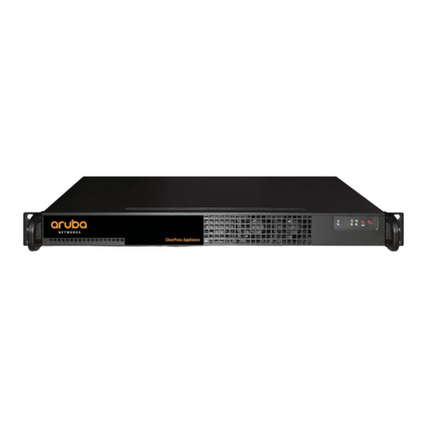
Aruba Networks CLEARPASS APPLIANCE Manual

Aruba Networks

Aruba Networks CLEARPASS APPLIANCE Manual

Aruba Networks MSR1200 User manual

Aruba Networks

Aruba Networks MSR1200 User manual

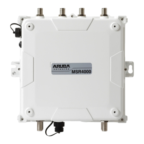
Aruba Networks AirMesh MSR4000 User manual

Aruba Networks

Aruba Networks AirMesh MSR4000 User manual

Aruba Networks MSR2000 User manual

Aruba Networks

Aruba Networks MSR2000 User manual

Popular Network Router manuals by other brands

Billion BiPAC 7402VGO user manual

Billion

Billion BiPAC 7402VGO user manual

elero Centero operating instructions

elero

elero Centero operating instructions

Calix Gigacentre 844g user manual

Calix

Calix Gigacentre 844g user manual

Comnet CNGE20FX4TX16MS Installation and operation

Comnet

Comnet CNGE20FX4TX16MS Installation and operation

Cisco RV042 - Small Business Dual WAN VPN Router datasheet

Cisco

Cisco RV042 - Small Business Dual WAN VPN Router datasheet

Linksys RVS4000 user guide

Linksys

Linksys RVS4000 user guide

HotBrick VPN 800 user guide

HotBrick

HotBrick VPN 800 user guide

D-Link EAGLE PRO AI M15 manual

D-Link

D-Link EAGLE PRO AI M15 manual

Network Everywhere NR041 user guide

Network Everywhere

Network Everywhere NR041 user guide

GRASS VALLEY Profile XP PVS2000 installation guide

GRASS VALLEY

GRASS VALLEY Profile XP PVS2000 installation guide

Maipu MP2900-04-AC installation manual

Maipu

Maipu MP2900-04-AC installation manual

NETGEAR XE102 - Wall-Plugged EN Bridge user guide

NETGEAR

NETGEAR XE102 - Wall-Plugged EN Bridge user guide

Rose Band ShowLED Classic user manual

Rose Band

Rose Band ShowLED Classic user manual

ADTRAN NetVanta 3448 Specifications

ADTRAN

ADTRAN NetVanta 3448 Specifications

Grandstream Networks GWN7001 Quick installation guide

Grandstream Networks

Grandstream Networks GWN7001 Quick installation guide

Shenzhen Hongdian Technologies H8951-LQA user manual

Shenzhen Hongdian Technologies

Shenzhen Hongdian Technologies H8951-LQA user manual

Hawking HWR54G Quick instruction guide

Hawking

Hawking HWR54G Quick instruction guide

Draytek Vigor2925 Series user guide

Draytek

Draytek Vigor2925 Series user guide

manuals.online logo
manuals.online logoBrands
  • About & Mission
  • Contact us
  • Privacy Policy
  • Terms and Conditions

Copyright 2025 Manuals.Online. All Rights Reserved.