ARVOO PICASSO PCI-3C PRO User manual

PICASSOTM PCI-3C(PRO)
Dual input Triple channel Analog Video
PCI frame grabber with optional CVBS inputs
User Manual
Draft version
Rev 2.B doc 1.0

Rev 2.B doc 1.0
Copyright 2001 by ARVOO Engineering BV
All rights reserved. No part of this publication may
be reproduced, stored in a retrieval system, or
transmitted, in any form by means, electronic,
mechanical, by photocopying, recording, or
otherwise, without the prior written permission of
ARVOO Engineering BV.
Information furnished by ARVOO Engineering BV
is believed to be accurate and reliable; however, no
responsibility is assumed by ARVOO Engineering
BV for its use; nor for any infringements of patents
or other rights of third parties which may result from
its use. No license is granted by implication or
otherwise under any patent rights of ARVOO
Engineering BV.
picassoTM is a trademark of ARVOO Benelux BV.
PentiumTM is a registered trademark of the Intel
Corporation.
ARVOO Engineering BV
P.O. Box 439
3440 AK Woerden
The Netherlands
url: www.arvoo.nl
e-mail: [email protected]

CONTENTS
picassoTM PCI-3C User Manual
- 3-
CONTENTS
OVERVIEW................................................................................................................................................... 4
FEATURES .................................................................................................................................................... 5
1. GETTING STARTED........................................................................................................................... 6
1.1 HARDWARE REQUIREMENTS ................................................................................................................ 6
1.2 INSTALLING THE PICASSOTM ................................................................................................................. 6
1.3 I/O CONNECTORS................................................................................................................................. 7
1.3.1 Video sources ............................................................................................................................ 7
1.3.2 General Purpose Input /Output connector.................................................................................. 9
APPENDIX A ................................................................................................................................................11

OVERVIEW
OVERVIEW
The picassoTM PCI-3C is a high-performance ‘plug and play’ PC-card for the PCI-bus. It enables
each standard PCI system to capture and store single images for image processing or full-frame
display of real-time video in a window (30 frames/sec).
The picassoTM PCI-3C operates as a PCI bus master, allowing it to transfer images directly to
the system or VGA memory without impacting the processor.
The picassoTM PCI-3C has two analog RGB inputs with separate sync inputs. Sync is also
accepted on one of the color inputs. The video input is software controlled and accepts both
standard and non-standard video signals. Progressive scan and line scan video formats are
optionally supported. The grabber is also designed as a triple channel 8-bit digitizer for
monochrome video (three synchronized B&W cameras).
The picassoTM PCI-3Cpro supports additional acquisition from CVBS video signals.
The 3Cpro CVBS inputs are software controlled and accept NTSC and PAL video formats.

FEATURES
picassoTM PCI-3C User Manual
- 5-
FEATURES
n32-bit PCI interface, 3.3V or 5V I/O compatible
The picassoTM is a full PCI 2.1 bus master with a transfer rate up to 132
Mbytes/sec. This allows the bus master to transfer up to 30 frames/sec. Support
of zero wait state burst transfers.
nTwo RGB colour/multiple monochrome video inputs
Several configurations are possible, selected by software. Two RGB cameras,
one active. Two pairs of 3 synchronised monochrome video inputs. The
picassoTM PCI-3Cpro supports four additional CVBS (composite colour) video
inputs or two S-Video inputs.
nResolution
24 bit color levels. Standard square pixel format with 768/640 active pixels
resolution per frame. NTSC, PAL, SECAM, interlaced or progressive scan.
The maximum sample frequency is 20MHz.
nRS-170 CCIR 601 level-compatible
nSquare pixel – 1:1 aspect ratio
nMemory
Memory Management Unit (MMU) supports Virtual Memory up to 4
Mbytes/DMA channel.
nData Formats
RGB digital Video can be stored in several formats (RGB565, RGBα555,
RGB55α5, RGB24) in system memory or the displays adapter frame buffer.
CVBS digital video can be stored as RGB32, RGB24, RGB15, RGB8, YUV444,
YUV422, YUV411, YUV8 and YUV8-GRAY
nTwo digital inputs and two digital outputs
The picassoTM has two optical isolated digital inputs and outputs. They are
software controlled and they can be used for external events such as light
switching and camera triggering. The inputs can be programmed as interrupt for
fast input reaction time.

GETTING STARTED
picassoTM PCI-3C User Manual
- 6-
1. GETTING STARTED
1.1 Hardware Requirements
The following minimum system characteristics are required by the picassoTM .
nIBM PC or compatible with Pentium 266MHz (or better).
nOne available PCI version 2.1 bus master expansion slot (32-bits, 3.3V or 5V I/O).
n32 Mbytes of DRAM.
nA mouse or compatible pointing device.
nOne 3.5 inch floppy disk drive for installation.
ARVOO recommends only motherboards that are equiped with modern PCI-chipsets, good test
results have been found with e.g. the Intel 440BX, i810, i815 or i820 chipsets.
1.2 Installing the picassoTM
1. Select a 32-bit PCI bus master expansion slot. Refer to your computer systems user manual to
determine which slots are bus masters.
2. Remove the metal bracket.
3. Before handling the board, discharge any static build up on your body by touching the metal
case of the computer. Remove the board from its bag and hold the picassoTM by its top edges
and do not touch its components.
4. When the bottom of the board contacts the bus connector, gently press down on the board
until it is fully seated. Secure the board using the removed screw from the slot cover.
5. Connection of the video signal to the picassoTM is accomplished using a standard VGA-
connector (15 pins SUB-D).

GETTING STARTED
picassoTM PCI-3C User Manual
- 7-
1.3 I/O connectors
Figure 1
1.3.1 Video sources
The picassoTM PCI-3C supports two RGB video sources or six B&W. The picassoTM PCI-3Cpro
supports two RGB, six B&W, or four CVBS (composite colour) video sources. The selection of
the different video inputs is software controlled.
The green LED (D1) [see Figure 1] indicates locking of the frame grabber on an incoming video
signal.
When the green LED is flashing it indicates an error condition:
-Video input signal doesn’t contain sync timing.
-Wrong selection of video standard (PAL instead of NTSC).
-Wrong selection of sync input (sync on red instead of sync on green)
When the green LED doesn’t light-up at all, it indicates:
-No video or sync signal.
-Wrong video input-port selected (Y2 instead of Y1).
The green LED doesn’t indicate lock information when you capture CVBS video signals with
the picassoTM PCI-3Cpro.You can display or capture one camera at a time.
GETTING STARTED
picassoTM PCI-3C User Manual
- 8-
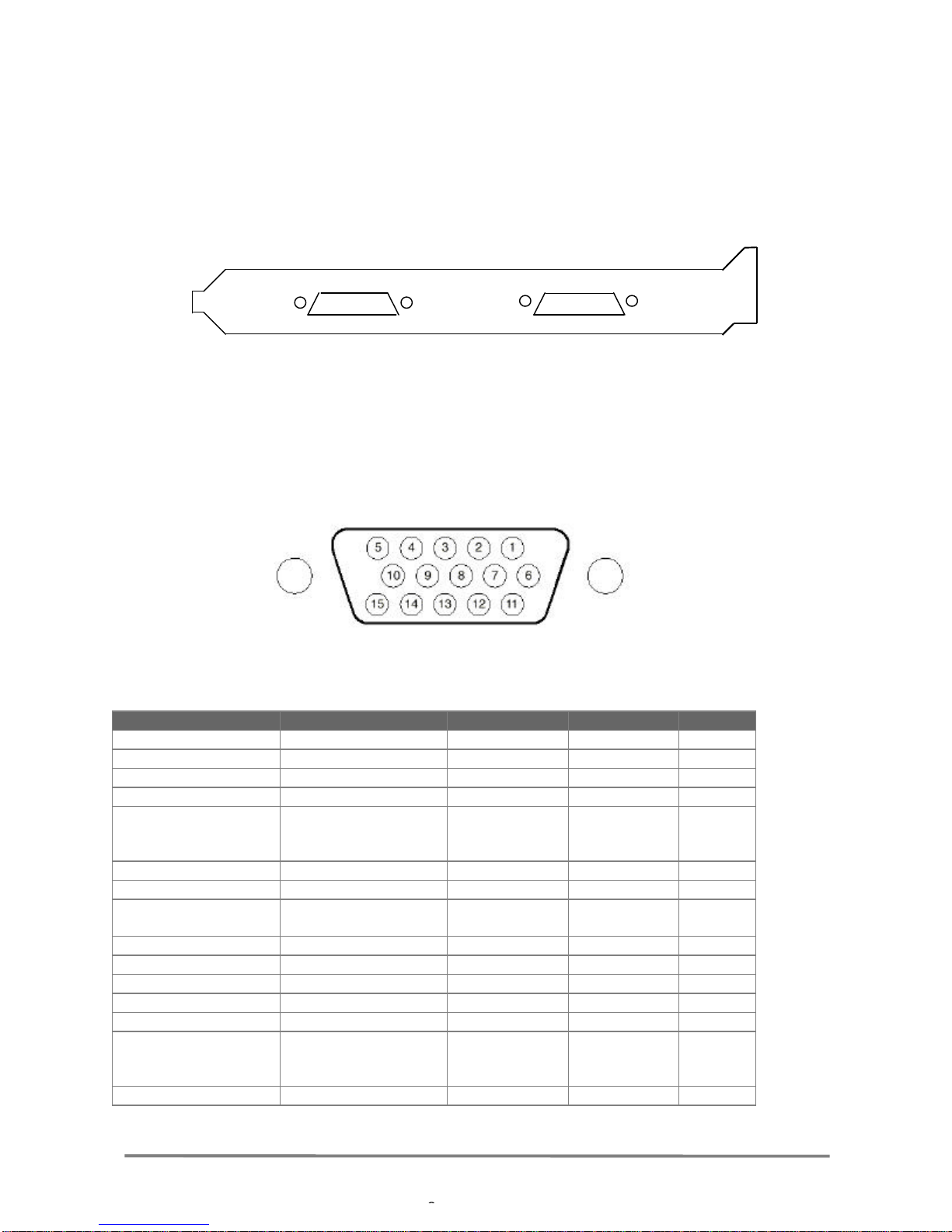
The video input-connector is a SUB-D15 connector and the GPIO is a SUB-D9 connector [see
Figure 2].
Table 1shows connection of the video sources to the SUB-D15 connector. The pin assignment
depends on the video sources that are used. Four modes can be distinguished: (1) RGB mode for
3 component video, e.g. RGB or YUV. (2) Y-mode for B&W video. (3) CVBS-mode for CVBS
composite video. (4) S-video-mode for S-video (Y/C) video.
SUB-D15 SUB-D9
Figure 2: Close-up of RGB-VID and GPIO connectors.
Figure 3: Close-up of the SUB-D15 female connector
RGB-mode Y-mode CVBS-mode S-video Pins
R1 Y1 NOT USED NOT USED 1
G1 Y2 NOT USED NOT USED 2
B1 Y3 NOT USED NOT USED 3
GND GND GND GND 4
Composite sync input
for camera 1
(ana1og or TTL level)
Composite sync input
for Y1,Y2 or Y3
(ana1og or TTL level)
NOT USED NOT USED 5
GND GND GND GND 6
NC NC NC NC 7
Composite sync output /
External sync input Composite sync output /
External sync input NOT USED NOT USED 8
NC NC NC NC 9
GND GND GND GND 10
R2 Y4 C1 input Y1 11
G2 Y5 C2 input Y2 12
B2 Y6 C3 input C1 13
Composite sync input
for camera 2
(ana1og or TTL level)
Composite sync input
for Y4,Y5 or Y6
(ana1og or TTL level)
C4 input C2 14
GND GND GND GND 15
Table 1SUB-D15

GETTING STARTED
picassoTM PCI-3C User Manual
- 9-
The Composite SYNC OUT pin is TTL compatible and re-outputs the Composite SYNC IN
(also when SYNC on component [green, red or blue] is selected) and can be used for camera
synchronisation.
1.3.2 General Purpose Input /Output connector
The General Purpose Inputs and Outputs are connected to the picassoTM by a SUB-D9 female
connector. In Figure 4 you see a drawing of the SUB-D9 connector. The pin connections are
listed in Table 2.
When you use the general-purpose inputs or outputs you have to connect an external 5V power
supply. The maximum voltage is 5.5V and the input current is 10mA.
When U19 and F1 is placed [see Figure 1] no external power supply is needed. U19 will provide
the external 5V.
F1 is a fuse with the following specifications: 250mA, fast. Ask ARVOO support for more
information.
ATTENTION: The maximum output current is 100mA.
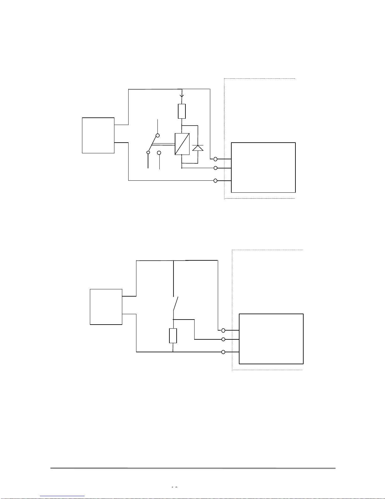
The outputs are open drain, which means that logic 1 will force the output to ground. A wiring
example to connect an output is given below.
ATTENTION: When the computer is turned off and the external power supply stays up the
output will also be forced to ground.
1
5
6
9
Figure 4: Close-up of the
sub D-9 connector
Sub D-9 Pins
Input 0 1
Input 1 2
Output 0 4
Output 1 5
VCC (5V) 6
GND 3,9
Table 2:
GETTING STARTED
picassoTM PCI-3C User Manual
- 10 -
In Figure 6 a wiring example for an output is given.
In Figure 6a wiring example for an input is given.
External 5V
External
power
supply
GND
picassoTM
PC
Input 0/1
Figure 6
output 0/1
External 5V
Imax 100
External
power
supply
GND
picassoTM
PC
Figure 5

APPENDIX A
picassoTM PCI-3C User Manual
- 11 -
Appendix A
1. Electrical specifications
Electrically-compatible with PCI specification, version 2.1.
2. Mechanical specifications
nMechanically compatible with PCI specification, version 2.1, short board.
nMeasures 106x175 mm
nRequires 1 PCI slot
Power requirements Min. Typical Max.
Supply voltage, Vcc 4.75 V 5.0 V 5.25 V
Supply current, Vcc = 5.0 V 1.0 A 1,1 A
Supply voltage, 12Vcc 11.5 V 12 V 12.5 V
Supply current, 12Vcc 110 mA 125 mA
Supply voltage, -12Vcc -11.5 V -12 V -12.5 V
Supply current, -12Vcc 50 mA 75 mA
General purpose voltage 4.5 V 5.0 V 5.5 V
Input current, Vgp = 5.0 V -10 mA -
Output current, Vgp = 5.0 V -80 mA 100 mA
Vi(p-p), CVBS input signal 0.5 V 1.0 V 1.38 V
|Zi|, input impedance 75Ω
Table 3
Environmental
Operating temperature 0º to 70º Celsius
Storage temperature -40º to 85º Celsius
Non-Condensing relative humidity Less than 90%
Table 4
Table of contents


