ASA Electronics AOC-75 User manual

Observation System
AOS58
AOC-75 Features
-High resolution, 1/3” CCD Camera
-Compact/Lightweight Aluminum Die
Cast Body
-Waterproof Housing
-Waterproof Microphone
-Waterproof Normal/Mirror Image
Switch
-Optional Wind deflector
AOM-58 Features
-5” Monochrome Monitor
-Dual camera Input
-Brightness/Contrast/Day-Night Controls
-Volume Control for Internal/External
Speaker
-Power/Stand By Button
-Back-lit Front Panel Controls
OCA-80 Features
-20 Meter Cable with Waterproof
Connections
-Oil, Gas and Grease Resistant
-UV Stable
Operation
Manual
BA

AOS-58
IMPORTANT:
The Voyager Observation system (AOS58) has been designed to provide
years of trouble free operation. Please read this manual thoroughly. This
manual contains instructions to ease the installation of the camera and
monitor. The Voyager Observation system is a supplement to the
standard rear view mirror systems, and will provide additional rear view
vision when installed and maintained properly. The Voyager observation
System is not intended to in any way be a substitute for careful, cautious,
defensive driving or for the consistent adherence to all applicable traffic
laws and motor safety regulations. This product is not intended to be a
substitute for rear view mirrors, or for any other motor vehicle, or boat
equipment mandated by law.
FEATURES:
AOC-75 CCD Camera
-270,000 pixel image sensor
-0.1 Lux sensitivity
-Automatic electronic iris provides a clearer, more consistent image in
low and bright light
-Wide angle lens provides a broad viewing area
-Compact design and light weight simplify installation in most vehicles,
including large boats
-Durable, waterproof construction
-Built-in Microphone for audio pick-up
-Normal /Mirror switch on back of camera
-Wind Deflector reduces build up of dirt on lens
-Waterproof cable connector
AOM-58 Monochrome 5” Monitor
-Day/Night switch
-Brightness and contrast controls
-Volume control
-Illuminated front panel
-Internal speaker with external speaker jack
Contents of one Complete Package:
AOC-75 Camera
Qty.
1Camera
1Camera Bracket
4Attachment Screws with Washers (M4 x 25)
1Wind Deflector
1

4Use without Wind Deflector Screws (#8-32 UNC x 7.5)
4Use with Wind Deflector Screws (#8-32 UNC x 9.0)
AOM-58 Monochrome Monitor
Qty.
15” Monitor
1Snap-On Sun Visor
1Monitor Bracket
1Power Harness with locking connector
1Range marker
4Thumb screws (M5 x 15) with plain washer and spring washers
4Attachment screws with washers (M5 x 12)
OCA-80 Cable
Qty.
120 meter cable with waterproof connector. Oil, gas, and grease
resistant. UV stable
Documents
1Operators manual
BEFORE INSTALLATION:
1. To prevent electrical shock, DO NOT OPEN THE MONITOR CASE. There
are potentially lethal voltages, inside the monitor. There are no user
serviceable parts inside. If evidence of tampering is detected, the
Warranty will be considered void.
2. Keep the monitor away from leaking water, rain, moisture, etc. It is not
waterproofed. Any moisture inside the monitor could cause extensive
damage.
3. Use the thumbscrews to mount the monitor to the bracket.
**CAUTION**
1. Do not open the camera case. This will break the camera’s waterproof
seal. If evidence of tampering is detected, the warranty will be
considered void.
2. Do not mount the camera near the lower area of the vehicle (e.g.
bumper). This reduces the view of camera and may cause physical
damage to the camera.
INSTALLATION INSTRUCTIONS
AOC-75 CAMERA
1. Attach camera bracket (See Figure 1) to upper portion of vehicle.
Attachment point must be sturdy enough to support camera and
bracket.
2

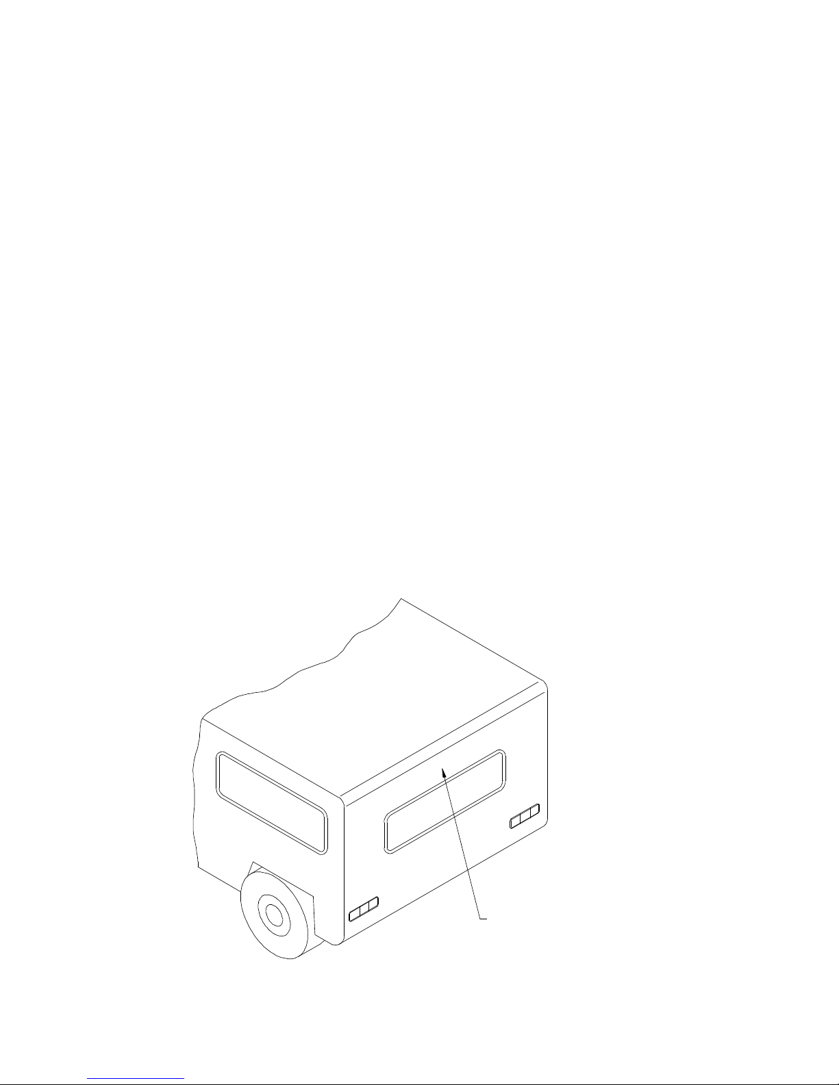
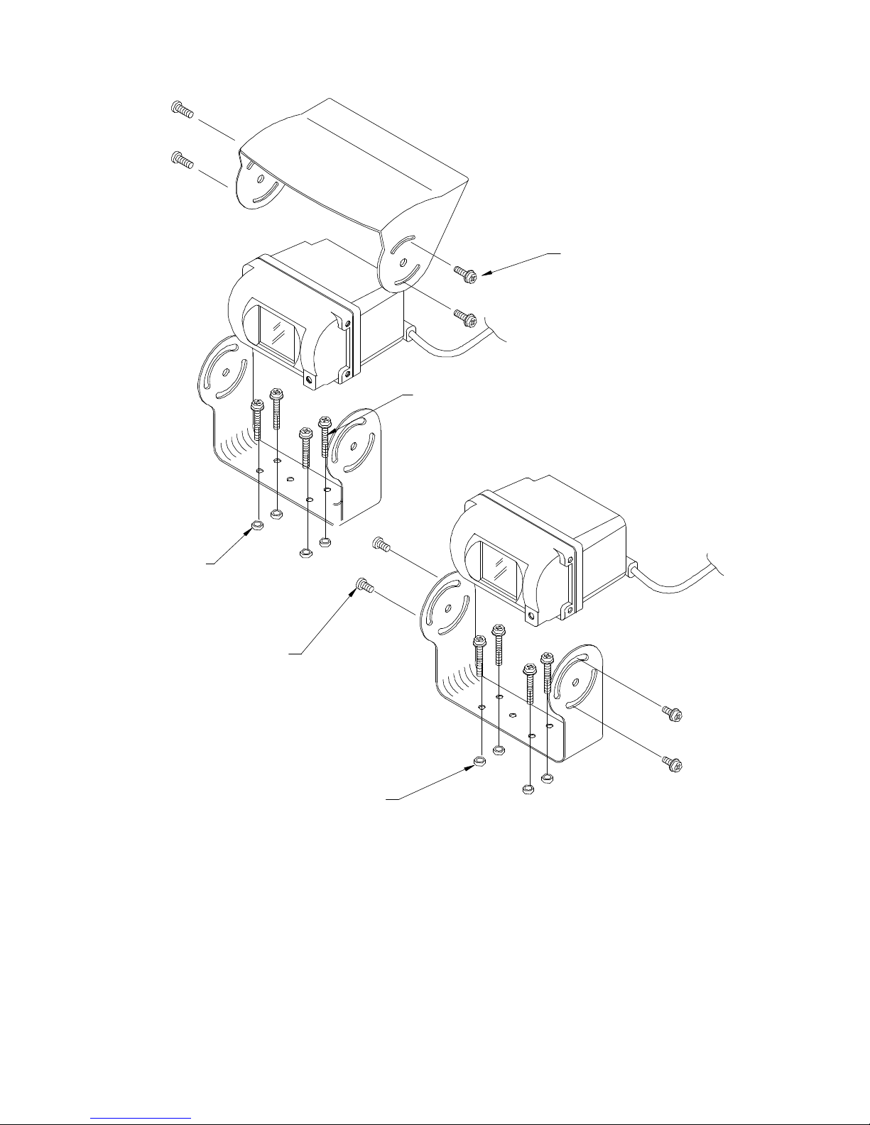
2. Attach camera to bracket using 8-32 UNC screws provided. Adjust
angle as indicated in Figure 2. Use rear or end of bumper as
reference point.
3. Wind deflector may be installed. This deflector is designed to reduce
the build-up of dust, dirt and moisture on the camera lens. (See Figure
3).
AOM-58 MONITOR
1. Attach monitor inside vehicle in a location convenient to the driver
(e.g. center of dash, overhead, or in dash).
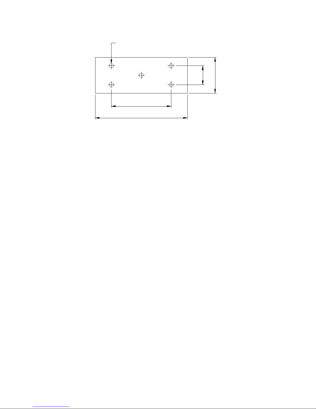
2. Use a compression plate to attach the monitor bracket to the dash or
overhead. (See Figure 4)
3. Adjust mounting angle of the monitor to allow driver to easily view the
screen from all seat positions. (See Figure 5)
4. If necessary, snap sun visor into groove on front face of monitor. Press
all (4) sides of the visor to snap it into place
OCA-80 CABLE
1. The camera-to-cable connection is waterproof. The cable-to-monitor
connection is not waterproof. Be sure to orient the cable properly.
The cylindrical end attaches to the camera. The rectangular box end
attaches to the monitor. (See Figure 6)
2. Do not run the OCA80 cable over sharp edges or camera. Do not
kink the cable. Keep the cable away from hot or rotating parts.
3. Place all excess cable in convoluted tubing.
4. Wire tie the cable securely.
MAINTENANCE
Remove dust and dirt with a damp soft cloth. Heavier dirt should be
removed with a soft cloth and mild detergent. Do not use strong cleaning
agents containing gasoline, benzene, or alcohol. These substances may
damage the exterior surface of the monitor.
**CAUTION**
1. Before drilling, be sure no cable or wiring is on the other side. Be sure to
drill a 19mm/3/4” diameter hole only.
2. Feed as much cable as possible into the vehicle and clamp securely.
This reduces the possibility of being hooked during operation of the
vehicle.
3. Keep all cables away from HOT, ROTATING and ELECTRICALLY NOISY
components.

4. To increase protection of cable, place all excess wire and extension
cable in convoluted tubing.
5. Do not twist camera cable, do not cut pigtail, or cable.
WIRING CAMERA AND MONITOR
1. See wiring diagram for connections to ignition, ground, and backup
circuit. (See Figure 6)
2. Wiring camera:
Drill a 19mm /3/4” diameter hole into the vehicle body near the
camera and bracket.
Connect camera connector to extension cable in vehicle.
Push extra cable into vehicle, (be careful not to kink cable) and fit
grommet into the hole.
Apply sealant around grommet to increase resistance to water
penetration.
3. Wiring monitor:
Insert extension cable into the camera #1 position if (2) cameras
are used, be sure to mark each extension cable properly and plug
second camera into cable #2 position.
Bundle excess cable together using a cable tie or vinyl tape. This
will avoid possible damage to cable during operation.
4. The red wire marked ACC is connected to an ignition power source,
the black wire marked GND is connected to chassis ground, and the
blue wire marked BACK is connected to the vehicle’s back up circuit.
FUNCTIONS AND OPERATION
Monitor: See page 12.
1. Power Switch: STD. BY- Monitor operates when vehicle transmission is
switched into “reverse”.
On- Monitor and system operate when ignition switch is
“ON”
2. Input Switch: “A” used mainly for rear mounted camera or as
specified
by the installer.
“B” used mainly for side mounted camera or as
specified
by the installer.
3. Day/Night Switch: Pre-set brightness and contrast levels optimized for
day
and night operation.
4. Contrast: Variable control or contrast. Should be adjusted if the
3

“Day/Night” switch does not achieve the most
desirable
picture.
5. Brightness: Variable control of brightness. Should be adjusted if
the
“Day/Night” switch does not achieve the most
desirable
picture.
6. Volume: Variable control of internal speaker and external
speaker
volume.
REAR OF MONITOR: See page 12.
1. Power Connection: PIN 1 not used
PIN 2 Ground- Black wire
PIN 3 Reverse circuit- Blue wire
PIN 4 not used
PIN 5 battery back-up- Yellow wire
PIN 6 +12VDC ignition- Red wire
2. Camera A input: Connection to camera extension cable
3. Camera B input: Connection to additional camera
extension
cable
4. External speaker connection: Center pin is positive audio output, used
to
disable the internal speaker and remotely
mount a speaker for driver convenience.
CAMERA CONTROLS AND COMPONENTS
Camera: See page 13
1. Microphone- Waterproof microphone for audio pick up
2. Mirror/Normal Switch- Waterproof switch, to change camera image
from a mirror view (rear of vehicle mounted), to normal view (side or
front mounted camera). See Figure 7.
AFFIXING DISTANCE MARKERS TO THE MONITOR SCREEN
1. Clean monitor screen surface of fingerprints. Set the camera into the
“DOWN” position. Place the distance indicators behind the vehicle at
3 feet, 6 feet, and 9 feet from the back of the vehicle. (See Figure 8)
2. Attach the markers to the monitor screen over the images of the
distance indicators. These markers represent a distance of 3 feet, 6
feet, and 9 feet from the back of the vehicle. (See Figure 8)
4

3. Affix the “STOP” marker on the monitor screen over the image of the
rear view bumper to locate the rear bumper.
4. The monitor screen is now “calibrated” for distances behind the
vehicle of 3 feet, 6 feet and 9 feet.
5
High-Mounted, Centered
Camera Assembly Location
Camera Assembly
Location, High-
Mounted
Centered

Camera Mounting Hole Pattern
Figure 1
6
5-0.165 Dia. Holes
2.601
1.401
1.010
.534

Approximately 80° Field of View
Back of Vehicle, View at
Monitor Screen
Figure 2
7
80°

Figure 3
8
Without Wind Deflector
Screw for use
w/Wind deflector
#8-32 x 3/8"
#8-32 x 5/16"
Screw for use
Included Wind Deflector- Optional Installation
4mm x .7mm
Phillips Hex Head Screw w/Washers
4mm x .7mm x 25.4mm
4mm x .7mm x 25.4mm
Phillips Hex Head Screw w/Washers
4mm x .7mm Hex Nuts
Hex Nuts

Steel Plate Reinforcement (Recommended for Secure Mounting)
Figure 4
9
Plain Washer
Spring Washer
Dashboard or Overhead

Monitor Mounting Hole Pattern
Figure 5
10
20°
20°
5.275
6.240
2.250
2.677
110.0°
5-0.236 Dia. Holes

Figure 6
11
EMI FERRITE CORE
REAR OF MONITOR
(FEMALE BULLET DISCONNECT)
18 TEW BLK (Ground)
18 TEW BLU (Reverse Trigger)
18 TEW RED (12V)
TO MONITOR
CAMERA "A" INPUT
TO MONITOR
20 METERS
WIND DEFLECTOR- OPTIONAL INSTALLATION
WATERPROOF CAMERA CONNECTION
GROMMET TO SEAL THROUGH VEHICLE INTERIOR
18 TEW YEL (Battery)
(MALE BULLET DISCONNECT)
(STRIPPED AND TINNED)
(STRIPED AND TINNED)
3A
1A

MONITOR FRONT VIEW
MONITOR REAR VIEW
Monitor Operating Controls and Connections
12
4 3 2 1
61 2 43 5
AB

Camera Features
13
"NORMAL" SWITCH
MIRROR/
MICROPHONE

MARKER’S EXAMPLE
Figure 8
14
6 FT.
3 FT.
WIDTH OF VEHICLE
INDICATOR
9 FT.

SPECIFICATIONS:
AOS58
System,
1
Camera
Rated Voltage
Operating Voltage
Current Consumption
12VDC, Negative Ground
11 to 30 VDC
1.5 Amperes
AOC75
Camera Sensitivity
Signal System
Image sensor
Viewing Angle
(approx.)
Outer Dimensions
Weight
0.1Lux
NTSC
1/3” B/W CCD w/electronic auto-iris
270K picture elements
110° (H), 80° (V)
2.44” (W) x 1.50” (H) x 1.96” (D)
6.20cm (W) x 3.81cm (H) x 4.98cm
(D)
0.8 lbs.
0.36 Kg.
DISCLAIMER: The use of the VOYAGER observation does not guarantee or
promise that the user will not be in an accident or otherwise not collide
with an object. The VOYAGER Observation System is not intended in any
way to be a substitute for careful and cautious driving, or for the
consistent adherence to all applicable traffic laws and motor safety
regulations. This product is not intended to be a substitute for rear view
mirrors, or for any other motor vehicle or boat equipment mandated by
law.

15

Optional Product List: Televisions
AVT-988 9” Color Television with Remote (12V) AVT988
AVT-1498 13” Color Television with Remote (12V) AVT1498
VCP and DVD Player’s
For use with TV’s and LCD
AVP-7000 Video Cassette Player (12V) AVP7000
AVP-7285 Video Cassette Player (12V) AVP7285
Single Disc DVD Player DVD2101
Headphones
Headphones with Pivoting Earcups HP175
Headphones with Volume Control on Cord HP275
Studio Quality Headphones HP375
Miscellaneous
Remote Controls Please
Call
Wallmount Family Radio Service with 4 Handsets FRS4WM
Replacement Handsets FRS100Y
12V Corded Vacuum VAC21
Rechargeable Flashlight AVF1
Window Mount TV Antenna AN350
B4-Amp Adapter for use with AVT988 9” and AVT1498 13”
TV’s 0891412
2-Amp Adapter for use with AVP7000/7285 Video Cassette
Players 0891436
Wallmount Radios
AM/FM Wallmount Manual Tune w/Cassette Player AWM710
AM/FM Wallmount Electronic Tune w/Cassette Player AWM820
AM/FM Wallmount Stereo w/CD Player AWM930
Marine
AM/FM Stereo w/CD Player MS1000
AM/FM Weatherband Stereo w/Cassette Player MS407
AM/FM Stereo w/Cassette Player (analog tune) MS306
AM/FM Stereo w/Cassette Player (analog tune) MS220
Weatherproof Housing MRH211
50 Watt 6 ½” Speakers (white/black) AMS6
30 Watt 5” Speakers (white/black) AMS5
30 Watt 4” Speakers AMS4
Marine Radio Antenna AN125
To order any of these products, please call 800-688-3135

Or visit our website at www.asaelectronics.com
16
INSTALLATION NOTES:
________________________________________________________________________
________________________________________________________________________
________________________________________________________________________
________________________________________________________________________
________________________________________________________________________
________________________________________________________________________
________________________________________________________________________
________________________________________________________________________
________________________________________________________________________
________________________________________________________________________
________________________________________________________________________
________________________________________________________________________
________________________________________________________________________
________________________________________________________________________
________________________________________________________________________
________________________________________________________________________
________________________________________________________________________
________________________________________________________________________
________________________________________________________________________
________________________________________________________________________
________________________________________________________________________
________________________________________________________________________
________________________________________________________________________
________________________________________________________________________
________________________________________________________________________
________________________________________________________________________
________________________________________________________________________
________________________________________________________________________
________________________________________________________________________
________________________________________________________________________
________________________________________________________________________
________________________________________________________________________
________________________________________________________________________
________________________________________________________________________
________________________________________________________________________
________________________________________________________________________
________________________________________________________________________
________________________________________________________________________
This manual suits for next models
1
Table of contents
Other ASA Electronics Automobile Accessories manuals

ASA Electronics
ASA Electronics Voyager AOS-33 User manual

ASA Electronics
ASA Electronics Voyager VCCS150B User manual

ASA Electronics
ASA Electronics Voyager VCCT130 User manual

ASA Electronics
ASA Electronics oyage AOM703 User manual

ASA Electronics
ASA Electronics Voyager VOM78T User manual

ASA Electronics
ASA Electronics Voyager VCCS130HP User manual

ASA Electronics
ASA Electronics Voyager VCCS150 User manual