ASC Signal NGC-ODU-208-3 User manual

7580368_Rev D Page 0of 89
NGC-ODU
Antenna Controller
Unit
&
Handheld Controller
Advanced Technical Manual
Manual# 7580368 – Revision D
ASC Signal Corporation
CANADA: USA:
606 Beech Street 1120 Jupiter Rd.
Whitby, Ontario, Canada Ste. 102
L1N7T8 Plano,TX75074

7580368_Rev D Page 1of 89
© 2010 ASC Signal Corporation
All Rights Reserved. No part of this document may be photocopied, reproduced, stored in a retrieval system, or
transmitted, in any form or by any means whether electronic, mechanical, or otherwise without the prior written
permission of ASC Signal Corporation.
ASC Signal Corporation reserves the right to change details in this publication without notice.
Trademark Notices
Any and all products and companies named herein are the trademarks of their respective creators and/or
owners.
Open Source Software Notice
This product makes extensive use of Open Source Software (OSS), including but not limited to the operating
system, network agents, user interface shells, and tools used to develop the software. This software gives you,
the customer, the benefit of a large base of well-tested and feature-rich system software while lowering the
expense of providing these features to you. It also carries certain obligations.
Some of this software is licensed by the GNU Lesser General Public License (LGPL), which requires that
modifications be kept public but does not require proprietary source code linked to LGPL'ed libraries be made
public. None of this code has been modified for use in this product.
If you have any questions about our interpretation of our obligations under OSS licenses, do not hesitate to
contact us. Our intent is to comply fully with all licensing obligations.
©ASC Signal Corporation
www.ascsignal.com

7580368_Rev D Page 2of 89
TABLE OF CONTENTS
INTRODUCTION: How to Use This Manual 5
I.I Purpose, Overview, & Description 5
I.II Personnel Requirements 6
I.III Miscellaneous Notices 6
I.IV Warning Symbols 6
I.V Safety Terms Summary 7
I.VI Summary of Safety Precautions 7
I.VII THINGS TO NEVER DO 8
I.VIII Parts Verification 8
1.0 Operation of Handheld Controller 9
1.1 Handheld-to-ODU Connection 10
1.2 Handheld Keypad Breakdown 11
1.3 Handheld Screens Breakdown 12
2.0 ODU System & Parts Overview 29
2.1 ODU with Parts Numbered 29
2.2 ODU Connectors & Cable Glands 30
2.3 A1 Master Controller (MC-7) 31
2.4 A2/A4/(OPTION) A6 Axis Control Units (ACU) 34
2.5 A3/A5/(OPTION) A7 Axis Sending Units (ASU) 36
2.6 A8/A9 El/Az VFD 39
2.7 A10 Power Supply Board 42
2.8 Miscellaneous Parts Descriptions 43
2.9 Terminal Blocks (TB1-TB4) 44
2.10 A13 External Wiring Interface (EWI)-1 45
2.11 A13 External Wiring Interface (EWI)-2 47
3.0 ODU System & Parts Troubleshooting 50
3.1 Antenna JOG/Movement Issues 50
3.2 Directional/Axis Issues 53
3.3 Movement & Wiring Troubleshooting Scenarios/Solutions 56
3.4 Polarization Troubleshooting Issues 56
3.5 Other Pol Troubleshooting Scenarios/Solutions 57
3.6 Other Troubleshooting Scenarios 58
4.0 Cleaning, Inspections, & Maintenance 59
4.1 General Cleaning 59
4.2 Inspections 60
4.3 Preservation of Component Parts (Aluminum Only) 60
4.4 Presence of Moisture/Water 61
5.0 NGC-ODU Spare Kits 62
5.1 VFDs 62
5.2 Power Supplies 62
5.3 Boards 62
5.4 Pol Drive Related 62
5.5 Low Temp Related 62
5.6 Circuit Breakers 63
5.7 Spare E-Stop 63
5.8 Spare Handheld Terminal 63
APPENDIX A: PWA Display Codes & NGC-ODU Faults Glossary 64
APPENDIX B: Theory of Operation 67
APPENDIX C: Glossary Tables 73
APPENDIX D: Equipment Issues & Tech Support 89
LIST OF FIGURES
Figure 1-1: Handheld Controller with Connection Cable 9
Figure 1-2: Handheld Keypad 11
Figure 1-3: Handheld Controller Menu/Screen Tree 12

7580368_Rev D Page 3of 89
Figure 1-4a: Home Screen 13
Figure 1-4b: Button Ribbon Options, HOME SCREEN 2 13
Figure 1-4c: Button Ribbon Options, HOME SCREEN 3 13
Figure 1-5: Jog Screen 14
Figure 1-6: GoTo Screen 15
Figure 1-7a: Parameters Screen 16
Figure 1-7b: Parameters Screen (Edit Mode) 17
Figure 1-7c: Button Ribbon Options, Parameters Edit Mode 2 17
Figure 1-8a: Current Faults 18
Figure 1-8b: Button Ribbon Options, Current Faults 2 18
Figure 1-9: Message Log 19
Figure 1-10: Installation Screen 20
Figure 1-11: Diagnostic Commands Screen 21
Figure 1-12a: Password Screen 22
Figure 1-12b: Button Ribbon Options, Password Screen 2 22
Figure 1-12c: Button Ribbon Options, Password Screen 3 22
Figure 1-13: Edit Fraction Screen 23
Figure 1-14a: Search Screen 24
Figure 1-14b: Button Ribbon Options, Search Screen 2 24
Figure 1-14c: Search Screen with Open Dropdown Menu 25
Figure 1-14d: Search Screen with Item Selected 25
Figure 1-15: Voltage Monitor Mask (bitmask edit screen) 27
Figure 1-16: Shortcuts Screen 28
Figure 2-1: NGC Outdoor Unit 29
Figure 2-2: ODU Interface Connectors & Cable Glands 30
Figure 2-3: Master Controller PWA 31
Figure 2-4: Axis Control Unit PWA 34
Figure 2-5: Axis Sending Unit PWA 36
Figure 2-6: VFD (cover off & terminals exposed) 39
Figure 2-7: External Wiring Interface 45
Figure 2-8: EWI-2 board 47
Figure 3.1a: Troubleshooting Flowchart #1a 50
Figure 3.1b: Troubleshooting Flowchart #1b 50
Figure 3.1c: Troubleshooting Flowchart #1c 51
Figure 3.2: Troubleshooting Flowchart #2 51
Figure 3.3: Troubleshooting Flowchart #3 52
Figure 3.4: Troubleshooting Flowchart #4 52
Figure 3.5: Troubleshooting Flowchart #5 53
Figure 3.6: Troubleshooting Flowchart #6 53
Figure 3.7: Troubleshooting Flowchart #7 54
Figure 3.8: Troubleshooting Flowchart #8 54
Figure 3.9: Troubleshooting Flowchart #9 55
Figure 3.10: Troubleshooting Flowchart #10 55
Figure 3.11: Troubleshooting Flowchart #11 56
Figure 3.12: Pol Troubleshooting Flowchart #1 56
Figure 3.13: Pol Troubleshooting Flowchart #2 57
Figure 3.14: Pol Troubleshooting Flowchart #3 57
Figure B-1: NGC-ODU Block Diagram 67
Figure B-2: NGC Antenna Control System Block Diagram 68
LIST OF TABLES
Section 1.0
1.1: Important Screen Icons 12
Section 2.0
2.1: NGC Outdoor Unit Parts List 30
2.2: ODU Connectors & Cable Glands 31
2.3: MC-7 PWA Front Edge Indicator LEDs and Display 32
2.4: MC-7 PWA Indicator LEDs Description 32
2.5: MC-7 Jacks & Plugs 33
2.6: MC-7 Switches 33
2.7: MC-7 Jumpers 33
2.8: MC-7 Test Points 33
2.9: Axis Control Unit PWA Front Edge Indicator LEDs & Display 34
2.10: Axis Control Unit PWA Indicator LEDs Description 35
2.11: ACU Jacks & Plugs 35

7580368_Rev D Page 4of 89
2.12: ACU Switches 35
2.13: ACU Jumpers 35
2.14: ACU Test Points 36
2.15: Axis Sending Unit PWA Front Edge Indicator LEDs & Display 37
2.16: Axis Sending Unit PWA Indicator LEDs Description 37
2.17: ASU Jacks & Plugs 38
2.18: ASU Switches 38
2.19: ASU Jumpers 38
2.20: ASU Test Points 38
2.21: ASU Potentiometers 38
2.22: VFD Sizes 40
2.23: VFD Terminals Descriptions 40
2.24: VFD Parameters (208VAC & 380VAC) 41
2.25: A10 P/Ns & Specifications 43
2.26: NGC Bus Cable Pin-Out 44
2.27: TB4 Designations 44
2.28: TB3 Designations 44
2.29: TB2 Designations 45
2.30: TB1 Designations 45
2.31: EWI-1 Connectors 45
2.32: EWI-1 J1/J4/J6 Pin-out 46
2.33: EWI-1 J2/J5 Pin-out 46
2.34: EWI-1 J3 Pin-out 46
2.35: EWI-1 J5 Pin-out 46
2.36: EWI-1 J7 Pin-out 47
2.37: EWI-2 Connectors 48
2.38: EW2-1 J6 Pin-out 48
2.39: EWI-2 J2/J5 Pin-out 48
2.40: EWI-2 J3 Pin-out 49
2.41: EWI-2 J5 Pin-out 49
2.42: EW2-1 J6 Pin-out 49
2.43: EWI-2 J7 Pin-out 49
Appendices
A.1: Error Codes 64
A.2: Faults Glossary 65
C.1: List of Handheld Terminal Parameters 73
C.2: Encoder/Resolver Types 81
C.3: Axis Limit Conditions, Azimuth, Polarization, & SRT X axes 81
C.4: Axis Limit Conditions, Elevation & SRT Y axes 81
C.5: Supplementary azimuth axis inputs 82
C.6: Supplementary elevation axis inputs 82
C.7: Cabinet power status fields 82
C.8: NGC Communications Bus Entities 82
C.9: Compass Calibration Statuses 82
C.10: Compass Faults 83
C.11: Compass Mode 83
C.12: GPS Faults 83
C.13: GPS Quality 83
C.14: Limit Switch Mask Fields 83
C.15: Local Remote settings 84
C.16: Axis Movement Faults 84
C.17: Movement command enumerations 84
C.18: Voltage Monitor Mask values 85
C.19: Operational Configurations 85
C.20: Stepper Motor types 85
C.21: Polarization Axis Setup 85
C.22: SRT Axes Present field 85
C.23: SRT Movement Command 86
C.24: SRT Overall Status 86
C.25: SRT Temperature Status 86
C.26: SRT Z Limit status field 86
C.27: Track Mode enumeration 87
C.28: Track State field meanings 87
C.29: VFD DataLink Status 87
C.30: Diagnostic Commands 88

7580368_Rev D Page 5of 89
INTRODUCTION: How to Use This Manual
I.I Purpose, Overview, & Description
The purpose of this manual is to provide preventive maintenance, troubleshooting and corrective maintenance information
together with detailed checkout procedures for the NGC Antenna Controller Outdoor Unit (ODU). This manual is
intended for use by qualified technical and/or installation personnel ONLY, for the performance of installation,
operation, and maintenance procedures for the NGC-ODU system.
Overview
This technical manual contains information for NGC Antenna Controller Unit, Outdoor Unit for Receive/Transmit
Antennas. The basic equipment and accessories are either manufactured or design controlled by ASC Signal Corporation.
The manual contains recommended procedures to be performed by qualified technical personnel.
General Product Description
The ASC Signal Corporation, NGC Antenna Controller Outdoor Unit Models, all of which are designed to be used with
ASC Signal motorizable fixed antennas:
NGC-ODU-208-3 NGC-ODU-208-3-HA
NGC-ODU-208-5 NGC-ODU-208-5-HA
NGC-ODU-380-3 NGC-ODU-380-3-HA
NGC-ODU-380-5 NGC-ODU-380-5-HA
The ASC Signal NGC is a modular, scalable, adaptable advanced-level antenna pointing and tracking controller intended
for motorized satellite earth station antennas used with geosynchronous communications satellites.
The system is intended for new installations, and as a replacement for legacy control systems such as the ASC Signal
APC100, APC400, and ACS3000 systems.
The NGC provides the following basic and optional features:
Variable Speed motor control for two- and three-axis motor systems complying with the standard ASC Signal
interface, using VFDs for driving the azimuth and elevation axes.
Support for single phase AC polarization rotators.
Automatic positioning of antennas to pre-programmed look angles.
Optical Interfacility link
Local control from the indoor unit through an advanced touch panel LCD and keypad.
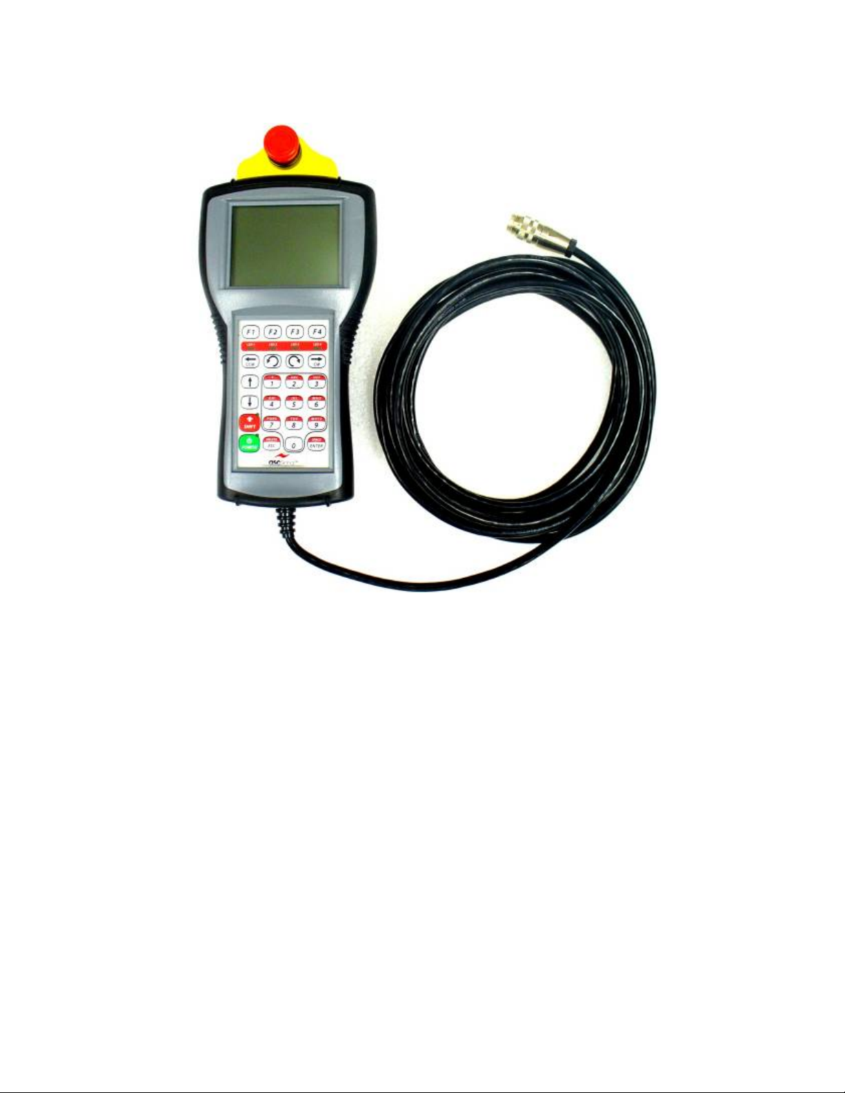
Local control from the outdoor unit through an advanced handheld unit
Automatic installation commissioning assistance
10/100 BaseT Ethernet interface for external M&Cs (via the IDU)
Remote control through network-based and serial-port-based communications protocols, including both legacy
protocols and SNMP.
Integral beacon receiver interfaces to support ASC Signal’s patented three-point peaking step-track and
SmarTrack® hybrid feedback/predictive program tracking algorithms.
NORAD and Intelsat program tracking
Optional integrated subreflector tracking (SRT) capability for high-accuracy Ka-band tracking, including hybrid
main dish and SRT positioning and tracking
The NGC is physically divided into an Indoor Unit (NGC-IDU) and an Outdoor Unit (NGC-ODU), connected by a dedicated
multimode optical fiber link. The NGC-IDU is a 3RU 19-inch rackmount chassis that is mounted inside the equipment
shelter or building. It provides the user interface and the interface to the tracking receivers. All NGC variants have the
same NGC-IDU package.
The NGC-ODU is packaged in multiple layouts based on application. All are generally mounted outside, on the positioned,
pedestal or tripod mount. Depending on the ordered chassis variant, the NGC-ODU may use 208VAC or 380VAC three-
phase wye power, or 230VAC single-phase power. The NGC-ODU may use common or separate sources for technical
and service power, as desired by the customer.
The functional allocation between NGC-IDU and NGU-ODU follows one basic principle: the indoor unit generates all
pointing commands and the outdoor unit executes them. All tracking functions are isolated to the NGC-IDU, which as
mentioned is indoors, where the beacon receiver or other signal measurement device will be located. All motion control
functions are isolated to the NGC-ODU, which is located on the positioner or pedestal, allowing the termination of all local
control cables after short runs and minimizing the interconnection between indoor and outdoor to AC power, transmit and
receive signals, and a single control fiber.

7580368_Rev D Page 6of 89
Unlike many previous systems, pointing commands from the NGC-IDU to the NGC-ODU are always given in horizon-
oriented coordinates (that is, true azimuth and true elevation). The NGC-ODU software performs all necessary coordinate
transformations to determine “local” azimuth and elevation position commands, and to provide feedback in both local and
horizon-oriented coordinate frames.
No configuration of the dedicated link between NGC-IDU and NGC-ODU is required. This avoids the need for the installer
to understand TCP/IP networking configuration.
I.II Personnel Requirements NOTICE
THE INSTALLATION, MAINTENANCE OR REMOVAL OF AN ANTENNA REQUIRES QUALIFIED,
EXPERIENCED PERSONNEL.
ASC SIGNAL CORP. INSTALLATION INSTRUCTIONS HAVE BEEN WRITTEN AND ILLUSTRATED FOR SUCH
PERSONNEL.
ANTENNA SYSTEMS SHOULD BE INSPECTED AT LEAST ONCE A YEAR BY QUALIFIED PERSONNEL TO
VERIFY PROPER INSTALLATION, MAINTENANCE AND CONDITION OF THE EQUIPMENT.
ASC SIGNAL CORP DISCLAIMS ANY LIABILITY OR RESPONSIBILITY FOR THE RESULT OF IMPROPER OR
UNSAFE INSTALLATION OR MAINTENANCE PRACTICES.
I.III Miscellaneous Notices
Proprietary Information
The technical data contained herein is proprietary to ASC Signal Corporation. It is intended for use in the installation,
operation, and maintenance of ASC Signal equipment. This data shall not be disclosed or duplicated, in whole or in part,
without the expressed written consent of ASC Signal Corporation.
Installation Notice
Installation, maintenance, or removal of the hardware described in this manual requires qualified and experienced
personnel. ASC Signal installation instructions are written for such personnel. Qualified personnel MUST perform
proper installation and maintenance of the equipment, and MUST verify the condition of the equipment at initial
installation and periodically thereafter.
NOTE: ASC Signal is NOT liable or responsible for results of improper or unsafe installation and maintenance practices.
All designs, specifications, and availability of products are subject to change without notice.
IMPORTANT: What to Know When You See OPTION:
Any time you see OPTION:, this means that the information following it is related to an optional element (in either
hardware or software) that may or may not apply to the arrangement of your particular NGC Unit. Please note that if you
see an option that you do not have but would like to purchase, please contact ASC Signal.
I.IV Warning Symbols
Various components of this System may display safety symbols. Be sure to use extreme caution when operating
components with any of the following safety symbols:
Certains éléments du système montreront peut-être des symboles de sécurité. Faites très attention à faire marcher tous
les éléments qui tiennent les symboles de sécurité suivants:
OR WARNING! HAZARDOUS MOVING PARTS! KEEP FINGERS AND OTHER BODY PARTS AWAY!
AVERTISSEMENT! PIÈCES MOBILES DANGEREUSES! GARDEZ LES DOIGTS ET LES AUTRES PARTIES DU
CORPS HORS D’ATTEINTE!
WARNING! RISK OF ELECTRIC SHOCK!
AVERTISSEMENT! RISQUE D’ÉLECTROCUTION!
WARNING! REFER TO MANUAL
AVERTISSEMENT! SE RÉFÉRER AU MANUEL D’UTILISATION.

7580368_Rev D Page 7of 89
I.V Safety Terms Summary
The following safety terms may appear on the product:
Les termes de sécurité suivants peuvent apparaître sur le produit:
DANGER—Indicates an immediately accessible injury hazard is present as you read the marking, and failure to take
precautions could result in loss of life
DANGER—Cette indication signale un risque de blessure immédiat et qui peut être mortel.
WARNING—Indicates a nearby injury hazard that is not immediately accessible as you read the markings, and failure to
take precautions could result in personal injury and/or loss of life
AVERTISSEMENT—Cette indication signale un risque de blessure non immédiat mais qui peut être mortel.
CAUTION—Indicates a potential hazard to property, including the product
PRUDENCE—Indique un risque pour l’environ du produit, le produit inclus.
The following safety symbols and terms may be used in this manual:
Les symbols et les termes suivants de sûreté peuvant être employés en ce manuel:
WARNING! Statements identify conditions & practices that could result in injury or loss of life.
AVERTISSEMENT! Les rapports d’avertissement identifient les conditions ou les pratiques qui pourraient avoir comme
conséquence les dommages ou la perte de la vie.
RISK OF ELECTRIC SHOCK!
RISQUE DE DÉCHARGE ÉLECTRIQUE!
I.VI Summary of Safety Precautions
The following safety precautions are not related to any specific procedure, and so will not appear elsewhere in this
manual. Ensure all personnel understand & apply these precautions in all phases of installation, operation, &
maintenance. Failure to do so may result in loss of life.
KEEP AWAY FROM LIVE CIRCUITS: Personnel must observe all applicable safety regulations at all times. Ensure
power is disconnected or removed from the unit BEFORE replacing any components. Potential hazards may exist even
though the power control switch is in OFF position. Capacitors retain electrical charges. Always REMOVE POWER & use
test equipment to confirm a circuit is at ground potential BEFORE touching it. NEVER reach into or enter an enclosure to
service or adjust the equipment until the absence of power has been confirmed.
DO NOT SERVICE OR ADJUST ALONE: Under NO circumstances should ANY person reach into or enter the
enclosure for the purpose of servicing or adjusting the equipment except in the presence of someone who is capable
of rendering aid in case of an accident/emergency.
RESUSCITATION: Personnel working with or near high voltage should be familiar with resuscitation methods (CPR
and/or AED). CPR info may be obtained from medical personnel. For AED (Automated External Defibrillator) information,
contact supervisor or hosting administration for details on the availability and/or location of an AED unit at your worksite.
ELECTROSTATIC DISCHARGE PRECAUTION
This equipment contains electrostatic discharge (ESD) sensitive devices. ESD sensitive equipment handling methods
must be used to prevent equipment damage during handling and servicing.
ESSENTIAL HEALTH AND SAFETY REQUIREMENT
Refer to document “P/N 240117—Essential Health and Safety Requirements”.

7580368_Rev D Page 8of 89
I.VII THINGS TO NEVER DO
NEVER touch circuits or reach into an enclosure until the disconnection of power and absence of charge has been
confirmed
NEVER service or adjust equipment alone. Electric shock can lead to cardiac arrest. Presence of immediate aid gives
you a 90% chance of survival, but this drops by 10% with every passing minute. After 5 minutes, resuscitation
without permanent heart and/or brain damage is nearly impossible. Consider this: Without the immediate aid of
CPR or an AED, what are the odds you will be found and successfully revived in under 5 minutes?
NEVER ignore warning symbols or fail to read safety signs
NEVER skip steps in a sequence, unless specifically instructed to do so by the manual, software, and/or authorized
ASC Tech Support Personnel. Aside from risking harm to yourself, you risk doing permanent damage to the equipment
NEVER touch or stand near any potentially moving parts (even if they are not in motion at the time) when the unit is in
operation or powered on, as they may move without warning
NEVER stand underneath any object while it is being lifted
NEVER remove, disable, or exceed the unit’s safety, software, security, or movement limits, unless specifically
instructed to do so by the manual, software, and/or authorized ASC Tech Support Personnel. The careless disabling of
such safeguards is one of the most common causes of serious equipment damage during installation and operation
I.VIII Parts Verification
STOP! READ BEFORE BEGINNING ASSEMBLY OR INSTALLATION!
Upon receipt of your order, the shipment should be verified to ensure that all parts have reached your site. This process
should occur before the installation process begins. ASC Signal Corporation thoroughly inspects and carefully packs all
equipment before shipment. If you find that there are missing or damaged components, please refer to the step-by-step
instructions (located in back of this manual) on how to properly report equipment loss or damage. When you have
received your order, verify that all parts contained in the shipment correspond to the parts listed on your packing
slip/inventory.

7580368_Rev D Page 9of 89
1.0 Operation of Handheld Controller
The NGC-ODU may be controlled from the pedestal base, via use of the Handheld Controller (shown below in
Figure 1-1).
Figure 1-1: Handheld Controller with Connection Cable
The Handheld Controller is QTERM-G55 model controller with a 320x240 pixel, LCD transflective FSTN,
grayscale (16 shades) display. The display screen employs a light emitting diode (LED) backlight. The LED
provides excellent readability under most lighting conditions and can operate in either portrait or landscape
mode. The FSTN contrast is software-controlled and compensated for temperature. The transflective display
provides excellent sunlight or high ambient light readability. The backlight also provides white lighting for high
contrast and easy readability. Brightness of the backlight and FSTN contrast are controlled by software. User
input occurs through a rugged 24-key membrane keypad with steel domes. This 24-key keypad allows for
function/soft keys, four-way directional control and alphanumeric data entry. Certain keys can perform alternate
functions when the shift key is enabled (refer to Table below Figure 1-2 for specifics).
Setup parameters are password protected in the handheld terminal and can only be accessed by logging
into the handheld. In most cases, the handheld terminal will be shipped with the Persistent Password
already logged in. If the handheld terminal requests that you login, use one of passwords listed below.
The “Temporary” password will automatically logout when power to the handheld is disconnected. The
“Persistent” password will keep the handheld logged in until the user forces it to logout. You will need the
following passwords to access the system:
ODU/Handheld TEMPORARY Installer Password:JFQB23
ODU/Handheld PERSISTENT Admin Password:32BQFJ
The handheld terminal’s LCD screen is a backlit graphical interface. The LCD displays messages to
indicate the antenna functions and status. Antenna functions and status include whether or not the
antenna is moving, if a satellite signal is found, if a signal is lost, etc. The LCD indicates soft key
functions on a given screen. Additionally, the LCD alerts you if a system fault occurs, and allows you to
troubleshoot the antenna.

7580368_Rev D Page 10 of 89
DO NOT LEAVE HANDHELD SCREEN IN DIRECT SUNLIGHT! Screensaver does not protect screen from
sunlight. Prolonged exposure to sunlight will cause screen to become temporarily washed out, making it unusable
until returned to shade for a time. If exposed for too long, such as an entire day, screen may be permanently damaged.
The screen saver becomes active:
After 10 minutes = screen dims
After 30 minutes = screen saver comes on
After 50 minutes = screen goes dark
To reactivate the dark screen, simply press any key on the handheld.
The user operates the handheld terminal by using soft keys and implemented by pressing function keys. The
handheld terminal has four function keys, labeled F1–F4. When one of these four keys has a specific function,
the function for that key is displayed above it on the LCD. If a key does not have a function for the current
screen, field, and/or mode, then the space above it on the LCD will remain blank.
Operational configuration is used to indicate the basic system setup of the NGC-ODU. It usually matches the
role the antenna system plays. It is primarily a setting about what kinds of equipment are expected to be
present in the system.
Fixed antenna is a system whose geographic location is not normally assumed to change. The location
is generally entered by hand using the handheld or the NGC-IDU. In this configuration, the system will
use the attitude sensor if it has access to it, but does not require it to be present for normal operation. A
fixed antenna may also include an SRT (this is called a ‘combined system’) but of course does not
require it.
Mobile antenna paused is a system with a changing location, including frequent relocations, but is
normally used on the pause, and which includes as AS-1, which is equipment to ascertain the geographic
location of the system as a regular part of operation. This operational configuration enables certain extra
functions designed to assist in operation.
SRT-only is a system with a main reflector that is not motorized and cannot move, but has an SRT
installed
SRT Slave Only is reserved for future applications
Other settings are reserved for future applications.
LocalRemote indicates which entity has control of the system (can move the antenna, change parameters).
Other modes are as follows:
Local means the system is under control of the IDU front panel or the IDU remote front panel software
Remote means the system is under control of the SNMP Agent
Local handheld means the system is under control of the handheld terminal
1.1 Handheld-to-ODU Connection
To connect Handheld Controller to the NGC-ODU:
1. Remove the tethered plug, normally plugged into J3 (on the underside of the ODU cabinet)
NOTE:
Removing tethered plug from J3 will lock out all control (the same as pressing an ESTOP button), prohibiting
antenna movement until either Handheld cable is plugged in J3 or tethered plug is returned to J3.
2. Plug the Handheld Controller cable (as shown in Figure 1-1) into J3
3. Handheld Controller should power on automatically, so there is no need to press the power button
To ENGAGE an ESTOP:
Press in any red ESTOP button
Depending on the options for your particular system/equipment, ESTOP buttons can be present in any
number of locations, such as on the ODU, IDU, Handheld Controller, or mounted on nearby walls (or other
structures)
NOTE:
Engaging any ESTOP button will lock out all movement/control for antenna. (Also locks out movement/control
from IDU)
To RELEASE an ESTOP:
Handheld & IDU ESTOP buttons are released by turning ESTOP knob Clockwise until it pops out
ESTOP on side of ODU (or at optional ESTOP stations) can be released by pulling out the button

7580368_Rev D Page 11 of 89
1.2 Handheld Keypad Breakdown
Figure 1-2: Handheld Keypad
Image Button Title Function/Description
POWER BUTTON
(ON/OFF)
Standby power button for handheld (does not affect power to NGC-ODU)
NOTE: If power to Handheld Controller is turned OFF, the system will return to “Local Mode” with
the IDU in control of the system. When power is returned to Handheld, the ODU will return system
to “Local Handheld Mode,” in which the Handheld has sole control (IDU is locked out).
Function Key 1 (F1) Performs different functions, depending on what is on screen in the Button
Ribbon immediately above key
Function Key 2 (F2) Performs different functions, depending on what is on screen in the Button
Ribbon immediately above key
Function Key 3 (F3) Performs different functions, depending on what is on screen in the Button
Ribbon immediately above key
Function Key 4 (F4) Performs different functions, depending on what is on screen in the Button
Ribbon immediately above key
Azimuth
Counterclockwise
(CCW/Left Arrow)
On Jog Screen this key turns antenna Counterclockwise, decreasing the Az
value. On other screens, it is used to navigate the cursor/screen
Azimuth Clockwise
(CW/Right Arrow)
On Jog Screen this key turns the antenna Clockwise, increasing the Az value.
On other screens, it is used to navigate the cursor/screen
Polarization
Counterclockwise
(Circle Arrow CCW)
Turns Pol Counterclockwise (OPTION: this key is used only if Pol drive is
present)
Polarization
Clockwise (Circle
Arrow CW)
Turns Pol Clockwise (OPTION: this key is used only if Pol drive is present)
Elevation UP (Up
Arrow)
On Jog Screen this key increases Elevation. On other screens, it is used to
navigate cursor/screen
Elevation DOWN
(Down Arrow)
On Jog Screen this key decreases Elevation. On other screens, it is used to
navigate cursor/screen
SHIFT Allows certain keys to assume secondary functions (such as 1, 2, ENTER, and
ESC)
Number Pad 0, 1-9. Additionally, if pressed with SHIFT, #1 key will create decimal point
(.) and #2 key will create a minus/negative symbol (-). On the Jog Screen,
these keys are used to select movement speed for the antenna
ENTER (Space if
pressed with SHIFT)
Allows you to finalize/input values, edit a dropdown list, or engage a field.
Pressed with SHIFT, it allows you to enter a space on the screen (like the
spacebar on a computer keyboard)
Escape/ESC (DELETE
if pressed with SHIFT)
Used to cancel an action or disengage a field. Pressed with SHIFT, it becomes
the DELETE key (functioning like a delete key on a computer keyboard)
ESTOP (Emergency
Stop)
Engaging ESTOP will immediately stop all movement of antenna. Press to
engage. To release, turn clockwise until you feel button release (will pop upon
release)
LED Bar (LED 1 – LED 4) NOT USED

7580368_Rev D Page 12 of 89
1.3 Handheld Screens Breakdown
ThefollowingdiagramillustratestheGeneralMenuTree,meaningtheorderofscreens/pagesfortheNGC‐ODU
HandheldController.
Figure 1-3: Handheld Controller Menu/Screen Tree
While navigating the screens of the Handheld Controller, you may notice certain icons, graphical conventions,
or occurrences related to navigation and editing of certain fields. In the below table (Table 1.1), these are
illustrated and explained.
Table 1.1: Important Screen Icons
Image Name Description
Dropdown Menu Arrow This icon, when available, indicates the presence of dropdown menu.
Selecting this icon will open dropdown menu. Navigate to a field that
has this icon and press ENTER to display dropdown list of commands.
Use UP/DOWN keys to navigate/highlight selections from the list, and
ENTER to select a highlighted command from the list.
Long-Dash Circulating Line
(Navigation) Indicates that you have navigated to the enveloped field. This line will
move across the screen until you select a field for editing, in which case
this line will be replaced by the Short-Dash Circulating Line.
Short-Dash Circulating Line
(Editing) Indicates you have selected a field for editing. Line will envelop a field
selected for editing, but not move across the screen. You must exit
editing, returning to Long-Dash Circulating Line, to continue navigating
screen.

7580368_Rev D Page 13 of 89
1.3.1 General User Screens
This section explains handheld interface screens available to non-privileged users, meaning general
(unqualified) personnel. For screens meant for qualified technical personnel, refer to Section 1.3.2.
If you are a General User, DO NOT use this manual. General users should refer to manual #7581776.
1. HOME SCREEN
The HOME SCREEN (Figure 1-4a and related table, which describes the fields marked by numbers in the
illustration) is the default screen for the Handheld Controller. You will see this screen upon initial
connection and power up of the Handheld Controller. All navigation paths explaining how to reach the
screens that follow will start at the HOME SCREEN. Pressing MORE (F4) allows the user to change the
soft/function keys.
1
5
4
3
2
9876
Figure 1-4a: Home Screen
Figure 1-4b: Button Ribbon Options, HOME SCREEN 2
Figure 1-4c: Button Ribbon Options, HOME SCREEN 3
Number Description
1 Current Time
2 Current global Azimuth angle
3 Current global Elevation angle
4 Current global Polarization angle
5 Current working satellite index
6 F1: Go to JOG SCREEN
7 F2: Go to PARAMETERS SCREEN
8 F3: Go to CURRENT FAULTS SCREEN
9 F4: go to next Button Ribbon for MORE options (see Figure 1-4b)
10 F1: go to MESSAGE LOG
11 F2: go to INSTALLATION SCREEN
12 F3: go to DIAGNOSTIC COMMANDS SCREEN
13 F4: go to MORE Button Ribbons options (Figure 1-4c)
14 F1: go to PASSWORD SCREEN
15 F2: go to SYSTEM INFORMATION (SYSINFO) SCREEN
16 F4: go back to PREVIOUS Button Ribbon options

7580368_Rev D Page 14 of 89
2. Jog [Main Dish] SCREEN
The JOG SCREEN (see Figure 1-5 and related table) is used to move the antenna. This screen can be
used to jog any axis, as well as to see angle feedback from the encoders or resolvers, and to view any
faults or alarm conditions. The JOG screen can also be used to change the Jog speed (10%-90%) for the
Az and El axes using the number pad.
Path: HOME SCREEN -> F1 (JOG)
Figure 1-5: Jog Screen
Number Description
1 Current coordinate for Az in Global or Local, depending on indicated mode (see #11 in this table)
2 Current coordinate for El in Global or Local, depending on indicated mode
3 Current coordinate for Pol (if present) in Global or Local, depending on indicated mode
4 Az vs. Time Plot for the last 10 minutes
5 F1: Go BACK to HOME SCREEN (see Figure 1-4a)
6 Use ESC key to toggle between SRT & Main Dish Jog (if necessary). Use ENTER key to toggle
between Local & Global Coordinate systems (Help text only). Title will change.
7 F4: move to GoTo SCREEN (see Figure 1-6)
8 El vs. Time Plot for the last 10 minutes
9 This area for the three fields (see #1-3 in this table) is reserved for display of Limits & Faults.
Press SHIFT key to clear the displayed faults. See Appendix C for values.
10 Current Jog Speed: 10% to 90%
11 Indicates whether displayed coordinates are from Local (LCL) or Global mode
To manually jog the antenna, perform the following actions:
a. From Home Screen, press F1 (JOG) on Handheld. In the event that “JOG” is not available from Home
Screen, press F4 (MORE) and press corresponding Function Key (F1-F4) below the screen icon
b. Press ENTER on Handheld Controller to switch between LOCAL coordinates & GLOBAL coordinates
Local Coordinates: local coordinates for mount
Global Coordinates: are relative to true north and the horizon
c. Press DOWN arrow key to move Elevation down
d. Press UP arrow key to move Elevation up
e. Press LEFT (CCW) & RIGHT (CW) arrow keys to move antenna CCW and CW in Az. When pressing
LEFT (CCW) arrow key, antenna should rotate counterclockwise when viewed from above. Az pointing
angles should decrease on Handheld. Reverse occurs for RIGHT (CW) arrow key
f. Press ESTOP button on top of Handheld Controller, side of ODU, or at an optional ESTOP station to
lock out any further antenna movement. (Also locks out movement/control from NGC-IDU)

7580368_Rev D Page 15 of 89
3. GoTo SCREEN
The GoTo SCREEN (Figure 1-6), same as the JOG SCREEN, may also be used to move the antenna.
However, this screen is more precise and less labor intensive than the JOG SCREEN. With the GoTo
SCREEN, the user can edit the Az, El, and/or Pol fields, as well as command/execute antenna movement
with the GoTo AZ, EL, POL soft-key (F4).
Path: HOME SCREEN -> F1 (JOG) -> F4 (GoTo)
Figure 1-6: GoTo Screen
Number Description
1 F1: Go BACK to JOG SCREEN (see Figure 1-5)
2 F2: Applies current Az, El, & Pol coordinates to the Target Az, El, & Pol. Antenna will stop.
3 Indicates system is in Local Handheld mode. The mode can also be changed here
4 F4: Physically move the antenna to the Target Az, El, & Pol coordinates
5 Displays Target Pol (if Pol drive present) in Global coordinates. This may be edited as needed
6 Displays Target El in Global coordinates. This may be edited as needed
7 Displays Target Az in Global coordinates. This may be edited as needed
8 As on JOG SCREEN, this area reserved to display limits & faults for (Main Dish only)
9 These 3 fields are the same as items 1-3 in Figure 1-4a

7580368_Rev D Page 16 of 89
4. Parameters SCREENS & PAGES
The Handheld controller has dozens of screens which allow the advanced user to view almost all of the
NGC-ODU’s configuration parameters. The basic user, however, is authorized to view only a handful of
these parameters.
This section provides you with some representative examples. The DETAILED STATUS screens (Figures
1-7a & 1-7b) display lists of parameters that are associated with attitude, site location, current location,
operational configuration, and any faults/alarms associated with said parameters. See Appendix C (Table
C.1) for all parameter field descriptions.
Path: HOME SCREEN -> F2 (PARAMETERS)
Figure 1-7a: Parameters Screen
Number Description
1 10 fields display current page Parameters. All Parameter pages display up to 10 parameters each
(see Appendix C)
2 Use ARROW keys to navigate to field. Input desired page # to jump to another page (you may need
to check SHORTCUTS page for Parameter page #s)
3 F1: Return to HOME SCREEN
4 F3: Go to next PARAMETERS page
5 F4: Go to SHORTCUTS page

7580368_Rev D Page 17 of 89
2
1
543
Figure 1-7b: Parameters Screen (Edit Mode)
6 987
Figure 1-7c: Button Ribbon Options, Parameters Edit Mode 2
Number Description
1 Jump to a different Parameter page by inputting page # and pressing ENTER
2 F1: Move cursor back to delete (works the same as backspace key on a computer keyboard)
3 F2: Move cursor to the beginning/HOME of a selected field
4 F3: Move cursor to the END of a selected field
5 F4: Go to next Button Ribbon for MORE options (see Figure 1-7c)
6 F1: Clear a selected field
7 F2: go to SYMBOLS page
8 F3: INSERT a character into a selected field
9 F4: go back to PREVIOUS Button Ribbon options

7580368_Rev D Page 18 of 89
5. Current Faults SCREEN
The CURRENT FAULTS SCREEN (Figure 1-8a) provides a list of all active faults the NGC-ODU might
have. Take note that any faults associated with the NGC-IDU will not be listed in this manual. Refer to
Appendix A (Table A.2) for a list of Faults and their meanings
Path: HOME SCREEN -> F3 (CURRENT FAULTS)
1
3
54
9
6 7
2
8
Figure 1-8a: Current Faults
Figure 1-8b: Button Ribbon Options, Current Faults 2
Number Description
1 Current FAULT VECTOR being viewed
2 List of Active Faults
3 First column of FAULTS
4 F1: Return to HOME SCREEN
5 F2: Return to previous FAULT SCREEN page
6 F3: Go to the next FAULT SCREEN page
7 F4: go to next Button Ribbon for MORE options
8 Second column of FAULTS (if needed)
9 Show Parameter Page # for FAULT SCREEN
10 F1: go to SHORTCUTS SCREEN
11 F4: go back to PREVIOUS Button Ribbon options

7580368_Rev D Page 19 of 89
6. Message Log SCREEN
The MESSAGE LOG SCREEN (Figure 1-9) can be used to view a list of historical pop-up messages going
back to the last time power was applied to the Handheld controller.
Path: HOME SCREEN -> F4 (MORE) -> F1 (MESSAGE LOG)
Figure 1-9: Message Log
Number Description
1 Time of Fault: measured in seconds since midnight on 1-1-1970
2 A series of Question Marks indicates the Time of Fault is not available
3 List of Logged Messages (use UP/DOWN Arrow Keys to scroll through if needed due
to length)
4 F1: Go to HOME SCREEN
5 F2: PAGE UP (if needed, due to length of list)
6 F3: PAGE DOWN (if needed, due to length of list)
7 F4: Clear Log of all current messages
This manual suits for next models
7
Table of contents
Other ASC Signal Antenna manuals
Popular Antenna manuals by other brands

Panorama Antennas
Panorama Antennas LPB-6-60-NJ installation instructions

Labgear
Labgear LABHG48A user guide

Honeywell Home
Honeywell Home AlarmNet CELL-ANT3dBPK installation guide

RCA
RCA ANT3036W - ANT - TV Installation directions

Radio Shack
Radio Shack VU-120XR owner's manual

Winegard
Winegard FlatWave AIR user manual