Sematron Holkirk RM120 User manual

Sandpiper House, Aviary Court, Wade Road, Basingstoke, Hampshire, RG24 8GX, UK
www.sematron.com Making waves...
Operation Manual
Rev A. Feb 11.

Sandpiper House, Aviary Court, Wade Road, Basingstoke, Hampshire, RG24 8GX, UK
www.sematron.com Making waves...
Operation Manual
Rev A. Feb 11.
Installation Instructions
RM120 Drive away Terminal
Page 2 of 19
The distribution of this document is controlled by Holkirk Communications Ltd. Print date 08/01/2011
TABLE OF CONTENTS
1. Overview .................................................................................. 4
2. Installation and Set-up .................................................................................. 4
3. Controller Installation .................................................................................. 5
4. Maintenance .................................................................................. 5
5. Spares And Replacement Parts .................................................................................. 5
6. Manual Over Ride .................................................................................. 6
7. Overall Dimensions .................................................................................. 8
8. Mounting Bracket Positions .................................................................................. 9
9. Addendum ................................................................................ 11
10 Wiring diagrams ………………………………………………………….17

Sandpiper House, Aviary Court, Wade Road, Basingstoke, Hampshire, RG24 8GX, UK
www.sematron.com Making waves...
Operation Manual
Rev A. Feb 11.
Installation Instructions
RM120 Drive away Terminal
Page 3 of 19
The distribution of this document is controlled by Holkirk Communications Ltd. Print date 08/01/2011
Warranty
LIMITED TWELVE (12) MONTH WARRANTY
This Holkirk Communications Ltd equipment is warranted to be free from defects in material and
workmanship under normal use and service. Holkirk Communications Ltd shall repair or replace
defective equipment, at no charge, or at its option, refund the purchase price, if the equipment is
returned to Holkirk Communications Ltd not more than twelve (12) months after shipment.
Removal or reinstallation of equipment and its transportation shall not be at cost of Holkirk
Communications Ltd except Holkirk Communications Ltd shall return repaired or replaced
equipment freight prepaid.
This Warranty shall not apply to equipment which has been repaired or altered in any way so as to
affect its stability or durability, or which has been subject to misuse, negligence or accident.
This Warranty does not cover equipment which has been impaired by severe weather conditions
such as excessive wind, ice, storms, lightning, or other natural occurrences over which Holkirk
Communications Ltd has no control, and this Warranty shall not apply to equipment which has been
operated or installed other than in accordance with the instructions furnished by Holkirk
Communications Ltd.
Claimants under this Warranty shall present their claims along with the defective equipment to
Holkirk Communications Ltd immediately upon failure. Non-compliance with any part of this claim
procedure may invalidate this warranty in whole or in part.
THIS WARRANTY IS EXPRESSLY IN LIEU OF ALL OTHER AGREEMENTS AND WARRANTIES, ANY IMPLIED
WARRANTY OF MERCHANTABILITY OR FITNESS FOR A PARTICULAR PURPOSE IS LIMITED IN DURATION
TO THE DURATION OF THIS WARRANTY. HOLKIRK COMMUNICATIONS LTD DOES NOT AUTHORISE ANY PERSON
TO ASSUME FOR IT THE OBLIGATIONS CONTAINED IN THIS WARRANTY AND HOLKIRK COMMUNICATIONS LTD
NEITHER ASSUMES NOR AUTHORISES ANY REPRESENTATIVE OR OTHER PERSON TO ASSUME FOR IT ANY
OTHER LIABILITY IN CONNECTION WITH THE EQUIPMENT DELIVERED OR PROVIDED.
IN NO EVENT SHALL HOLKIRK COMMUNICATIONS LTD BE LIABLE FOR ANY LOSS OF PROFITS, LOSS OF USE,
INTERRUPTION OF BUSINESS, OR INDIRECT, SPECIAL OR CONSEQUENTIAL DAMAGES OF ANY KIND.
In no event shall Holkirk Communications Ltd be liable for damages in an amount greater than the
purchase price of the equipment.
Holkirk Communications Ltd has the right to void the warranty when the antenna is installed by
someone other than a certified installer.
Product Serial Number : ……………………………………………………….
Date Purchased : ……………………………………………………….
Holkirk Communications Ltd.
Unit 17 Pulloxhill Business Park
Greenfield Road
Pulloxhill
Bedfordshire
MK45 5EU
United Kingdom
Tel : +44 (0)1525 721118
Fax: +44 (0)1525 719734
Email : info@holkirk.com

Sandpiper House, Aviary Court, Wade Road, Basingstoke, Hampshire, RG24 8GX, UK
www.sematron.com Making waves...
Operation Manual
Rev A. Feb 11.
Installation Instructions
RM120 Drive away Terminal
Page 4 of 19
The distribution of this document is controlled by Holkirk Communications Ltd. Print date 08/01/2011
1. Overview – Technical Description
This RM120 is an azimuth over elevation positioning mount with motorised
polarisation control.
All axis feature simple and very robust 24V DC motor drives giving reliable, low
backlash, high and low speed motion controlled by either a jog controller or a fully
auto-pointing controller.
The optical layout is a dual offset Gregorian antenna which naturally produces
cross polarisation patterns which easily meet the 29-25 log theta requirement.
The bearings are sealed for life items that allow for highly accurate motion but
require no maintenance.
A manual over ride is provided for both azimuth and elevation axis to enable
stowing the antenna due to power or other failure.
The RF power amplifier(s) can be fitted either inside the cover, onto the framework
via mounting brackets or inside the vehicle itself.
System weight (without the RF) is 95 kg.
2. Installation and Set-up
The RM120 has been fully tested with the controller prior to shipment.
All position feedback, limit switches and motor speeds have been calibrated or set
at the factory and require no adjustment.
The positioner should be secured to the vehicle via sturdy brackets (See
addendum 1) attached between the exposed framework on the sides of the
antenna base framework and the vehicle roof gutters with the slide nuts provided
then connecting wave guide or HPA cables, connecting coax, control cable to
controller and power cables.
The vehicle roof structure should be stiff enough to prevent no more than a 0.5 dB
of TX gain loss in a 30mph gusting to 45mph wind.
Remove the lid and end sections of the shipping crate, adjust forklift forks to
roughly 1m apart or as wide as they will safely go if this cannot be achieved.
Sandpiper House, Aviary Court, Wade Road, Basingstoke, Hampshire, RG24 8GX, UK
www.sematron.com Making waves...
Operation Manual
Rev A. Feb 11.
Installation Instructions
RM120 Drive away Terminal
Page 5 of 19
The distribution of this document is controlled by Holkirk Communications Ltd. Print date 08/01/2011
Once suitable brackets are available (see attached drawing) these should be fitted
to the antenna roughly in the positions shown on the interface drawing with the
slide nuts provided.
Slings or ropes capable of withstanding the weight of the antenna (95kg) should
then be attached to the brackets, looped over the forks of the forklift and clamped
onto the forks to prevent them slipping off.
Raise the antenna to clear the vehicle roof by a minimum of 0.5m and manoeuvre
to the rear of the vehicle.
Whilst ensuring all cables are clear of mounting points, lower the positioner onto
the vehicle roof and line up all mounting holes.
Apply Loctite 242 or similar to all bolts and tighten to a torque of 13 – 15 Nm.
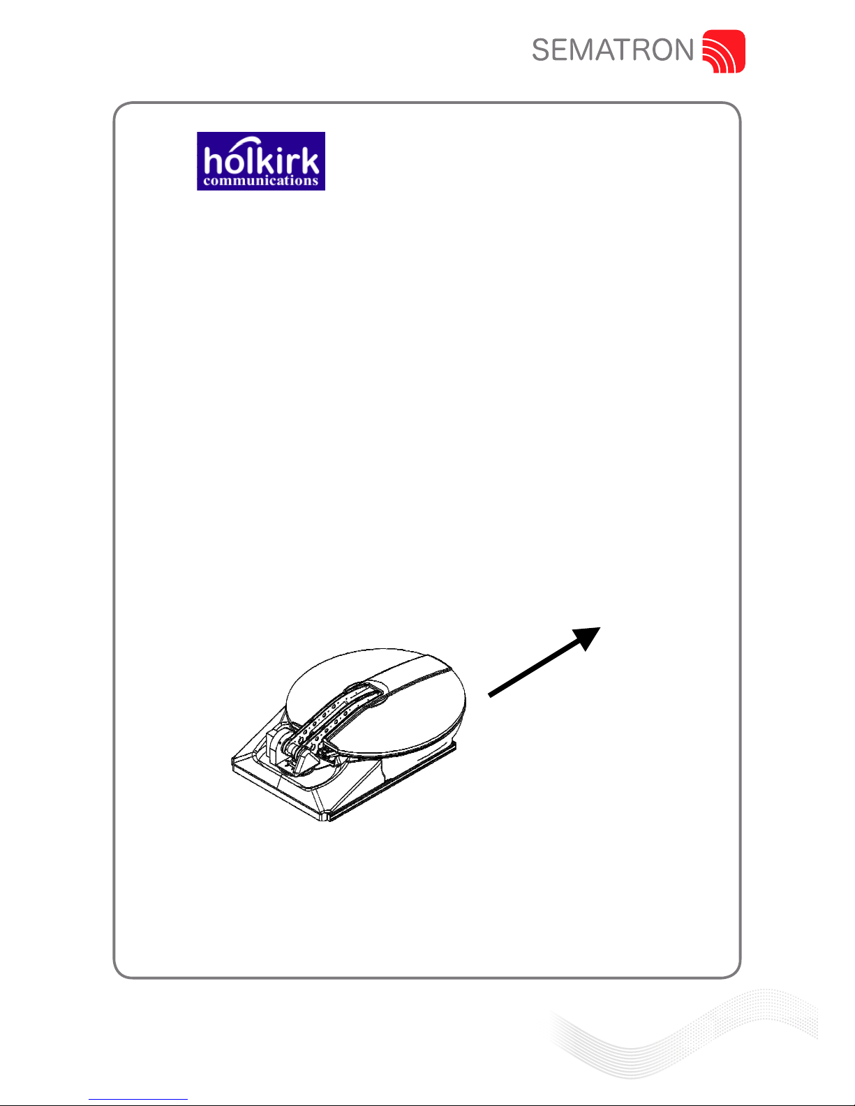
Direction of vehicle travel.
Antenna to be fitted facing this direction.

Sandpiper House, Aviary Court, Wade Road, Basingstoke, Hampshire, RG24 8GX, UK
www.sematron.com Making waves...
Operation Manual
Rev A. Feb 11.
Installation Instructions
RM120 Drive away Terminal
Page 6 of 19
The distribution of this document is controlled by Holkirk Communications Ltd. Print date 08/01/2011
3. IPoint ACU Controller Installation
Install controller into electronics rack and attach control cable ensuring it is
securely and fully pushed into its connector.
User Interface Unit (UIU)
The antenna controller may be operated directly from the front panel of the User
Interface Unit (UIU), a hand held controller or via a remote control link.
A Graphical User Interface (GUI) program is provided. This runs under Windows
2000 or Windows XP on any standard PC and communicates with the Ipoint ACU
via the remote control port on the front panel of the UIU.
A serial interface cable which connects from the UIU RJ11 connector to a standard
9 way female serial connector is provided with the UIU. This is wired to plug
directly into a standard 9 way D-type serial port on a PC.
The UIU only implements direct user comands.
• It allows the operator to select the reference and target satellites from the
existing list and to command Deploy.
• It allows the user to define the Final Pol and Final LNB settings following the
deploy and also allows direct control commands such as Standby, Jog,
Stow, Switch pol or Switch LNB. A complete list is given below.
The UIU does not allow the user to change parameters or to add or modify data in
the satellite database. These operations can be performed via the GUI.

Sandpiper House, Aviary Court, Wade Road, Basingstoke, Hampshire, RG24 8GX, UK
www.sematron.com Making waves...
Operation Manual
Rev A. Feb 11.
Installation Instructions
RM120 Drive away Terminal
Page 7 of 19
The distribution of this document is controlled by Holkirk Communications Ltd. Print date 08/01/2011
A typical auto-pointing usage sequence would be:
Ensure that satellite channel data exists for a number of locally visible satellites
including the required reference and, preferably, the target satellites. Data does not
need to exist for the target, but, if it is available, it allows confirmation that the
correct satellite has been acquired.
Note that if the UIU is to be used for selecting the Reference and Target satellites,
then those satellites must appear in the first 10 slots of satellite data Ensure that
the reference and target satellites are as required and that the final pol and final
LNB settings match the settings required to access the satellite after acquisition.
Command Deploy (from the UIU or GUI).
For manual or JOG functions
Accessing JOG ANTENNA puts the system into manual jog mode and the Az and
El axes can be jogged using the ^, v,> and < keys. Pressing enter again will toggle
the mode between (Az & El jog) and (Polarisation axis jog (using > and < keys)). If
the enter key is pressed while a ^, v, > or < key is already active then the speed will
change to fast.
This is not a latching function and the speed will revert to slow as soon as the enter
key is released. Clear will take the system back out of Jog mode.
4. Maintenance
The antenna should be fully visually inspected at the point of installation and
periodically there after at intervals of not more than 1 year. As the drives require no
maintenance or adjustment this procedure simply involves ensuring there are no
worn or damaged cables, that the waveguide is not damaged or perished and that
all fasteners are present and tightened to the correct torque level.
5. Spares and Replacement Parts
Since no maintenance is required, only electrical parts are recommended as
spares. These parts will not fail from activity, but may fail from environmental
exposure.
Sandpiper House, Aviary Court, Wade Road, Basingstoke, Hampshire, RG24 8GX, UK
www.sematron.com Making waves...
Operation Manual
Rev A. Feb 11.
Installation Instructions
RM120 Drive away Terminal
Page 8 of 19
The distribution of this document is controlled by Holkirk Communications Ltd. Print date 08/01/2011
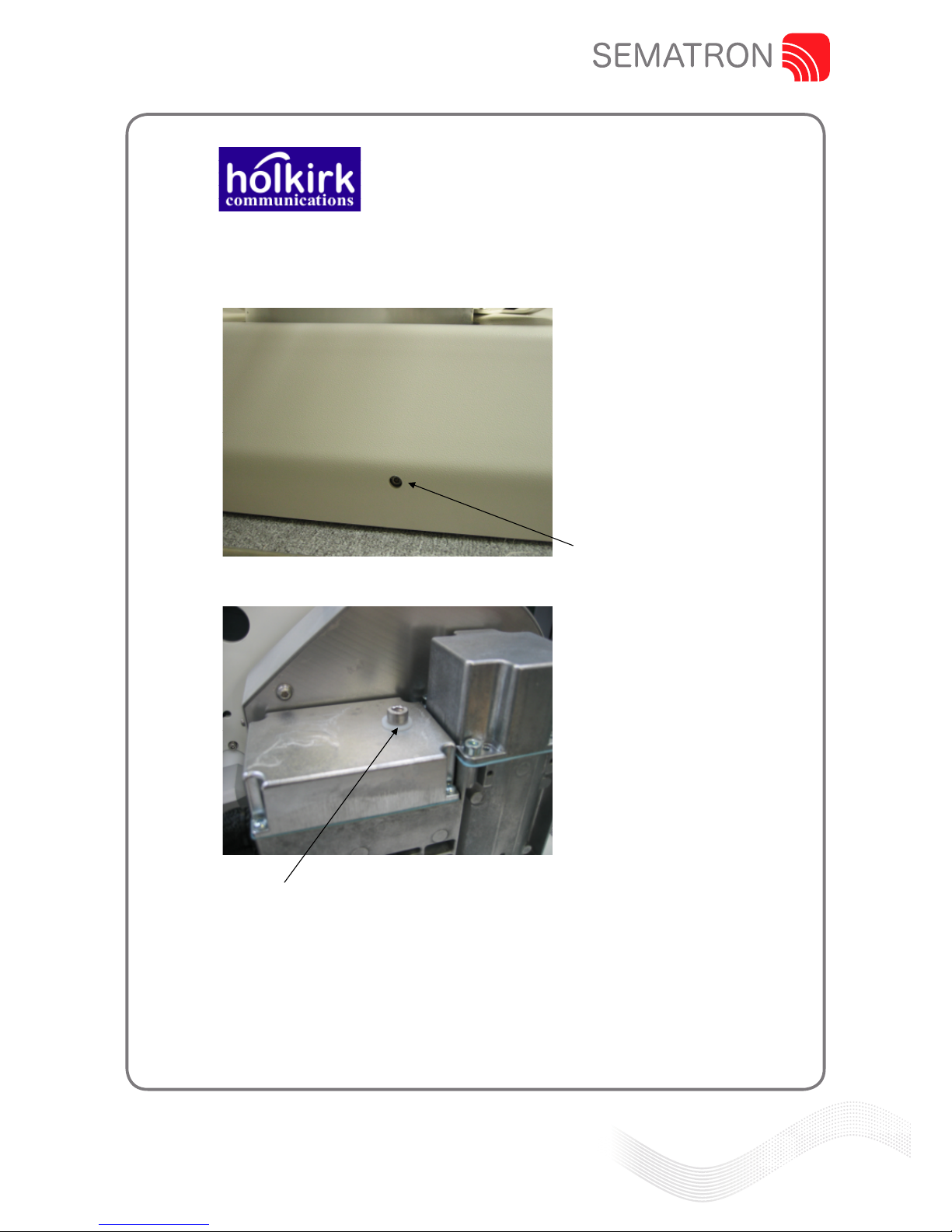
6. Manual Over Ride
Azimuth
Insert hexagon key
Elevation
Ensure that the DC power to the unit is switched off, remove the 8mm bolt &
sealing washer indicated, insert 4mm hexagon key into the shaft end & turn as
required.

Sandpiper House, Aviary Court, Wade Road, Basingstoke, Hampshire, RG24 8GX, UK
www.sematron.com Making waves...
Operation Manual
Rev A. Feb 11.
Installation Instructions
RM120 Drive away Terminal
Page 9 of 19
The distribution of this document is controlled by Holkirk Communications Ltd. Print date 08/01/2011
7. Overall Dimensions

Sandpiper House, Aviary Court, Wade Road, Basingstoke, Hampshire, RG24 8GX, UK
www.sematron.com Making waves...
Operation Manual
Rev A. Feb 11.
Installation Instructions
RM120 Drive away Terminal
Page 10 of 19
The distribution of this document is controlled by Holkirk Communications Ltd. Print date 08/01/2011
8. Mounting Bracket Positions

Sandpiper House, Aviary Court, Wade Road, Basingstoke, Hampshire, RG24 8GX, UK
www.sematron.com Making waves...
Operation Manual
Rev A. Feb 11.
Installation Instructions
RM120 Drive away Terminal
Page 11 of 19
The distribution of this document is controlled by Holkirk Communications Ltd. Print date 08/01/2011
Specification
Mechanical Data
Overall dimensions : 1.67m x 1.25m x 0.49m
Geometry : Gregorian offset, dual optic
Reflector material : SMC
Feed interface : WR 75
Azimuth range : +/- 185°
Elevation range : 10~90°
Operating temperature : -30°C ~ +60°C
Weight 95 kg (Depending on options)
Electrical Data
Receive
Polarisation : linear
Frequency band : 10,7 ~12,75 GHz
3dB beam width : 1,3°
Gain @ 12,5 GHz : 41,8 dBi
G/T (30° elevation) @ 12.5 GHz : 21 dBK
Transmit
Polarisation : linear orthogonal
Frequency band : 13,75 ~14,5 GHz
3dB beam width : 1,1°
Gain @ 14,25 GHz : 43 dBi
VSWR : 1,3 : 1 max
Isolation Rx / Tx (13,75~14,5 GHz) : 40 dB min
Isolation Tx / Rx (10,75~12,75GHz) : 75 dB min
Antenna approvals Eutelsat/Intelsat compliant
Power Requirements
Unit requires a regulated 24vdc supply with a 10amp current rating as a minimum
Options:-
1:1 Redundancy
Full Cover Set
Auto-Pointing Controller
Vehicle Mounting Kit
Sandpiper House, Aviary Court, Wade Road, Basingstoke, Hampshire, RG24 8GX, UK
www.sematron.com Making waves...
Operation Manual
Rev A. Feb 11.
Installation Instructions
RM120 Drive away Terminal
Page 12 of 19
The distribution of this document is controlled by Holkirk Communications Ltd. Print date 08/01/2011
Addendum
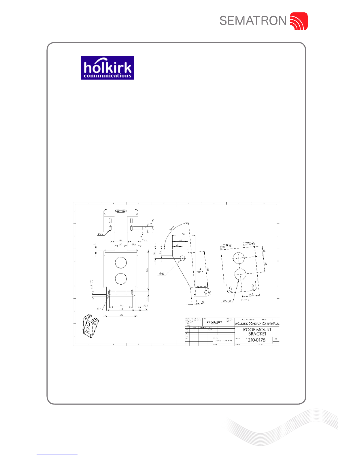
1. Holkirk Communications Ltd strongly recommends that vehicle
mounting brackets are purchased from Holkirk Communications Ltd at
the same time as purchasing the antenna for the specific vehicle
intended to be used. If mounting brackets are to be manufactured by
the customer then they should be made very robustly to ensure they
withstand vibrations from travelling over a long period of time and
should be regularly inspected to ensure they are free from cracks or
other deformation.
Below is an example drawing for mounting brackets suitable for fitting to a
Mercedes Vito Van.

Sandpiper House, Aviary Court, Wade Road, Basingstoke, Hampshire, RG24 8GX, UK
www.sematron.com Making waves...
Operation Manual
Rev A. Feb 11.
Installation Instructions
RM120 Drive away Terminal
Page 13 of 19
The distribution of this document is controlled by Holkirk Communications Ltd. Print date 08/01/2011
Addendum 2
Ipoint Operation Monitoring
The Ipoint Antenna control system is designed to be very simple to operate and is expected to be fully
automatic in acquiring the required satellite signals.
However the system does not provide very much user feedback if the satellite acquisition operation
does not complete.
This document is intended to provide method to gather information on the progress of the satellite
acquisition.
1 Serial Communication
To communicate with the Ipoint system a PC with a serial port is required. The information below
described the use of hyper-terminal as a "terminal emulator", but any similar program could be used
instead.
One unusual point about the serial interface is that the UIU front panel will keep trying to take control
of the interface. When this happens you may see “garbage characters” generated. To reduce the effects
of this type an extra “carrige return” evry 10 seconds or so, The normal serial parameters are
19200,n,8,1 but mobile systems which connect the UIU to a DVBRCS modem are typically set to
4800,n,8,1.
The Baud rate can be changed via the UIU front panel.
Press the buttons as follows:-
Down arrow *6 Display Shows "User Setup"
Enter Display Shows "Final Pol"
down arrow *4 Display Shows "GPS Output"
Enter Display Shows "4800"
Enter. Display Show "19200".
Clear. Return to main menu.
This baud rate change is not stored. The next time the system is power cycled the baud rate will
revert to normal operation.
The connection is taken from the RJ-11 front panel connector on the Ipoint User Interface Unit.
A cable can be supplied but connection details are shown below.
RJ-11 TO 9-PIN D-Type Socket ADAPTER CABLE
To connect a PC to the UIU Front Panel M&C connector use this adapter cable. Adapter
cables must be individually wired. Follow the pinout listed in table below.
The diagram shows the pinout for the RJ-11 connector, looking into the socket on the
panel. This is a 6 pin version of the RJ-11 connector, sometimes known as an RJ-12

Sandpiper House, Aviary Court, Wade Road, Basingstoke, Hampshire, RG24 8GX, UK
www.sematron.com Making waves...
Operation Manual
Rev A. Feb 11.
Installation Instructions
RM120 Drive away Terminal
Page 14 of 19
The distribution of this document is controlled by Holkirk Communications Ltd. Print date 08/01/2011
D Connector Signal RJ-11 Connector
Pin 1 Common Pin 5
Pin 2 Term Data IN Pin 3
Pin 3 Term Data OUT Pin 2
Pin 5 Ground Pin 1
Pin 6 Not Used Pin 4
Do Not Connect + 5VDC @ 100 mA Pin 6
Same table in RJ-11 order
D Connector Signal RJ-11 Connector
Pin 5 Ground Pin 1
Pin 3 Term Data OUT Pin 2
Pin 2 Term Data IN Pin 3
Pin 6 Not Used Pin 4
Pin 1 Common Pin 5
Do Not Connect + 5VDC @ 100 mA Pin 6
This diagram shows the pin order when viewed from
plug cable entry.
2 Normal Operation
The Ipoint's normal "deploy" operation is made up of several stages.
There is information provided at some stages which can be helpful to diagnose a system having
problems.
First start to capture the information on the serial port. (In hyper-terminal use the "Transfer\Capture
text" menu and provide a filename.) If you need assistance interpreting the information then it can be
e-mailed to support.europe@advantechamt.com .
Then type the command "
debugport 0
". This will instruct the system to provide additional dignostic
data.
Then type the command "
deploy
".
2.1 Unstow
No useful information about this step. The antenna is driven from the current position to the "unstow"
position.

Sandpiper House, Aviary Court, Wade Road, Basingstoke, Hampshire, RG24 8GX, UK
www.sematron.com Making waves...
Operation Manual
Rev A. Feb 11.
Installation Instructions
RM120 Drive away Terminal
Page 15 of 19
The distribution of this document is controlled by Holkirk Communications Ltd. Print date 08/01/2011
2.2 Orientation
During this step 3 pieces of information are gathered.
1. The GPS is read to get the current location on earth.
2. The magnetometer is read to get a heading angle for the platform. This is the geographical
direction that the antenna is pointing at the unstow position.
3. Then the antenna is driven to an elevation angle above the geostationary arc to take a "noise floor"
measurement.
Once this drive has been completed the GPS and the magnetometer readings can be checked.
To see the gps data type the command "
gps
". Check that the last line indicates that the signal is valid.
To check the magnetometer heading information type "
platform
". The third number is the heading
angle in degrees.
This number could be as much as +/- 20 degrees from the correct reading without stopping the
system working. If the error is greater than 20 degrees then this can cause problems.
If required the correct heading can be provided.
Type the command "
platform 0 0 zz
" where zz is the correct heading in degrees.
2.3 Satellite Sweep
The start of the satellite sweep is shown in the diagnostic data.
During this stage the antenna elevation and pol angles are set to the correct angles for the reference
satellite and a range of azimuth movement is swept looking for an RF signal.
If during this phase a messge is seen reporting a “
horizon scan
” has been started then this indicates
that no RF signal above the noise floor was detected during the sweep. This is an indication that there
is a problem with the LNB of L-band cabling from the LNB to the Ipoint ACU.
2.4 Peak on reference satellite
No diagnostic data is provided for this stage but the "cross scan" movements of the antenna can be
seen.
2.5 Identify reference satellite
At the beginning of this step the diagnostic data reports "
Looking at ww
" where ww is the longitude of
the reference satellite.
At the end of this stage there is a line of information which starts "
CTRL
" first number indicates the
satellite longitude being checked. The last number is the number of DVB channels checked.
The second to last number is the number of channels successfully decoded. The success number
should be more than half of the number of channels checked.
If less than half of the channels checked failed to be identified then the system will start to check
channels from other satellites. Once it completes the list of satellites the system will report “
walking
the arc
”. This is an indication that it found an RF signal but was unable to identify it as any known
satellite. In some cases the system will find a satellite which is not the reference satellite, but is one
which it recognises when the channels are checked. If a satellite is recognised the system calculates
a more accurate reading for the platform heading. It indicates the correction of the heading, before
moving on to the next stage.

Sandpiper House, Aviary Court, Wade Road, Basingstoke, Hampshire, RG24 8GX, UK
www.sematron.com Making waves...
Operation Manual
Rev A. Feb 11.
Installation Instructions
RM120 Drive away Terminal
Page 16 of 19
The distribution of this document is controlled by Holkirk Communications Ltd. Print date 08/01/2011
2.6 Goto target satellite
No useful data is provided here.
2.7 Peak on target satellite
No diagnostic data is provided for this stage but again the "cross scan" movements of the antenna
can be seen.
2.8 Identify target satellites
Repeat of the previous "identify reference satellite" step, this time for the target.
At the beginning of this step the diagnostic data reports "
Looking at ww
" where ww is the longitude of
the target satellite.
At the end of this stage there is a line of information which starts "
CTRL
" first number indicates the
satellite longitude being checked. The last number is the number of DVB channels checked.
The second to last number is the number of channels successfully decoded. The success number
should be more than half of the number of channels checked. Again if the system peaks up on the
wrong satellite, but it is recognised as such then the system will attempt to got to the target satellite
again. If the satellite is recognised then the system will re-calculate the platform heading.
2.9 Set polarisation to final position.
At this stage the Feed is moved to the final Pol position.
3 GUI Program
The ipoint.exe program can be used to upload and download whole sets of configuration data and
satellite data. The program only works when the Ipoint serial port is set to 19200. (See Serial
Communication)
above.

Sandpiper House, Aviary Court, Wade Road, Basingstoke, Hampshire, RG24 8GX, UK
www.sematron.com Making waves...
Operation Manual
Rev A. Feb 11.
Installation Instructions
RM120 Drive away Terminal
Page 17 of 19
The distribution of this document is controlled by Holkirk Communications Ltd. Print date 08/01/2011
4
way
AZ
ENC
AZ
POT
AZ
STOW
AZ interface plate
3
way
5
way
POL
POT
EL
INC
EL
ENC
EL
STOW EL
UP
EL
DOWN
COMPASS
Tilt comp
GPS
CABLE GLAND CABLE GLAND
1
2
3
4
1
2
3
1
2
3
1
2
3
4
5
screen screen
screen
screen
screen
6
way
1
2
3
4
EL ENC
EL INC
POL POT
Compass
POL
Motor
AZ
Motor
24VDC
SUPPLY
EL
Motor
3
2
1
CABLE GLANDS
1
3
2
6
1210-900
RM IPOINT
See drawing
1210-9001
Sw
assy
CABLE GLAND
I
P
O
I
N
T
B
O
X
2
5
w
a
y
D
1
2
w
a
y
1
5
w
a
y
D
1
2
3
4
9
10
11
12
A
B
C
D
J
K
L
M
1
2
3
4
5
6
7
8
9
10
11
12
13
14
15
16
17
18
19
20
21
22
23
24
25
screen

Sandpiper House, Aviary Court, Wade Road, Basingstoke, Hampshire, RG24 8GX, UK
www.sematron.com Making waves...
Operation Manual
Rev A. Feb 11.
Installation Instructions
RM120 Drive away Terminal
Page 18 of 19
The distribution of this document is controlled by Holkirk Communications Ltd. Print date 08/01/2011
J7 1
2
3
4
5
6
7
13
14
15
16
17
18
19
20
25
26
27
28
29
30
31
32
33
1210-902
RM IPOINT BOX
25 WAY “D” TYPE
SENSORS
12 WAY MIL
POWEWR
& MOTORS
15 WAY “D” TYPE
COMPASS
& GPS
1
2
3
4
9
10
11
12
A
B
C
D
J
K
L
M
1
2
3
4
5
6
7
8
9
10
11
12
13
14
15
16
17
18
19
20
21
22
23
24
J9 1
2
3
4
J15 1
2
3
4
J2 1
2
3
J23 1
3
5
7
J25 3
5
1
2
3
J22 3
1
2SCREEN
3 WAY
CIRCULAR
RS232
IPOINT PCB

Sandpiper House, Aviary Court, Wade Road, Basingstoke, Hampshire, RG24 8GX, UK
www.sematron.com Making waves...
Operation Manual
Rev A. Feb 11.
Installation Instructions
RM120 Drive away Terminal
Page 19 of 19
The distribution of this document is controlled by Holkirk Communications Ltd. Print date 08/01/2011
M
CW
limit
CCW
Limit
1N5401
1N5401
+ WHEN AZ IS
MOVING CW
- WHEN AZ IS
MOVING CW
1210-901
AZ LIMIT SWITCH WIRING
Table of contents
Other Sematron Antenna manuals


Popular Antenna manuals by other brands

Directive Systems & Engineering
Directive Systems & Engineering DSE2314LYRM quick guide

ZCG
ZCG Y800-R Round boom Yagi Series installation guide

Hawking
Hawking HAO9SDP user manual

ALCAR
ALCAR EASISAT 3.0 user manual

1 BY ONE
1 BY ONE O0000-0683 instruction manual

Entrematic
Entrematic GOL148REA Technical manual

One Forall
One Forall SV9033 Quick installation manual

VideoPlus
VideoPlus VP 1000 installation guide

One Forall
One Forall 706219 instruction manual

Black Line
Black Line LTEfree 82252L quick start guide

YIC Technologies
YIC Technologies ATG3G Series quick start guide

Redline
Redline Virtual Fiber RAS-Extend LV Installation guidelines


