Ascent IRD1560 User manual

ACT IRD1560
Decoder User
Manual
Revision A

IRD1560 Decoder User Manual
ACT Document Number: ACT IRD1560 Decoder User Manual Revision A
Copyright © 2016 Ascent Communication Technology Limited.
All rights reserved. Reproduction in any manner whatsoever without the express written permission of
Ascent Communication Technology is strictly forbidden.
This document is produced to assist professional and properly trained personnel with installation and
maintenance issues for the product. The capabilities, system requirements and/or compatibility with
third-party products described herein are subject to change without notice.
For more information, contact ACT: sales@ascentcomtec.com
Revision History
Revision
Date
Reason for Change
A
4/27/2016
Initial Release
Solutions Provider for FTTx, RFoG, and HFC www. ascentcomtec.com Page 2 of 46

IRD1560 Decoder User Manual
Table of Contents
Chapter 1. Product Outline ........................................................................................................................................................ 4
1.1 Outline·········································································································································································· 4
1.2 Features········································································································································································ 4
1.3 Specifications································································································································································ 5
1.4 Principle Chart ······························································································································································ 6
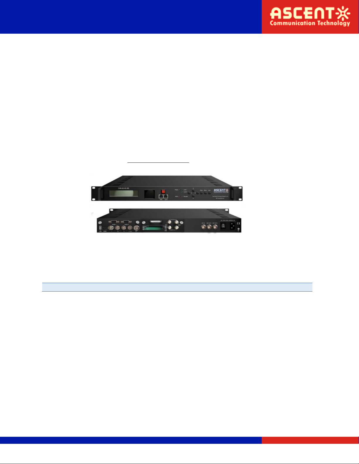
1.5 Appearance and Description ········································································································································ 6
1.6 System Connection Sample ·········································································································································· 8
Chapter 2. Installation Guide ..................................................................................................................................................... 9
2.1 Acquisition Check ························································································································································· 9
2.2 Installation Preparation ················································································································································ 9
2.3 Wire’s Connection ······················································································································································ 11
2.4 Signal Cable Connection ············································································································································· 11
Chapter 3. Operation ............................................................................................................................................................... 14
3.1 LCD Menu Class Tree ·················································································································································· 15
3.2 General Settings ························································································································································· 17
Chapter 4. Web-based NMS Management .............................................................................................................................. 28
4.1 Login··········································································································································································· 28
4.2 Operation ··································································································································································· 28
Chapter 5. Troubleshooting ..................................................................................................................................................... 45
Solutions Provider for FTTx, RFoG, and HFC www. ascentcomtec.com Page 3 of 46

IRD1560 Decoder User Manual
IRD1560 DVB-S2 HD IRD is ASCENT’s all-in-one device which integrates demodulation, de-
scrambler, remux and decoding in one case to convert RF signals into audio/video
(CVBS/YPbPr/HDMI/SDI) output.
It is a 1-U case which supports 2 tuner inputs to receive signal from satellite. The two
CAMs/CIs accompanied can descramble the programs input from encrypted RF, ASI and IP.
The CAM requires NO unsightly external power cords, cables, or additional remote control
device.
Its pluggable structure design greatly facilitates the change of modules (demodulator or
decoder) as needed.
To meet customers’ various requirements, IRD1560 is also equipped with ASI and IP input for
remux, and output with 2 ASI ports and IP port.
Demodulation + descrambler +remux+ decoder modules in one box
2 DVB- S/S2Tuner inputs
1 ASI & 1 IP (UDP) input for remux
One CAM can decrypt multiple programs from Tuners/ASI/IP
One channel video output with various interface option (MPEG2/H.264)
Dual stereo audio output, or one Dolby Digital/Dolby Digital Plus (5.1) channel output
Support Dolby Digital/Dolby Digital Plus Decoding and passthrough
IP (1 MPTS & 8 SPTS) over UDP and RTP/RTSP output; ASI out
Support CC, Subtitle and Teletext
Support maximum 128 PID mapping per input
Pluggable and changeable demodulator and decoder modules
LCD display, Remote control and Firmware, web NMS management
Updates via web
Solutions Provider for FTTx, RFoG, and HFC www. ascentcomtec.com Page 4 of 46

IRD1560 Decoder User Manual
Input
2 × DVB-S/S2 RF, F type
1 × ASI input for re-mux, BNC interface
1 × IP input for re-mux (UDP)
Demodulating section
DVB-C
Standard
J.83A (DVB-C), J.83B, J.83C
Input Frequency
30 MHz ~ 1000 MHz
Constellation
16/32/64/128/256 QAM
DVB-T/T2
Input Frequency
30 MHz ~ 999.999 MHz
Bandwidth
6/7/8 M bandwidth
DVB-S
Input Frequency
950 ~ 2150 MHz
Symbol Rate
2 ~ 45 Msps
Signal Strength
-65 ~ -25 dBm
Constellation
1/2, 2/3, 3/4, 5/6, 7/8, QPSK
DVB-S2
Input Frequency
950 ~ 2150 MHz
Symbol Rate
Qpsk 1 ~ 45 Mbauds
8PSK 2 ~ 30 Mbauds
Code Rate
1/2, 3/5, 2/3, 3/4, 4/5, 5/6, 8/9, 9/10
Constellation
QPSK, 8PSK
Descrambling
CAM/CI Quantity
2
BISS Mode
Mode 1, Mode E;
Up to 120 Mbps
Output
IP Output
1 × MPTS & 8 × SPTS over UDP, RTP/RTSP.
100Base-T Ethernet interface (unicast / multicast)
2 × ASI
BNC interface, mirrored out
Decode Output
Video interface: 1 × CVBS/YPbPr/HDMI/SDI
Resolution: 480i, 480p, 576i, 576p, 720p, 1080i, 1080p
Video decode: MPEG-2; H.264
Audio interface; 2 × Stereo / 4 × Mono, HDMI, SDI
Audio decode: MPEG 1 Layer II, LC-AAC, HE-AAC, Dolby Digital AC3
Audio output mode: Left, Right, Stereo, 5.1 CH
System
Local Interface
LCD + control buttons
Remote Management
Web-server Management
Upgrade
USB, web management
General
Power Supply
AC 100V ~ 240V
Solutions Provider for FTTx, RFoG, and HFC www. ascentcomtec.com Page 5 of 46

IRD1560 Decoder User Manual
Dimensions
482 mm × 300 mm × 44.5 mm
Weight
3 kg
Operation Temperature
0 ~ 45°C
IP Output
Decoder
Module
ASI Output 1,2
Video
(CVBS/YPbPr/HDMI/SDI)
Audio 1: analog stereo or Dolby
Digital/Dolby Digital Plus 5.1 CH
MUX
IP
Tuner 2
ASI
CAM/CI 1
Tuner 1
CAM/CI 2 Audio 2: analog stereo
Front Panel Illustration:
1
LCD display for device control and configuration
2
Mini LCD TV for decoding monitor
3
Mini LCD TV power switch
4
NMS Port (for PC connection)
5
DATA Port (for IP stream input & output)
Solutions Provider for FTTx, RFoG, and HFC www. ascentcomtec.com Page 6 of 46

IRD1560 Decoder User Manual
6
Indicators Area (Lock 1&2: to indicate RF input signal lock status; Decoder: to
indicate the decoding status)
7
Up/Down/Left/Right Buttons
Enter Key
Menu Key
Lock Key
Rear Panel Illustration
1234589
67
10 11 12 13
Decoder Board
1
USB upgrade port
2
HDMI video/audio output
3
Component video output (YPbPr)
4
Composite video output (CVBS)
5
SDI video/audio output
6
Analog stereo audio out 1 (R/L)
7
Analog stereo audio out 2 (R/L)
8
CAMs /Smart card slots A & B
9
RF signal input and loop-through 1 & 2
Tuner Receiving
Board
10
ASI input Port for remux
11
ASI mirrored output ports
12
Power switch/Fuse/Socket
13
Grounding Wire
Solutions Provider for FTTx, RFoG, and HFC www. ascentcomtec.com Page 7 of 46

IRD1560 Decoder User Manual
Solutions Provider for FTTx, RFoG, and HFC www. ascentcomtec.com Page 8 of 46

IRD1560 Decoder User Manual
When user opens the package of the device, it is necessary to check items according to
packing list. Normally it should include the following items:
IRD1560 DVB-S2 HD IRD 1pcs
User’s Manual 1pcs
HDMI Cable 1pcs
YPbPr Cable 1pcs
CVBS Cable 1pcs
SDI Cable 1pcs
Audio adapt cables 2sets
Power Cord 1pcs
If any item is missing or mismatching with the list above, please contact our company.
When users install device, please follow the below steps. The details of installation will be
described at the rest part of this chapter. Users can also refer rear panel chart during the
installation.
The main content of this chapter including:
Checking the possible device missing or damage during the transportation
Preparing relevant environment for installation
Connecting signal cables
Connecting communication port with PC
Connecting
Grouding
Wire and
Power
Cord
Acquisition
Check Fixing
Device Setting
Parameter Running
Device
Connecting
Signal Wire
Solutions Provider for FTTx, RFoG, and HFC www. ascentcomtec.com Page 9 of 46

IRD1560 Decoder User Manual
Item
Requirement
Machine Hall Space
When user installs machine frame array in one machine hall, the distance
between 2 rows of machine frames should be 1.2 ~ 1.5 m and the
distance against wall should be no less than 0.8 m.
Machine Hall Floor
Electric isolation, dust free
Volume resistivity of ground anti-static material: 1×10⁷ ~ 1×10¹⁰Ω,
Grounding current limiting resistance: 1M (Floor bearing should be
greater than 450 kg/m2)
Environment Temperature
5~40°C (sustainable), 0~45°C (short time),
installing air-conditioning is recommended
Relative Humidity
20% ~ 80% sustainable 10% ~ 90% short time
Pressure
86 ~ 105 kPa
Door & Window
Installing rubber strip for sealing door-gaps and dual level glasses for
window
Wall
It can be covered with wallpaper, or brightness less paint.
Fire Protection
Fire alarm system and extinguisher
Power
Requiring device power, air-conditioning power and lighting power are
independent to each other. Device power requires AC power 100 ~ 240V
50 ~ 60Hz. Please carefully check before running.
All function modules’ good grounding is the basis of reliability and stability of devices. Also,
they are the most important guarantee of lightning arresting and interference rejection.
Therefore, the system must follow this rule.
Coaxial cables outer conductor and isolation layer should keep proper electric conducting with
the metal housing of device.
Grounding conductor must adopt copper conductor in order to reduce high frequency
impedance, and the grounding wire must be as thick and short as possible.
Users should make sure the 2 ends of grounding wire well electric conducted and be antirust.
It is prohibited to use any other device as part of grounding electric circuit
The area of the conduction between grounding wire and device’s frame should be no less than
25mm2.
All the machine frames should be connected with protective copper strip. The grounding wire
should be as short as possible and avoid circling. The area of the conduction between
grounding wire and grounding strip should be no less than 25mm2.
Solutions Provider for FTTx, RFoG, and HFC www. ascentcomtec.com Page 10 of 46

IRD1560 Decoder User Manual
Connecting the device’s grounding rod to frame’s grounding pole with copper wire.
Connecting Power Cord
User can insert one end into power supply socket, while insert the other end to AC power.
Connecting Grounding Wire
When the device solely connects to protective ground, it should adopt independent way, say,
share the same ground with other devices. When the device adopts united way, the
grounding resistance should be smaller than 1Ω.
Caution
Before connecting power cord to IRD1560, user should set the power switch to “OFF”.
The signal connections include the connection of input signal cable and the connection of
output signal cable. The details are as follows:
IP Input/output Cable Illustration:
Solutions Provider for FTTx, RFoG, and HFC www. ascentcomtec.com Page 11 of 46

IRD1560 Decoder User Manual
Tuner Cable Illustration:
ASI Input/output Cable Illustration:
Video & Audio output Cable Illustration: (for connection between the IRD and TV set or home
theater)
CVBS Cable YPbPr Cable
HDMI Cable SDI Cable
Solutions Provider for FTTx, RFoG, and HFC www. ascentcomtec.com Page 12 of 46

IRD1560 Decoder User Manual
Audio adapt cables Illustration: (for connection between the IRD and TV set)
Solutions Provider for FTTx, RFoG, and HFC www. ascentcomtec.com Page 13 of 46

IRD1560 Decoder User Manual
The front panel of IRD1560 DVB-S2 HD IRD is the user-operating interface and the equipment
can be conveniently operated and managed according to the procedures displayed on the
LCD:
Keyboard Function Description:
MENU: Cancel current entered value, resume previous setting; Return to previous menu.
ENTER: Activate the parameters which need modifications, or confirm the change after
modification.
LEFT/RIGHT: Choose and set the parameters.
UP/DOWN: Modify activated parameter or paging up/down when parameter is inactivated.
LOCK: Lock the screen/cancel the lock state. After pressing the lock key, the LCD will display
the current configuring state.
Solutions Provider for FTTx, RFoG, and HFC www. ascentcomtec.com Page 14 of 46

IRD1560 Decoder User Manual
Initializing
HD IRD
Bitrate: 70.865Mbps
Main Menu:
Status
Lock
Enter Menu
Status:
Alarm
Status:
Uptime
Main Menu:
Input Sets Input Sets
1: Tuner DVBS/S2
Input Sets
2: Tuner DVBS/S2
Up Down
Main Menu:
TS Config
TS Config:
TSID
TS Config:
ONID
TS Config:
ASI output select
TS output mode:
Mux
Tuner 1
Tuner 2
ASI
IP
ASI output select:
MPTS
SPTS 1
SPTS 8
Main Menu
CI Card CI Card:
Card A
CI Card:
Card B
1: Tuner DVBS/S2
Tuner Parameters
1: Tuner DVBS/S2
Mux Program
Tuner Parameters:
Satellite frequency
LNB frequency
Symbol rate
LNB voltage
22K
Signal Lock
Mux Program:
TS Lock
Parse Program
Select Program
Card A:
Max Birate
Input TS Mode
Card Error Check
Parse Program
Descramble Program
Rom Version
Card Status
Descramble Error
TS Config:
TS output mode
(Same content with ‘Tuner 1’above)
(Same content with ‘Card A’above)
IP Config:
Input IP
Input Port
Multicast
IGMP Snooping
Service IP
Input Sets
3: ASI 3 ASI:
TS Lock
Parse Program
Select Program
Input Sets
4: IP 4: IP
IP Config
4: IP
Mux Program Mux Program:
TS Lock
Parse Program
Select Program
TS Config:
TS output bitrate
Solutions Provider for FTTx, RFoG, and HFC www. ascentcomtec.com Page 15 of 46

IRD1560 Decoder User Manual
Main Menu:
System System:
Save Config
System:
Load Saved CFG
System:
Factory Reset
System:
LCD Time-out
System:
Lock Keyboard
System:
Product ID
System:
Language
Save Config?
Yes ►No
Load Saved CFG?
Yes ►No
Reset all sets?
Yes ►No
LCD Time-out
►30 s
Lock Keyboard
Yes ►No
xxxxxxxxxxxxxxxxx
xxxxxxxxx
Language
►English 中文
System:
Key Password Set Password
000000
Main Menu:
Network Network:
NMS IP
Network:
Subnet Mask
Network:
Gateway
Network:
MAC Address
Network:
Reset Password
NMS IP
192.168.0.136
Subnet Mask
255.255.255.0
Gateway
192.468.0.1
MAC Address
201212345678
Reset Password
Yes ►No
Network:
Web NMS Port Web NMS Port
80
Main Menu
Decoder Decoder:
Video Format
Audio Mode
Audio Select
Volume
Search Program
Program Select
Rom Version
Decoder Status
Main Menu:
IP Stream
IP Stream:
Output Protocol
IP Stream:
MPTS 1
IP Stream:
Gateway
MPTS 1:
Data Enable
Null PKT Filter
Output IP
Output Port
SPTS 1:
Data Enable
Null PKT Filter
Output IP
Output Port
Bitrate
IP Stream:
Service IP
IP Stream:
Subnet Mask
IP Stream:
SPTS 1
IP Stream:
SPTS 8 (SPTS 2-8 have the same submenus
with ‘SPTS 1’above)
System:
Version HD IRD
SW x.xx HW x.xx
Solutions Provider for FTTx, RFoG, and HFC www. ascentcomtec.com Page 16 of 46

IRD1560 Decoder User Manual
Switch on the device and after a few seconds’ initialization, it presents start-up pictures as
below:
HD IRD: Device’s name
Bitrate: xx.xxx MHz indicates the current effective bitrate multiplexed output.
Press LOCK key on the front panel to enter the main menu. The LCD will display the following
pages where user can configure the parameters for the device:
User could do all the settings according to the 8 directions displayed on the LCD. User can
press UP/DOWN buttons to specify menu item, and then press ENTER to enter the submenus
as below:
Alarm: The alarm indicator will turn on if there are no A/V signals inputting or outputting bit
rate overflows. User then can enter this menu to check the error type. Otherwise it shows the
‘system is normal’.
Uptime: It displays the working time duration of the device. It times upon power on.
Start up…
Start OK…
HD IRD
Bitrate: xx.xxx Mbps
Main menu
1 Status
2 Input Sets
3 CI Card
4 TS Config
5 Decoder
6 IP Stream
7 Network
8 System
Alarm
System is normal
Solutions Provider for FTTx, RFoG, and HFC www. ascentcomtec.com Page 17 of 46

IRD1560 Decoder User Manual
IRD1560 supports 2 tuners input, 1 ASI input and 1 IP stream input. Users can enter ‘Input
Sets’ to configure the tuner/IP parameters to receive the transport streams and select
programs to mux out. It displays as below:
Tuner DVBS/S2:
Press ENTER key to enter ‘1 Tuner DVBS/S2’ (or ‘2 Tuner DVBS/S2’), it displays as below:
Tuner Parameters:
Users can enter this menu to configure the tuner parameters separately to receive the tuner
programs.
Tuner Parameters:
Satellite frequency
LNB frequency
Symbol rate
LNB Voltage
22K
Signal Lock
Uptime
1 Day(s) 03:30:02
1 Tuner DVBS/S2
Tuner Parameters
Mux Program
Input Sets
1 Tuner DVBS/S2
2 Tuner DVBS/S2
3 ASI
4 IP
For checking signal status and quality etc.
Solutions Provider for FTTx, RFoG, and HFC www. ascentcomtec.com Page 18 of 46

IRD1560 Decoder User Manual
Mux Program:
Users can parse the Tuner input program list and select program(s) to mux out in this menu.
Note
Multiplexing operation can only take effect on condition that the “TS output mode” is
set to “Mux” under ‘TS Config’. (i.e.: TS Config
→
TS output mode
→
Mux)
ASI:
Users can parse ASI input programs and select program(s) to mux out under this menu. The
operating method is same with what explained above.
3: ASI
TS Lock
Parse Program
Select Program
Mux Program
TS Lock
Parse Program
Select Program
TS Locked
Bitrate: 4.040 Mbps
Searching Program
Get 7 Programs
For reading the input
bitrate
For reading the
number of programs
from Tuner 1 (or 2)
Mux Program (0/7)
1: CCTV 1X
‘1/7’ represents there are all 7 programs in the list and 1 program has been selected to mux out through ASI.
Mux Program (0/7)
1: CCTV 1 [←]
Mux Program (0/7)
1: CCTV 1 [→]
Mux Program (1/7)
1: CCTV 1
√
Process of selecting programs to
output through front panel:
[←]: to cancel program output;
[→]: to output the program
“√”: a symbol indicating the
corresponding program has been
selected to output;
“X”: a symbol indicating the
corresponding program has not
been selected to output
Press ENTER key
Press RIGHT/LEFT
key to shift arrow
Press ENTER key to
confirm
Solutions Provider for FTTx, RFoG, and HFC www. ascentcomtec.com Page 19 of 46

IRD1560 Decoder User Manual
CI Card
Card A
Card B
IP:
Press ENTER key to enter ‘4 IP’, it displays as below:
IP Config:
Users can enter this menu to configure IP parameters according to the IP source to receive the
IP programs.
Mux Program:
Users can parse the IP input program list and select programs to mux out in this menu. The
operating method is same with what explained above.
IRD1560 supports 2 CI cards (Card A & Card B) to descramble programs from either encrypted
RF, ASI or IP. Users can press ENTER key to enter ‘CI Card’ to configure the 2 cards respectively.
Press ENTER key to enter Card A (or Card B):
Mux Program
TS Lock
Parse Program
Select Program
Off, V2 and V3 Optional
4: IP
IP Config
Mux Program
IP Config
Input IP
Input Port
Multicast
IGMP Snooping
Service IP
Solutions Provider for FTTx, RFoG, and HFC www. ascentcomtec.com Page 20 of 46
Table of contents
Popular Media Converter manuals by other brands

Siko
Siko SG42 Translation of the original installation instructions

Extron electronics
Extron electronics mediaport 200 user guide

Extron electronics
Extron electronics DSC HD-HD user guide

MiLAN
MiLAN MIL-C2414 Series installation guide

Haivision
Haivision Makito HVS-ID-QS-MAKD-130 quick start guide

Brightlink
Brightlink BL-MOD-VW-6X20-4K user manual