ASCOM NUDM3-HE User manual
INSTALLATION GUIDE
Customizable Button Module
(NUDM3–HE)

Symbols
INSTALLATION GUIDE
Customizable Button Module (NUDM3–HE)
1 Symbols
Important Safety Information
The NUDM3–HE (NUDM3) Installation Guide contains important instructions when installing and maintaining
the NUDM3. To ensure a safe working environment during the installation and operation of the NUDM3, the
following safety symbols appear throughout this document to indicate dangerous conditions and important
safety instructions.
Caution: Use extreme caution and follow instructions carefully.
Pay particular attention to statements referred to by a note.
1TD 93506EN / 02 March 2022 / Ver. A

INSTALLATION GUIDE
Customizable Button Module (NUDM3–HE) Description
2 Description
The Customizable button module is a wall-mounted device that is suitable for general room applications.
The module connects to an active room bus and is typically mounted near a door.
Packing list:
• 1 x Customizable button module NUDM3–HE
Available Accessories
Accessories Surface Mounting Spacer, EU (P/N NUSP1-HE)
Installation Frame 1U, EU (P/N NUF1U-HE)
Installation Frame 2U, EU (P/N NUF2U-HE)
Installation Frame 3U, EU (P/N NUF3U-HE)
Button Insert Kit EU (P/N NUCBK-HE)
Button Insert Kit UK (P/N NUCBK-HK)
Accessories are not included and must be ordered separately.
TD 93506EN / 02 March 2022 / Ver. A 2
Mounting
INSTALLATION GUIDE
Customizable Button Module (NUDM3–HE)
3 Mo nting
The base of the module mounts directly onto flat walls or ceiling surfaces.
Caution: To prevent a fire hazard because of dust buildup inside the module, regular
inspection and/or cleaning of the module is required.
Take proper measures to avoid spreading dust and other particles when applying
maintenance to a module that is mounted inside a clinical area.
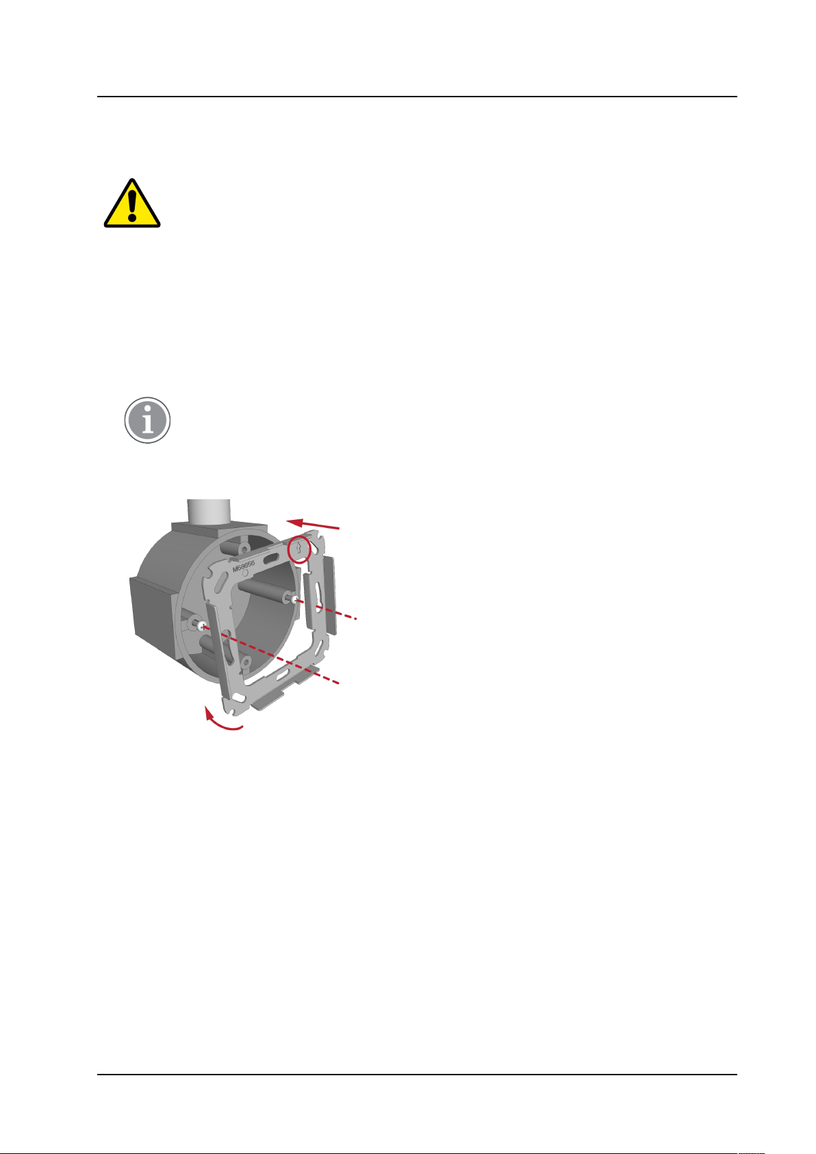
3.1 Mo nt the NUDM3 onto a backbox
To attach an adapter to a backbox:
1. For EU-style or UK-style backboxes, loosen the screws from the backbox so that approximately 5mm
extend out from the backbox and the heads of the screws can pass through the keyhole slots on the
adapter plate.
The screw distance for the backboxes must be 60mm (2.36 in.).
2. Place the adapter (with the arrow facing up, see below) over the backbox and ensure that it is level,
and then tighten the screws.
3.2 Mo nt the NUDM3 onto a spacer
To attach an adapter to a spacer (NUSP1–HE):
1. Place the spacer against a flat wall and orient it so that “TOP” (printed on the inside of the spacer) is
pointing up and that the spacer is level. Use a leveling device to check, if necessary.
3 TD 93506EN / 02 March 2022 / Ver. A

INSTALLATION GUIDE
Customizable Button Module (NUDM3–HE) Mounting
2. Using the spacer as a template, mark two holes for the screws using the outer fitting holes located in
the corners of the spacer.
3. Remove the spacer and drill screw holes for the screws that will be used, such as wood, concrete, or
drywall screws, or screws with anchors.
4. Remove the knockouts in the spacer for the cable wires.
5. Place the spacer over the holes, insert the screws, and then tighten.
6. Place the adapter over the spacer ensuring that it fits inside the spacer’s housing.
7. Insert the screws though the adapter plate and into the spacer, and then tighten the screws.
8. Pull the connection cables through the knockout holes.
TD 93506EN / 02 March 2022 / Ver. A 4
Module Connectors
INSTALLATION GUIDE
Customizable Button Module (NUDM3–HE)
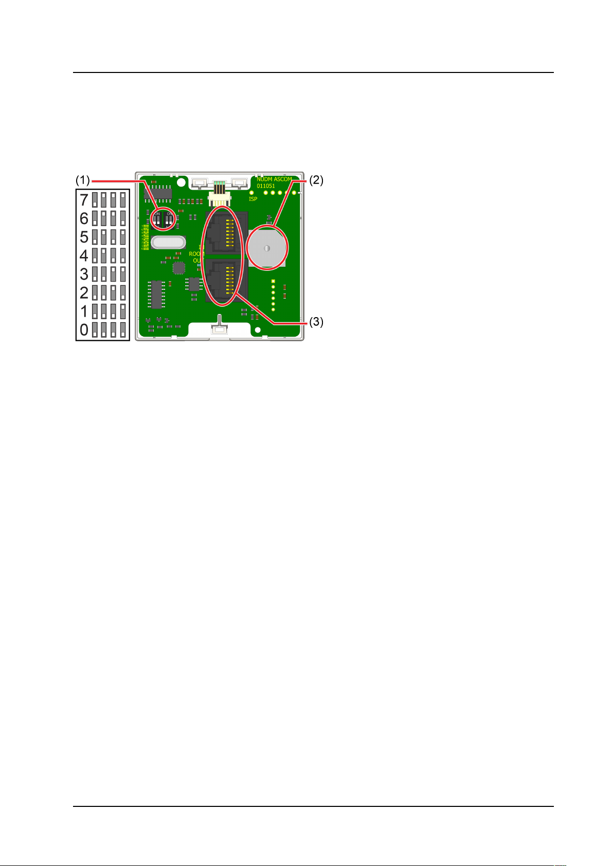
4 Mod le Connectors
The module includes two RJ45 jacks for room bus connections, a buzzer, and DIP switches for room bus
addressing.
Figure 1. Module Connections
Legend
1. DIP switches for room bus addressing
2. Buzzer
3. 2 x RJ45 connections to room bus
4.1 Setting the Room B s Address
The room bus address is a unique number assigned to a room module when modules of the same type are
attached to the room bus.
If you do not use DIP switches to set the room bus address, be sure all the DIP switches are in the OFF
position on the back of the module.
To set the DIP switches:
1. Set the DIP switches for the correct room bus address.
2. Using a small screwdriver, gently slide the switch up for “ON” or slide it down for “OFF”.
5 TD 93506EN / 02 March 2022 / Ver. A
INSTALLATION GUIDE
Customizable Button Module (NUDM3–HE) Mount the module
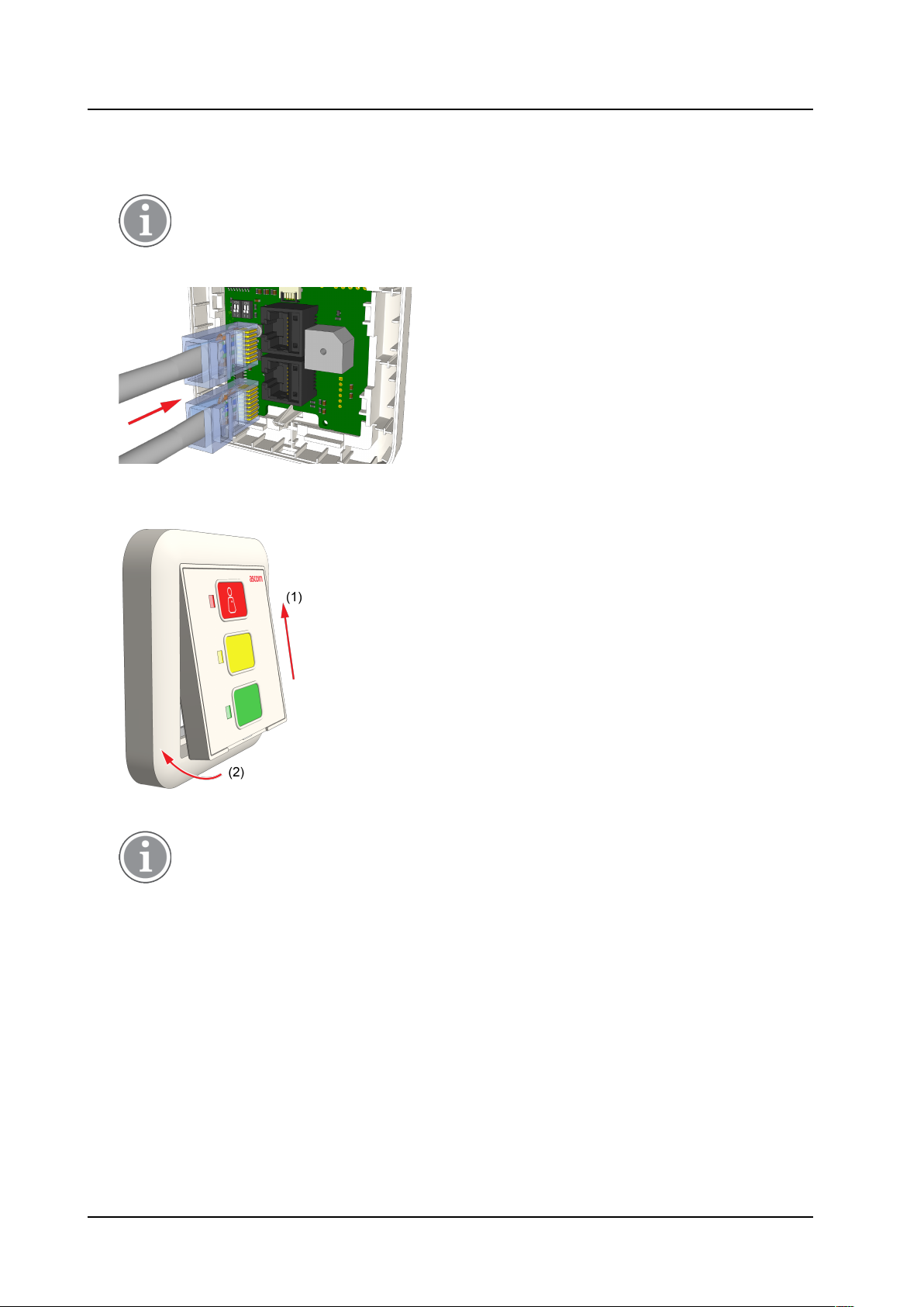
5 Mo nt the mod le
1. Pull the room buses through the adapter plate and the frame.
See 7 Terminating the Room Bus RJ45 Connectors, page 8.
2. Insert the room buses into the RJ45 connectors on the rear side of the NUDM3.
3. Place the frame with the module over the adapter and insert the top of the module first into the adapter
(item 1), and then click the bottom of the module into the adapter (item 2).
4. Perform a test and verify that the LEDs function correctly.
Only in a correctly configured system will a call or presence generate an alert on display
devices such as corridor lamps.
TD 93506EN / 02 March 2022 / Ver. A 6

Removing the module
INSTALLATION GUIDE
Customizable Button Module (NUDM3–HE)
6 Removing the mod le
Removal of the NUDM3 from wall or ceiling.
1. Remove the module:
• Insert a small flat tipped screwdriver into the hole on the bottom of the frame (item 1).
• Push the screwdriver up until the module pops out (item 2).
Caution: Do not insert the screwdriver into the bottom corner of the frame as this may
damage the frame or module.
It may be necessary to wiggle the screwdriver a bit for the module to come forward.
2. Pull the module gently away from the base. The module is still connected to the room bus.
3. Disconnect the room bus connectors from the rear of the module.
7TD 93506EN / 02 March 2022 / Ver. A

INSTALLATION GUIDE
Customizable Button Module (NUDM3–HE) Terminating the Room Bus RJ45 Connectors
7 Terminating the Room B s RJ45 Connectors
The NUDM3 includes two active room bus RJ45 sockets. Crimp the RJ45 connector(s) to the room bus
cable(s) using the Ethernet T-568B termination color scheme. The following figure shows the correct pinout
for terminating the active room bus cables.
RJ45 connector for active room b s cable
For easy mounting of the RJ45 connector, use Easy RJ45 connectors that allow feeding excess wire length
through the connector. When crimping, the excess wire length will be cut automatically.
(Easy) RJ45 connectors are not included and must be ordered separately.
Easy RJ45 connectors require a dedicated crimping tool (not included) that includes a cutting
mechanism to cut the excess wire when crimping the connector on the cable.
RJ45 Connector on Cat 6/7 Cables
Caution: Cat 6/7 cables may be too stiff to handle using the normal terminating procedure,
which can result in putting to much stress onto the switch module when it is mounted onto
the backbox.
Therefore remove an appropriate portion (1) of up to 15cm (6in.) of the outer jacket before
crimping the RJ45 connector onto the Cat 6/7 cable.
Note that the individual twisting of the wire pairs should remain intact up to the RJ45
connector.
TD 93506EN / 02 March 2022 / Ver. A 8

Replacing the button insert
INSTALLATION GUIDE
Customizable Button Module (NUDM3–HE)
8 Replacing the b tton insert
1. Remove current button insert by gently pulling the small tab at the lower end of the insert with a small
pair of pliers.
2. Insert a new button insert from the lower end of the module. Make sure the insert fits completely in the
membrane.
The button insert shall be water resistant.
3. Check that all of the button LEDs are visible.
Perform a test to verify that all LEDs work properly.
9 TD 93506EN / 02 March 2022 / Ver. A
Other manuals for NUDM3-HE
1
Table of contents
Other ASCOM Control Unit manuals


Popular Control Unit manuals by other brands

Festo
Festo Compact Performance CP-FB6-E Brief description

Elo TouchSystems
Elo TouchSystems DMS-SA19P-EXTME Quick installation guide

JS Automation
JS Automation MPC3034A user manual

JAUDT
JAUDT SW GII 6406 Series Translation of the original operating instructions

Spektrum
Spektrum Air Module System manual

BOC Edwards
BOC Edwards Q Series instruction manual

KHADAS
KHADAS BT Magic quick start

Etherma
Etherma eNEXHO-IL Assembly and operating instructions

PMFoundations
PMFoundations Attenuverter Assembly guide

GEA
GEA VARIVENT Operating instruction

Walther Systemtechnik
Walther Systemtechnik VMS-05 Assembly instructions

Altronix
Altronix LINQ8PD Installation and programming manual


