ASCOM T942PX User manual

1996 11 06 1
Installation Guide
PBX Interface T942PX TD 91012GB
PBX Interface T942PX - Installation Guide
T942PX is an interface unit between the teleCOURIER 900 paging system and a telephone exchange,
PBX (Private Branch Exchange). In some cases the T942PX is used to connect a telephone as control
instrument. The PX unit may be connected to an extension or to a trunk line. When connected to a
trunk line it detects and generates both dial pulses and DTMF tone signals. When connected to an
extension it detects and generates DTMF tone signals and generates dial pulses.
E & M signaling according to ”ESPA standard interface recommendation 4.4.3” is also possible. If
speech is used in the system, speech module T941SM is included.
A FLASH PROM in T942PX enables remote programming of the program and parameters.
Note: T942PX is not intended for connection to public telephone networks.
1. General
Supply voltage: 12,5 Vdc ± 10%
Current consumption: Max 0,5 A
Delivery includes:
• T942PX
• Modular bus cabling
• If the T942PX is to be used in a speech installa-
tion, speech module T941SM is mounted on the
T942PX PC board and installation guide
TD 90648GB is included in the delivery.
It is possible to order from your dealer package
T942PX-2 art. no 541175. In addition to the above
the delivery includes the following items:
• Power supply Mascot 8311, 42 Vac
• Telephone wall socket
• Telephone (Respons)
Tools etc. required:
• 2 mm drill
• Screwdriver
• Cutting pliers
• Screws for installation
• Multimeter
• (Oscilloscope)
2. Installation
T942PX should be placed in a dry environment with
a temperature of 0 to +40ºC. The unit can be
connected together with other units in the
teleCOURIER 900 system, either via modular bus
cabling or via twisted-pairs (see points 8, 9, and 10).
To replace the PC board, see point 18.
The second drawing at left shows dimensions for
installing the T942PX.
Use a screwdriver or similar to release the cover by
applying a light pressure to the two snap-catches (1)
and remove the cover (2).
2
1
1
9 9
275
56,5
188,5
65 130
112
Dimensions (H x W x D)
275 x 130 x 60 mm
Note:
To facilitate service after the unit is installed,
we recommend a free space of about 50 mm
above and 150 mm below the unit.
21996 11 06
Installation Guide
PBX Interface T942PX TD 91012GB
ICO1 ICO5
3
1
21
J08
J06
J03
SWO1
SW02
LEDO2
J01 J02
S03
J05
S05
J04A
J04B
S01 S02
1
6
IC16
1 12
21
J09
S04
S09
J07
S10
S06
S07 S08
IC02
S12 S16
S18 S17
S11
S13
S19
S15
S14
LEDO7
S20
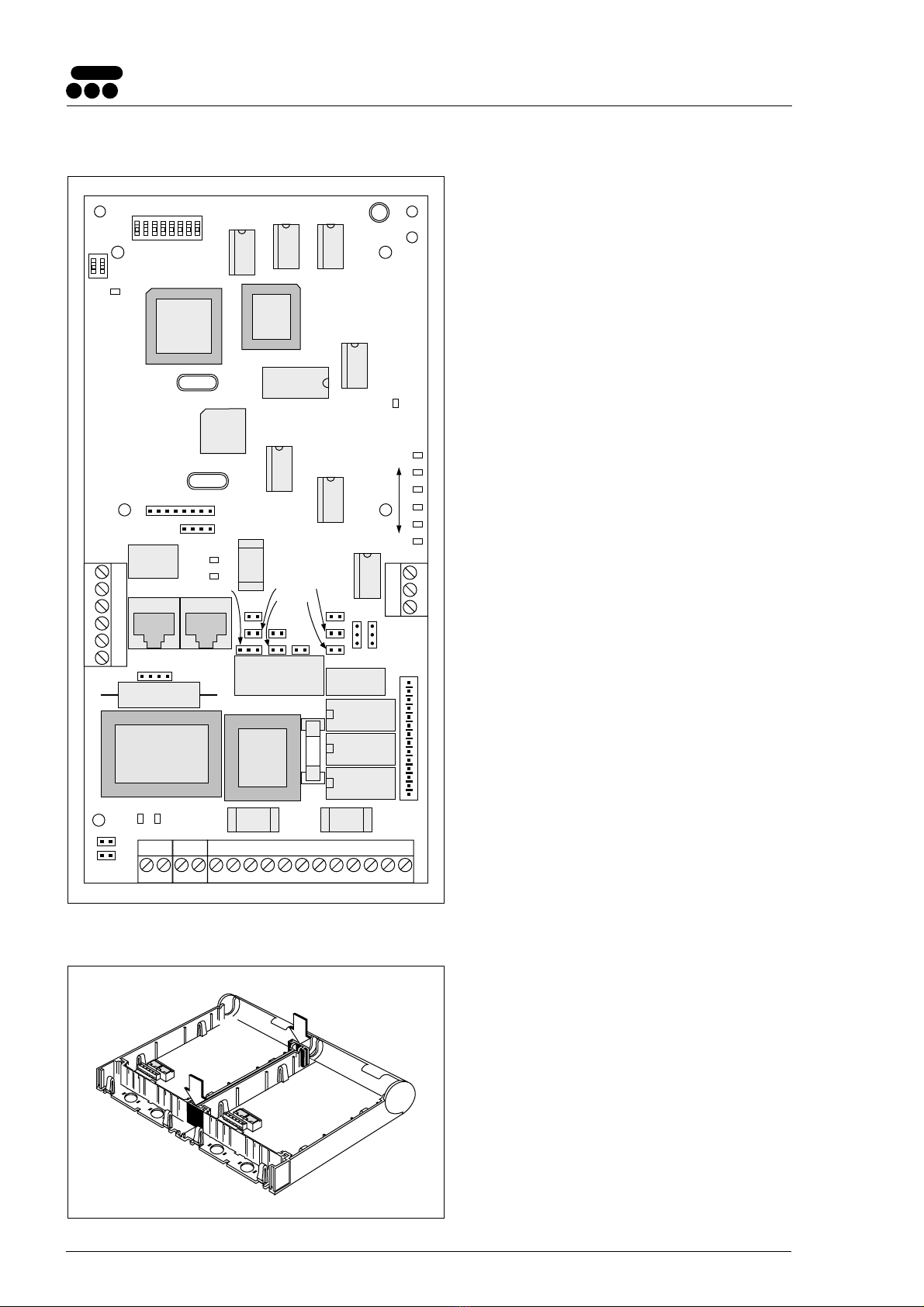
3. Screw Connectors etc. for Installation
J01, J02: Modular bus cabling for connection of
data buses.
J03: Supply voltage. Also used for connection
of A, B, C, or D bus when modular bus
cabling is not used.
J04A, J04B: For T941SM speech module.
J05: For audio lines, E-line, M-line, and if
needed external power.
J06: Power supply for ring signals, if used.
J07: For parallel connected telephone.
J08: For remote pagings.
J09: For voice module T941VM.
S01: Jumper points that must be soldered
together when PBX A345 with circuit
board TPC70 is used.
S02: Jumper points that must be soldered
together when T942PX is to detect
pulses and external 48 V.
S03: Not used.
S04, S05: Jumpers, for selection of A or B bus.
S06: Jumper, used to select trunk or
extension line.
S07, S08: Jumpers, drilled if ring signals are used.
S09, S10: Jumpers for adapting to different supply
voltages.
S11, S12, Jumpers for selection of 2-wire and
S13, S14: 4-wire speech/audio line connections.
S15, S16, S17: Jumpers for decadic pulsing.
S18, S19: Jumpers for impedance matching.
S20: Jumper points that must be soldered
together to enable use of software
program S941PX. See point 12.
LED01: Function indicator.
LED02: Dial tone indicator.
LED03: Indicates that a parallel connected tel-
ephone connected to T942PX, is in use.
LED04: Indicates received ring signal/impulse.
LED05: Indicates that relay for E-signal/decadic
pulsing is actuated.
LED06: Indicates that line relay is actuated.
LED07: Indicates that dial tone is being sent out.
SW01: Address switch.
SW02: Switch, section 1 selects trunk or exten-
sion line. Section 2 must be set to OFF.
IC05: FLASH PROM
4. Installation Together With Other 900
Units
1. Remove upper and lower covers. The lower
rectangular pieces are used to fasten units to
each other (1).
2. Fasten the unit with three screws, see the
illustration on page 1.
1
1

1996 11 06 3
Installation Guide
PBX Interface T942PX TD 91012GB
5. Addressing
Select the proper address by setting address selector
switch SW01 (see the document System Installation,
under "Addressing"). The address must not be 00
nor the same as any other 900 unit address.
SW01
ON
81
OFF
R87 S04
R88 S05
6. Selection of A or B Bus
A bus is normally used. To use B bus: remove the
0-ohm resistors R87, R88 from the PC board and
solder together jumper points S04 and S05.
(See drawing above.)
7. Wiring Runs
The plastic partition (shaded in the drawing) is scored
to facilitate breaking at convenient intervals.
1 2 3 4 5 6
1
2
1
1. Use pliers to break off a suitable section.
2. Run the wiring out through the partition.
Wiring can be run three ways from the unit:
• Remove the rectangular pieces and run the
cabling out through the side (1).
2
1
2
3
1
3
• Break off sections at short side of case and run
the cabling downwards (2).
• Run the cabling through the round holes at the
bottom of the case (3)
Secure the wiring with cable straps.
8. Connecting Supply Voltage and Buses
1. Supply voltage is connected to screw 1 and 2 of
screw connector J03. (See the document “System
Installation”, under “Supply Voltage”).
2. Connect modular bus cabling to J01 and J02
(1 in drawing at below left),
and/or
A or B bus to J03 screw 5 and 6
(dwg below and 2 in drawing at left).
NOTE: The data lines are polarized. Use only
twisted-pairs for two-wire connections!
J03
4
5 BUS 1
6 BUS 2
3
1 +12V
2 GND
Supply voltage in
Supply voltage out
A or B bus

41996 11 06
Installation Guide
PBX Interface T942PX TD 91012GB
9. Connection of PBX, External Power (if
necessary), and Remote Paging
Connect external wiring to screw connector J05
as shown in the drawing at left:
1. Connect audio line to J05-4 and 5.
(Audio out for 4-wire connection)
2. If the register recall signal (method 2 under
point 15) is used, connect the telephone
ground to screw 6.
3. If a 4-wire speech/audio line is used, the second
twisted pair is connected to J05-7 and 8.
(See point 13.) (Audio in, T941SM is required)
4. If external power is needed, connect it to
screws 1 and 2. Observe polarity!
5. If E & M signalling is used make connections
to J05-2, 3, 9, 10 and 11.
6. Remote start of pre-programmable personal
paging 1 and 2 are connected to J08-1 and 3,
and J08 2 and 3, respectively.
Selection of Installation Alternatives
The table at left is read horizontally and shows
five installation alternatives for connection to a
PBX:
S06, S09, S10, and SW02 (section 1) are used to
select the desired installation alternative. SW02 is
an ordinary toggle switch. S06, S09, and S10 are
special connectors and the pins on these connec-
tors are jumpered as required according to the
table by using special jumper plugs.
External 12 Vdc supply voltage can be taken from
J03 by connecting J03-1 to J05-2 and J03-2 to
J05-1. This is used only when a telephone that
operates on 12 Vdc is connected directly to the
T942PX.
The following example is for installation
alternative 2:
• Jumper S06 pins 2-3 and 4-5 with special
jumper plugs.
• Jumper S09 pins 1-2 with special jumper plug.
• Set section 1 of SW02 to OFF.
No jumper plug on S10.
• Connect external supply voltage, 24 Vdc to
J05-1 (negative) and J05-2 (positive).
J05
4 a
5 b
6 EARTH
3 M
1 Ext –
2 Ext +
10 E-Relay
11
12
9
7 4W
8 E & M
External voltage 12, 24, or 48 Vdc
PBX M signal in
Audio in/out (a and b line, 2-wire)
Audio out (a and b line, 4-wire)
GND (register recall)
Audio in (4-wire)
PBX E signal out
PBX E signal out, inverted
PBX E signal in
1
2
3
trunk line
trunk line
trunk line
S10
2-3, 4-5
2-3, 4-5
2-3, 4-5 NC
S06 S09
1-2 1-2
1-2 NC
Yes, 12 V
Yes, 24 V
Yes, 48 V NC
SW02
section 1
OFF
OFF
OFF
4extension 1-2, 3-4 NCNo NC ON
3-4 NC NC OFF
5E & M signalling
according to ESPA
Standard Interface
Recommendation 4.4.3
Inst.
alt.
Audio line
screw 4, 5
External
voltage
screw 1, 2
NC = Not connected
Installation alternatives 1–4 are not polarized.
For installation alternative 5, connections to
the PBX de
p
end on the t
yp
e of exchan
g
e.
Remote start 1 and 2 are CMOS inputs.
The inputs are activated when grounded, i.e.
when contacts close a paging is generated
J08
3 GND
1 Remote paging 1
2 Remote paging 2

1996 11 06 5
Installation Guide
PBX Interface T942PX TD 91012GB
T942PX (J05)
PBX
1
2
3
4
5
6
7
8
9
10
11
12
10. Paging from Mobile Unit to Base (PBX)
To initiate pagings from a mobile unit via PBX to a
predetermined telephone (“hot line”) the following
is necessary:
1. Check that the PBX is programmed for “hot line”.
2. Connect and set jumpers according to installation
alternative 4 (see table “Selection of Installation
Alternatives” on page 4).
11. PagingfromMobileUnittoBase(Telephone)
To initiate pagings from a mobile unit to a base
telephone, the following is necessary:
1. Connect and set jumpers according to installation
alternative 1 (see table “Selection of Installation
Alternatives” on page 4).
2. Connect the audio line (telephone wall socket)
to J05 screws 4 and 5 as shown in the drawing
at left:
• For telephone bell ringing, break the connec-
tions on S07 and S08 by drilling as shown in the
drawing at left:
Check that the connections are broken.
Connect a 42 Vac Mascot 8311 power supply
to J06 (can be ordered from your dealer) .
• If a diavox telephone is used, replace the
capacitor on the bell with a 0,15 µF/250 V
capacitor (diavox units ordered from your dealer
are delivered with correct capacitor).
12. Jumpering for Software Program S941PX
To enable use of software program S941PX remove
0-ohm resistor R92 and solder together jumper
points S20 (see drawing at left).
Note that software program S941PX affects
the function of LED01 (orange indication is
replaced by green, see point 17. Installation
Test Procedure).
T942PX (J05)
1
2
3
4
5
6
7
8
9
10
11
12
R92 S20
42 Vac
J06
S07 S08
drill out

61996 11 06
Installation Guide
PBX Interface T942PX TD 91012GB
17. Installation Test Procedure
1. Check that section 2 of switch SW02 is set to OFF.
2. Energize the teleCOURIER 900 system. Function
indicator LED01 on the T942PX unit should light
red for about 1 second and then go over to a
flashing orange.
If it continues to indicate with a steady red check
that supply voltage is 12,5 Vdc ± 10%.
Flashing red indicates a program fault.
Function indicator
3. If the T942PX is connected to a central, the
indicator should show a steady green indication
within 90 seconds.
If the indicator continues to blink orange, check:
• polarity
• connections on T942PX unit
• T942PX unit is properly addressed
If everything seems to be in OK but the function
indicator still blinks, the fault is probably located
outside the T942PX. Check the other 900 units
according to doc. no TD 90227GB, “System
Installation teleCOURIER 900”, or contact your
dealer.
4. Initiate a paging from a telephone connected to
the PBX.
• If the paging is transmitted the installation is
correct. Replace the cover and continue with
point 5 below.
• If the paging is not transmitted, perform test
of the applicable installation alternative below
(see point 17a - 17e). Then replace the cover
and continue with point 5 below.
5. When all other units are installed, perform the
system test described in “System Installation
teleCOURIER 900”, document no. TD 90227GB.
13. Selection of 2-Wire or 4-Wire
Speech/Audio Line Connection
Normally 2-wire speech/audio line connection is used.
• 2-Wire Speech/Audio Line Connection:
One twisted pair, connected to J05-4 and 5, is used
for sending and receiving speech and DTMF tones.
Set jumpers S12 and S13 to 1-2, and S14 to 2-3.
S11 is not to be jumpered.
• 4-Wire Speech/Audio Line Connection:
One twisted pair, connected to J05-4 and 5, is used
for sending speech and DTMF tones.
A second twisted pair, connected to J05-7 and 8, is
used for receiving speech and DTMF tones.
Set jumpers S11 and S14 to 1-2.
S12 and S13 are not to be jumpered.
Note: Speech module T941SM is always
required when the 4-wire speech/audio
line connection is used.
14. Impedance Matching
T942PX input impedance is set with jumpers S18 and
S19.
For the normal setting (600 ohm) S18 is set to 1-2
and S19 is not jumpered.
When the impedance is complex, S19 is set to 1-2
and S18 is not jumpered
15. Register Recall Signal
T942PX produces the register recall signal,
(R-button on telephone), according to one of the
following methods which is selected by a software
parameter (method 1 is default):
Method 1. Audio line dc-loop is broken for a
certain time.
Method 2: The audio line connected to J05-4 is
short circuited to J05-6.
If method 2 is used J05-6 must be connected to
telephone ground.
16. Decadic Pulsing (Dial Pulses)
If T942PX is connected to an extension (installation
alternative 4 in table on page 4) and decadic pulsing
is used, jumpers S15, S16, and S17 must be set to
1-2. In all other cases S15, S16, and S17 are not to
be jumpered.

1996 11 06 7
Installation Guide
PBX Interface T942PX TD 91012GB
17a. Test of Installation Alternatives 1-3
1. Disconnect the PBX wires on J05-4 and J05-5 and
connect a telephone to the screws instead.
2. Lift the receiver and wait for the dial tone.
3. Initiate a paging from the telephone. If the
paging is transmitted, the T942PX is working
properly, and the fault must be in either the PBX
or the wiring to it.
If the paging is not transmitted, check the
T942PX address and the installation jumpers.
4. Disconnect the telephone and reconnect the PBX.
5. Return to point 17 above.
17b. Test of Installation Alternative 4
1. Check the T942PX address and the installation
jumpers.
2. Initiate a paging. If the paging is not transmitted
contact your dealer.
3. Return to point 17 above.
17c. Test of Installation Alternative 5
1. Change settings and jumpers to installation
alternative 1 (see table on page 4).
2. Disconnect the PBX wires on J05-4 and J05-5 and
connect a telephone to the screws instead.
3. Lift the receiver and wait for the dial tone.
4. Initiate a paging from the telephone. If the
paging is transmitted the T942PX is working
properly, and the fault must be in either the PBX
or the wiring to it.
If the paging is not transmitted, check the
T942PX address and the installation jumpers.
5. Disconnect the telephone and reconnect the PBX
according to installation alternative 5 (see table
on page 4).
6. Return to point 17 above.
17d. Test of Paging from Mobile Unit to Base (PBX)
1. See “Test of Installation Alternative 4”.
2. Return to point 17 above.
17e. Test of Paging from Mobile Unit to Base
(Telephone)
1. See “Test of Installation Alternatives 1-3”.
2. Return to point 17 above.
18. PC Board Replacement
1. Deenergize the unit.
2. Remove the cover.
3. Lift off the connectors from the PC board.
1
1
3
2
1
1
4. Press the four holding clips (1) to release the PC
board.
5. Install the new PC board in the case and make
sure the board clicks into position.
6. Set all switches and jumpers as they were on the
original circuit board and replace the connectors.
7. Check installation according to point 17,
“Installation Test Procedure”.


