DF18060701
This option allows Hydro Unit to be controlled either Setting temperatures or Capacity.
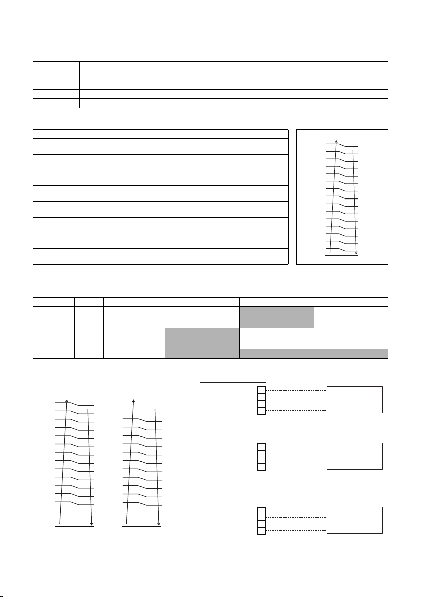
Control of Setting temperature
• DN 680 is set to “1”.
• Set the input method for each setting temperature.
• Allocate the temperature of 0 to 10 V, and also set its resolution.
( )*1: AIO-Type ( )*2: HWT-110
*3: In actual operation, it would be restricted by DN setting which related to water / room temperature control.
Capacity direct control
• DN 680 is set to “2, 3 or 4”.
DN Item Selectable value (Input from)
681 Hot water setting temperature. 0: Not use AI 1: AI 1 2: AI 2 3: AI 3
682 Zone 1 setting temperature for heating. 0: Not use AI 1: AI 1 2: AI 2 3: AI 3
683 Zone 2 setting temperature for heating. 0: Not use AI 1: AI 1 2: AI 2 3: AI 3
684 Zone 1 setting temperature for cooling. 0: Not use AI 1: AI 1 2: AI 2 3: AI 3
DN Item Selectable value
685 Upper limit of hot water setting temp.
(at voltage level 16)
40 to 80 (65)*1
Default: 65°C
689 Resolution of hot water setting temp.
(Value per voltage level)
1 to 5
Default: 5°C
686 *3 Upper limit of Zone 1 setting temperature for heating
(at voltage level 16)
20 to 55 (65)*2
Default: 55°C
68A Resolution of Zone 1 setting temperature for heating
(Value per voltage level)
1 to 5
Default: 3°C
687 *3 Upper limit of Zone 2 setting temperature for heating
(at voltage level 16)
20 to 55 (65)*2
Default: 55°C
68B Resolution of Zone 2 setting temperature for heating
(Value per voltage level)
1 to 5
Default: 3°C
688 *3 Upper limit of Zone 1 setting temperature for cooling
(at voltage level 16)
7 to 29
Default: 20°C
68C Resolution of Zone 1 setting temperature for cooling
(Value per voltage level)
1 to 5
Default: 1°C
DN [680] 0 1 2 3 4
AI 1
Not use
Control of Setting
temperature
Enter settings from DN
681 to 684
Capacity direct control of
HP operation for Heating /
Cooling mode
Not use
Capacity direct control of
HP operation for Heating /
Cooling mode
AI 2 Not use
Capacity direct control of
HP operation for Hot water
mode
Capacity direct control of
HP operation for Hot water
mode
AI 3 Not use Not use Not use
• DN 680 = 2
Analog input enable only for Heating or cooling mode.
• DN 680 = 3
Analog input enable only for Hot water mode.
• DN 680 = 4
Analog input enable for Heating / Cooling and Hot water
mode.
10.0
16
1
3
1.4
0.8
0.6
1.2
2
3.2 3.0
5
2.6 2.4
4
2.0 1.8
3.6
6
9
5.0 4.8
8
4.4 4.2
7
3.8
6.0
10
6.8 6.6
11
6.2
5.6 5.4
13
7.4 7.2
12
9.2
9.0
15
8.6 8.4
14
8.0 7.8
[V] Voltage level
(Upper limit)
Analog input
10.0 10.0
%
0.0 0.0
2.0 1.8
1. 4
0. 8
5.6 5.4
%
5.0 4.8
%
4.4 4.2
%
3.8 3.6
%
3.2 3.0
%
2.6 2.4
%
%
8.0 7.8
%
7.4 7.2
%
6.8 6.6
%
6.2 6.0
%
0. 8
0. 6
4.4 4.2
3.8 3.6
3.2 3.0
2.6
%
%
%
2.0
6.6
6.2 6.0
5.6 5.4
5.0
%
%
%
6.8
9.2
9.0
8.6 8.4
8.0 7.8
7.4
%
1.8
1. 4
1. 2
2.4
%%
%
%
4.8
7.2
%
%
%
[V]
Heating / Hot water
Capacity
Demand
Analog input
No
operation
[V]
Cooling
Capacity
Demand
Analog input
No
operation
AI 1 DC0-10 V (+)
Common (-)
0-10 V interface
PCB 1
2
3
4
DDC
(procured locally)
CN5
AI 2 DC0-10 V (+)
Common (-)
0-10 V interface
PCB 1
2
3
4
DDC
(procured locally)
CN5
AI 1 DC0-10 V (+)
Common (-)
0-10 V interface
PCB 1
2
3
4
DDC
(procured locally)
CN5
AI 2 DC0-10 V (+)


