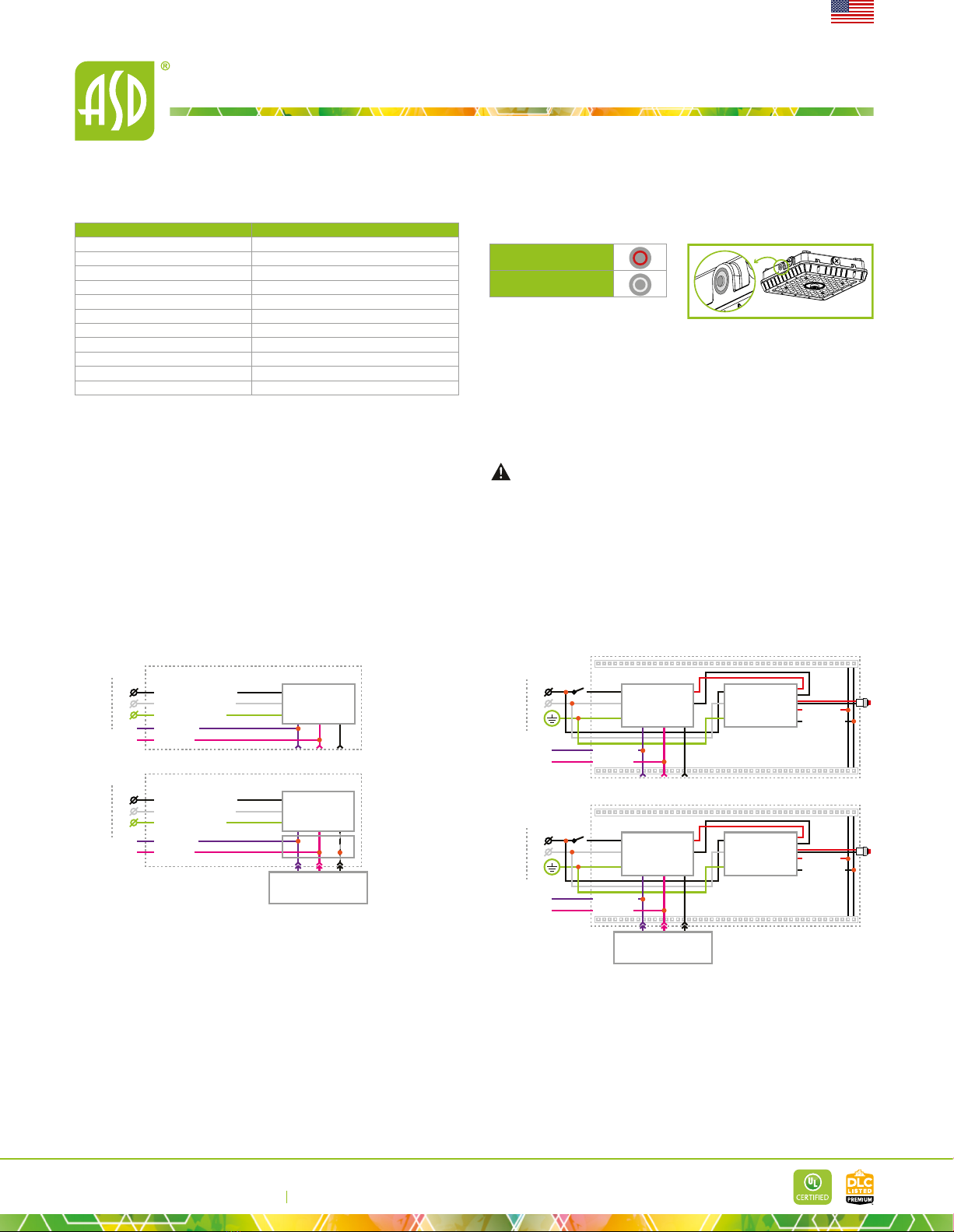
ASD ASD-CAN07A-45DAC-WH User manual

E-mail: [email protected]
ASD LIGHTING CORP
Web site: www.asd-lighting.com
For most up-to-date spec sheets please refer to asd-lighting.com
English
Q-BASE LED LOW-PROFILE CANOPY
DESIGN - Q-BASE LED LOW-PROFILE CANOPY has a built-in motion
sensor base, allowing you to install the microwave motion or PIR sensor. Die-cast
aluminum housing with excellent heat dissipation along with an anti-glare PC
lens provides many years of use. It is equipped with a removable hinge door for
quick and easy wiring. It is designed to operate on 120-277V circuits with a 1-10V
dimmable driver.
BATTERY BACK-UP - The built-in battery back-up provide 90 minutes of
power in case of emergency.
COLOR SELECTABLE - You can choose either a 3,000K warm white,
4,000K cool white or 5,000K daylight color temperature.
surges.
INSTALLATION
surface mounted or pole mounted. Perfect commercial or industrial solution for
parking garages, gas stations, stairwells, passageways, underpasses, and many
other applications.
ADVANTAGES - With calculated lifespan up to 150,000 hours, these
Catalog number
Notes
Type
Model Watts Voltage Dimmable Lumens CCT Finish Dimensions (LxWxH) Option
ASD-CAN07A-45DAC-WH 45W 120-277 V 1-10 V 6,230/6,916/6,900 lm 3CCT (3,000/4,000/5,000 K) White 10-9/16" x 9-13/16" x 2-15/16" -
ASD-CAN07A-45DAC-BK 45W 120-277 V 1-10 V 6,230/6,916/6,900 lm 3CCT (3,000/4,000/5,000 K) Black 10-9/16" x 9-13/16" x 2-15/16" -
ASD-CAN07A-70DAC-WH 70W 120-277 V 1-10 V 8,381/9,331/8,945 lm 3CCT (3,000/4,000/5,000 K) White 10-9/16" x 9-13/16" x 2-15/16" -
ASD-CAN07A-70DAC-BK 70W 120-277 V 1-10 V 8,381/9,331/8,945 lm 3CCT (3,000/4,000/5,000 K) Black 10-9/16" x 9-13/16" x 2-15/16" -
CAN07A-EM WITH BATTERY BACK-UP
ASD-CAN07A-45DAC-8EM-BK 45W 120-277 V 1-10 V 6,230/6,916/6,900 lm 3CCT (3,000/4,000/5,000 K) Black 10-9/16" x 9-13/16" x 2-15/16" 8W Battery back-up
HD09VR-MH Microwave motion sensor 2-1/8" x 2-1/8" x 1-5/16" -
HD09VR-PH PIR motion sensor 2-1/8" x 2-1/8" x 1-5/8" -
HD05R Remote control for motion sensor 5-1/2" x 2-5/16" x 7/8" -
ORDERING INFORMATION
Model UPC Pcs. per carton Carton size Carton weight GTIN 14
ASD-CAN07A-45DAC-WH 810128111157 6 22.4" x 12.8" x 12.8" 33.5 lbs 10810128111154
ASD-CAN07A-45DAC-BK 810128111140 6 22.4" x 12.8" x 12.8" 33.5 lbs 10810128111147
ASD-CAN07A-70DAC-WH 810128111171 6 22.4" x 12.8" x 12.8" 33.5 lbs 10810128111178
ASD-CAN07A-70DAC-BK 810128111164 6 22.4" x 12.8" x 12.8" 33.5 lbs 10810128111161
CAN07A-EM WITH BATTERY BACK-UP
ASD-CAN07A-45DAC-8EM-BK 810128111188 6 22.4" x 12.8" x 12.8" 38.8 lbs 10810128111185
HD09VR-MH 810128112284 120 15.8" x 11.8" x 9.3" 13.2 lbs 10810128112281
HD09VR-PH 810128112277 120 15.8" x 11.8" x 9.3" 13.2 lbs 10810128112274
HD05R 810050738767 78 15.8" x 11.8" x 9.3" 18.9 lbs 10810050738764
Finish: White
Black

E-mail: [email protected]
ASD LIGHTING CORP
Web site: www.asd-lighting.com
For most up-to-date spec sheets please refer to asd-lighting.com
English
Q-BASE LED LOW-PROFILE CANOPY
Construction & Materials
Lens PC
Housing Aluminum
Finish White, Black
Weight
ASD-CAN07A-45DAC-WH
4.9 lbs (2.2 kg)
ASD-CAN07A-45DAC-BK
ASD-CAN07A-70DAC-WH
ASD-CAN07A-70DAC-BK
ASD-CAN07A-45DAC-8EM-BK 5.7 lbs (2.6 kg)
Environmental system
Work environment Suitable for Wet Locations, IP65
Operating temperature
L-70 Life R > 72,000 hrs; C > 153,000 hrs
Optical system
ASD-CAN07A-45DAC-WH 6,230/6,916/6,900 lm
ASD-CAN07A-45DAC-BK
ASD-CAN07A-70DAC-WH 8,381/9,331/8,945 lm
ASD-CAN07A-70DAC-BK
ASD-CAN07A-45DAC-8EM-BK 6,230/6,916/6,900 lm
Color temperature 3CCT switch (3,000/4,000K/5,000 K), 5,000 K by default
CRI > 70
PRODUCT SPECIFICATIONS:
Electrical system
Input voltage 120-277 V
Max input current
ASD-CAN07A-45DAC-WH 0.5 A
ASD-CAN07A-45DAC-BK
ASD-CAN07A-70DAC-WH 0.8 A
ASD-CAN07A-70DAC-BK
ASD-CAN07A-45DAC-8EM-BK 0.5 A
Inrush current (Action time) 80 A (0.75 S)
0W
Power consumption
ASD-CAN07A-45DAC-WH 45W
ASD-CAN07A-45DAC-BK
ASD-CAN07A-70DAC-WH 70W
ASD-CAN07A-70DAC-BK
ASD-CAN07A-45DAC-8EM-BK 45W
Power factor > 0.9
Output voltage 110-130 V
Max output current
ASD-CAN07A-45DAC-WH 0.35 A
ASD-CAN07A-45DAC-BK
ASD-CAN07A-70DAC-WH 0.55 A
ASD-CAN07A-70DAC-BK
ASD-CAN07A-45DAC-8EM-BK 0.35 A
Surge protection DM/CM 4 kV / 6 kV
Regular and voluntary certications
5-year limited warranty
PACKAGE CONTENTS:
Description Q-ty
1
Mounting plate (A) 1
Wire nut (B) 3
Self-tapping screw (C) 4
Anchor (D) 4
Box 1
BA
DC
Scene
Apply
Hold time
Detection range
Daylight sensor
Stand-by dimming Stand-by period
Memory
MW/PIR
Start
POWER
%
Test
(2S)
Remote control
for motion sensor
HD05R
Microwave
motion sensor
HD09VR-MH
PIR motion sensor
HD09VR-PH
ACCESSORIES
(sold separately):
Microwave motion sensor
HD09VR-MH
PIR motion sensor
HD09VR-PH
ASD-CAN07A-45DAC-WH
ASD-CAN07A-45DAC-BK
ASD-CAN07A-70DAC-WH
ASD-CAN07A-70DAC-BK
ASD-CAN07A-45DAC-8EM-BK
Accessories
Models
ACCESSORY
COMPATIBILITY LIST:
Dimming range
10-100%
Dimming compatible controls
Brand Lutron Leviton Cooper
Models DVSTV-453P IP710-LFZ DF10P SF10P

E-mail: [email protected]
ASD LIGHTING CORP
Web site: www.asd-lighting.com
For most up-to-date spec sheets please refer to asd-lighting.com
English
Q-BASE LED LOW-PROFILE CANOPY
MOTION SENSOR INFORMATION
REMOTE CONTROL sold separately:HD05R
Scene
Apply
Hold time
Detection range
Daylight sensor
Stand-by dimming Stand-by period
Memory
MW/PIR
Start
POWER
%
Test
(2S)
Button Remarks Button Remarks Button Remarks
ON/OFF Turn the sensor
ON/OFF. Apply Apply Hold time
motion is detected. Use this button and the + - buttons
to adjust.
MW/PIR MW/PIR Select Microwave
or PIR sensor.
Detection
range
Also known as "sensitivity", 100 % means the highest sensitivity
and longest distance. Use this button and the + - buttons to adjust.
Stand-by
period
standby dimming level. Use this button and the + -
buttons to adjust.
Scene Scene Shows current settings
saved in remote.
Stand-by
dimming
dimming levels. Use this button and the + - buttons to adjust.
Daylight
sensor
The preset lux level at which motion will be detected.
Use this button and the + - buttons to adjust.
Start Start Press this to begin
scene setup. UP The main functional buttons to adjust the factors to desired level.
Press + - button to dim light directly in non-detection mode.
Test
(2S) Test
mode
Press this button to test the sensor; it will temporarily
change the hold time to 2s. This setting cannot be saved.
Memory Memory Saves the scene
settings. DOWN POWER
%Power The dimming output in detection mode. Use this button
and the + - buttons to adjust.
+
remote control
HD05R
(sold separately)
Scene
Apply
Holdtime
Detectionrange
Daylightsensor
Stand-bydimming Stand-byperiod
Memory
MW/PIR
Start
POWER
%
Test
(2S)
HD09VR-MH
Microwave
motion sensor
+
remote control
HD05R
(sold separately)
Scene
Apply
Holdtime
Detectionrange
Daylightsensor
Stand-bydimming Stand-byperiod
Memory
MW/PIR
Start
POWER
%
Test
(2S)
HD09VR-PH
PIR motion
sensor
Installation precautions:
1. Microwave sensor can be installed in any lamp except one with a full metal shell.
2. The detected surface cannot be shielded by metal objects.
3. Make sure the microwave module is completely exposed.
4. The detection surface of the sensor module should be installed facing the detection area.
Application environment:
1. Suitable for indoor installation to avoid false triggering due to external factors such as rain, wind or
tree movement.
2. Shall not be installed in a place with all metal walls or small spaces (such as galvanized-iron roof ).
4. Shall not be installed next to large operating machines such as a ventilator or ceiling fan, to avoid false
triggers caused by machine vibration.
User notes:
4. Conduct testing with adequate ambient lighting for best results.
HD09VR-MH:
Ceiling mounted
Wall mounted
6
6
12
12
9
9
3
3
0
6
3
0
9
12
15
18
4
206
8
426
85
309
12 15
• Highest mounting height
maximum distance at the
highest mounting height
with 100 % sensitivity.
Possibly detected area
Well detected area
HD09VR-PH:
6.56 ſt
13.12 ſt
22.96 ſt
0
6.56 ſt
13.12 ſt
22.96 ſt
6.56 ſt 6.56 ſt13.12 ſt 13.12 ſt22.96 ſt 22.96 ſt0
39.37 ſt
DEFAULT SETTING:
Specications
Detection area 100 %
Hold time 20 min
Daylight threshold Disable
Stand-by period 0 s
Stand-by dimming level 10 %
of this sensor.
Specications Model: HD09VR-PH Model: HD09VR-MH
Operating voltage 10-15 V
Operating current < 15 mA < 30 mA
Working mode 0-10 V
Detection area 25 %/50 %/75 %/100 %
Hold time
Daylight threshold 2 lux (0.2 fc)/10 lux (0.9 fc)/30 lux (2.8 fc)/50 lux (4.7 fc)/80 lux (7.4 fc)/120 lux (11.2 fc)/200 lux (18.6 fc)/250 lux (23.2 fc)/
300 lux (27.9 fc)/350 lux (32.5 fc)/400 lux (37.2 fc)/disable
Standby period
Standby dimming level
Operating temperature
Mounting height
Detection range
Operating frequency - 5.8 GHz ± 75 GHz
Transmitting power - < 0.3 mW
IP rating IP65

E-mail: [email protected]
ASD LIGHTING CORP
Web site: www.asd-lighting.com
For most up-to-date spec sheets please refer to asd-lighting.com
English
Q-BASE LED LOW-PROFILE CANOPY
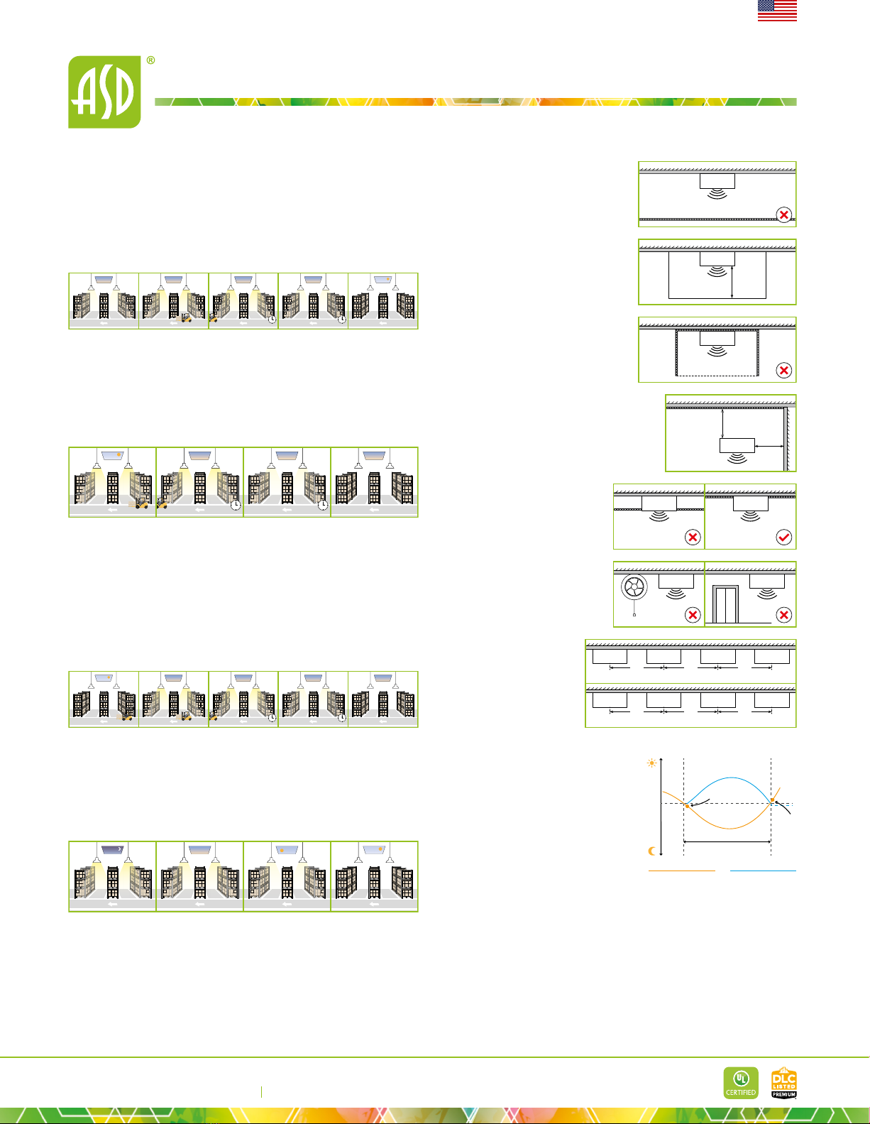
WITH DAYLIGHT DISABLED:
1. Sensor turns ON light when motion is detected.
2.
3.
motion.
4.
hold time stand-by period
2314
WITH DAYLIGHT THRESHOLD:
1.
2.
3.
4.
holdtime.
5.
no motion detected.
hold time stand-by period
45
123
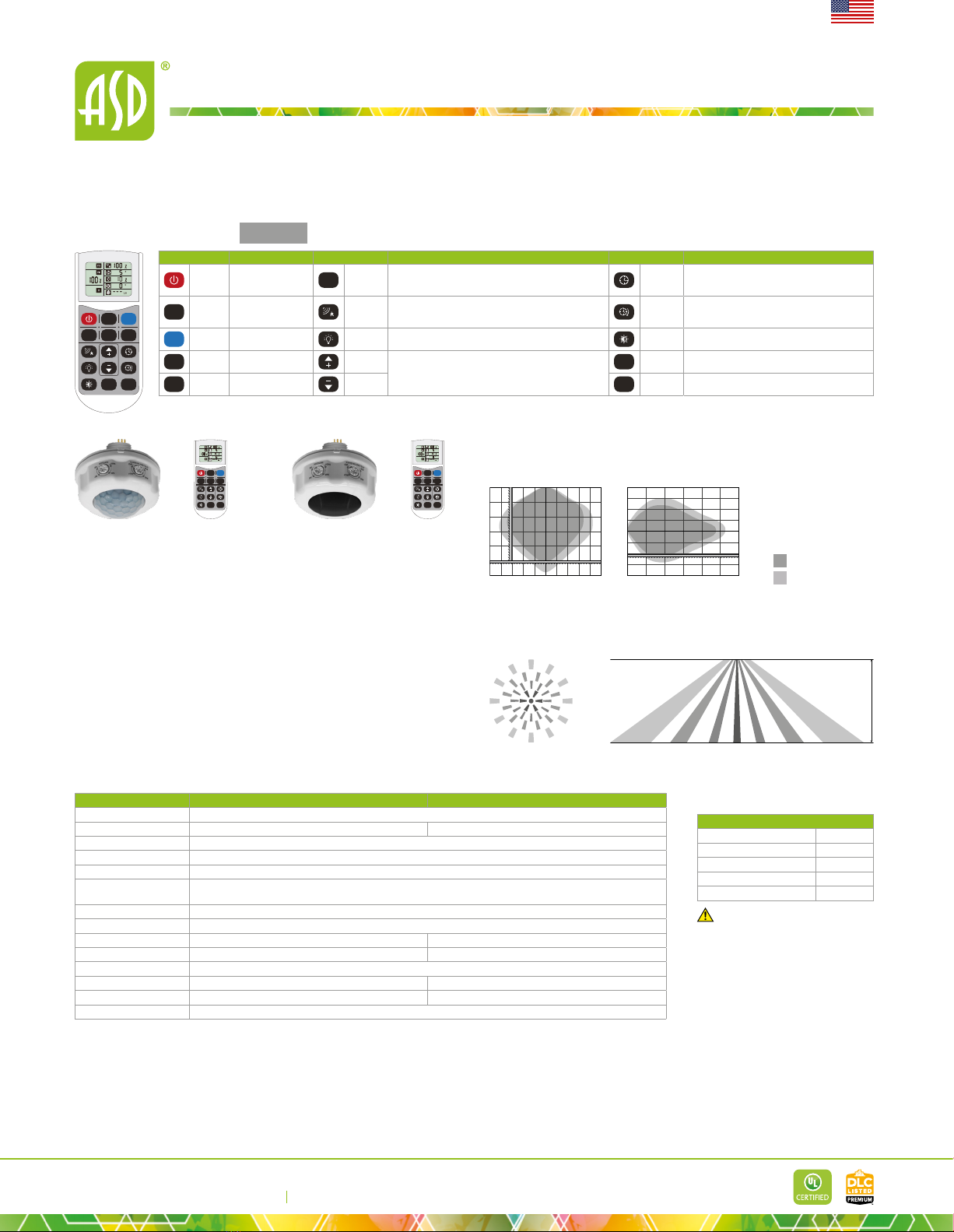
The distance between the antenna and
the glass (dielectric material) should be
within the glass lampshade. Otherwise,
the microwave motion sensor will not
penetrate the glass easily.
0.4ſt
glass lampshade
sensor
Avoid placing the sensor inside a metal
chamber, this may cause a mis-trigger.
metal chamber
sensor
To avoid blocking the microwave
emission, the microwave sensor can
not be covered with metal materials,
be sprayed with a coating of metal
components, or have attached metal
material or stickers etc.
metal
sensor
The sensor should not be placed in a small
detection range or abnormal operation, the
sensor should be kept away from large areas of
metal reflector
sensor
3.3ſt
3.3ſt
Any vibration or movement may
trigger the sensor. Ensure the
sensor is far from any constant
movement.
signal transmission, the microwave
antenna should be higher than the
surrounding metal surface. metal metal
metal metal
sensorsensor
vibration elevator
sensorsensor
When multiple sensors are
installed side-by-side in the
same direction, the distance
between each sensor
(the warehouse sensors at
interference.
sensor sensor sensor sensor
3.3ſt 3.3ſt 3.3ſt
sensor sensor sensor sensor
9.8ſt 9.8ſt 9.8ſt
multi sensors are installed in the same direction
multi warehouse sensors are installed in the same direction
WITH DUSK/DAWN FUNCTION:
hold time stand-by period
34512
1.
standby dimming level even if there is no motion or presence.
2. When sensor detects motion or presence it will bring the light level up to 100 %.
3.
4.
always keep it.
5.
DAYLIGHT HARVESTING: DAYLIGHT HARVESTING
SETTING:
1. When ambient brightness is lower than preset lux level, sensor will turn on
light automatically and keep dimming according to the change of the ambient
2. Light OFF when ambient brightness becomes higher than the preset lux level.
1. Adjust "daylight" value higher than
50lux.
2. Preset "standby period" 0S
3. Press MW/PIR button 3 times till MW/
PIR icons both blinking on LCD screen,
daylight harvesting function enabled.
(With BLE version, press DH button,
daylight harvesting function enabled).
12
Daylight harvesting phase
Preset
lux value
Light OFF
Light ON
Natural light brightness Artificial light brightness
Only for HD09VR-MH and HD09VR-PH models.

E-mail: [email protected]
ASD LIGHTING CORP
Web site: www.asd-lighting.com
For most up-to-date spec sheets please refer to asd-lighting.com
English
Q-BASE LED LOW-PROFILE CANOPY
BUILT-IN BATTERY BACK-UP INFORMATION
Specications Model: BLD-CM20H-1500400
Input voltage z
Max emergency output power 15W
Warranty 5 years
Indicator light Illuminated test switch, indicator light
Battery Li-ion - 11.1 V / 4000 mAh
Lumens 2,194 lm
Emergency operation time
Battery charging current 250 mA
Emergency current 170 mA
Charging time
Full charge/discharge cycles 500 cycles
STANDARD OPERATION DISPLAY STATUS:
Charging
Emergency mode
Indicator light modes:
• Red light ON - the battery back-up is charging in standby mode;
• Red light OFF - AC power is out, the battery back-up is working in emergency mode.
Test button operation: Press the test button to switch the system to back-up mode. The
back to the normal mode.
INSTALLATION GUIDE
IMPORTANT SAFETY INFORMATION:
Please read all the instructions below before installation.
Make sure that the supply voltage corresponds to the rated product voltage.
National Electrical Code and corresponding local codes.
If the product is damaged, do not use it.
WARNING
RISK OF PERSONAL INJURY – READ and follow all WARNINGS and
installation instructions. Keep or give to the owner for future reference.
Risk of cuts: Wear gloves to prevent cuts or abrasions when removing from
carton, handling, installing, and maintaining this product.
Risk of electric shock: This product must be installed in accordance with the
applicable installation code by a person familiar with the construction and
operation of the product and the hazards involved.
Risk of Fire:
ensure correct branch circuit conductor.
ASD® assumes no responsibility for claims arising out of improper or careless
Installation or handling of this product.
CAN07A-EM with battery back-up
CAN07A-EM with motion sensor and battery back-up
Led 2
L
N
G
Switch
L
N
G
BATTERY
BACKUP
+
-
Test switch Indicator light
Led - (Black)
Led + (Red)
Power
connector
120-277 V *
FIXTURE
L
N
G
DRIVER
G
-
+
Dim + (Violet)
Dim - (Pink)
Led 1
Led 1
Led 2
L
N
G
Switch
L
N
G
BATTERY
BACKUP
+
-
Test switch Indicator light
Led - (Black)
Led + (Red)
Power
connector
120-277 V *
FIXTURE
L
N
G
DRIVER
G
-
+
Dim + (Violet)
Dim - (Pink)
Dim + Dim - 12V +
MOTION SENSOR
phase circuit with phase-to-phase voltage of 208V (L1-120V & L2-120V).
WARNING: Phase-to-phase voltage should be less than 277V (160V per each phase) and
ELECTRICAL SCHEMATIC DIAGRAM:
CAN07A
Power
connector
120-277 V *
L
N
GGround connect green
L (live/hot) connect black
N (neutral) connect white
L
N
G
DRIVER
Dim + (Violet)
Dim - (Pink)
FIXTURE
CAN07A with motion sensor
120-277 V *
L
N
G
Ground connect green
L (live/hot) connect black
N (neutral) connect white
L
N
G
DRIVER
Power
connector
FIXTURE
Dim + (Violet)
Dim - (Pink)
Dim + Dim - 12V +
MOTION SENSOR

E-mail: [email protected]
ASD LIGHTING CORP
Web site: www.asd-lighting.com
For most up-to-date spec sheets please refer to asd-lighting.com
English
Q-BASE LED LOW-PROFILE CANOPY
POLE MOUNTING INSTALLATION:
1. Remove the rubber cap, pass the AC wires from conduit through the hole into
2.
White to White, Green to Green.
3.
1 2
3
SURFACE MOUNT WITH A MOUNTING PLATE:
1. Remove the securing screw out of the mounting plate, detach the mounting
anchors and self-tapping screws.
2.
connection to the Junction box in the ceiling.
3.
3
21
2
1
MOTION SENSOR
INSTALLATION
1. Unscrew the microwave sensor base
cap.
2. Insert and twist the sensor until it is
tight on the base surface.
sold separately:
HD09VR-MH HD09VR-PH
This manual suits for next models
7
Table of contents
Other ASD Lighting Equipment manuals