ASD LED UFO HIGH BAY User manual

LED UFO HIGH BAY
E-mail: [email protected]
ASD LIGHTING CORP
Web site: www.asd-lighting.com
For most up-to-date spec sheets please refer to asd-lighting.com
English
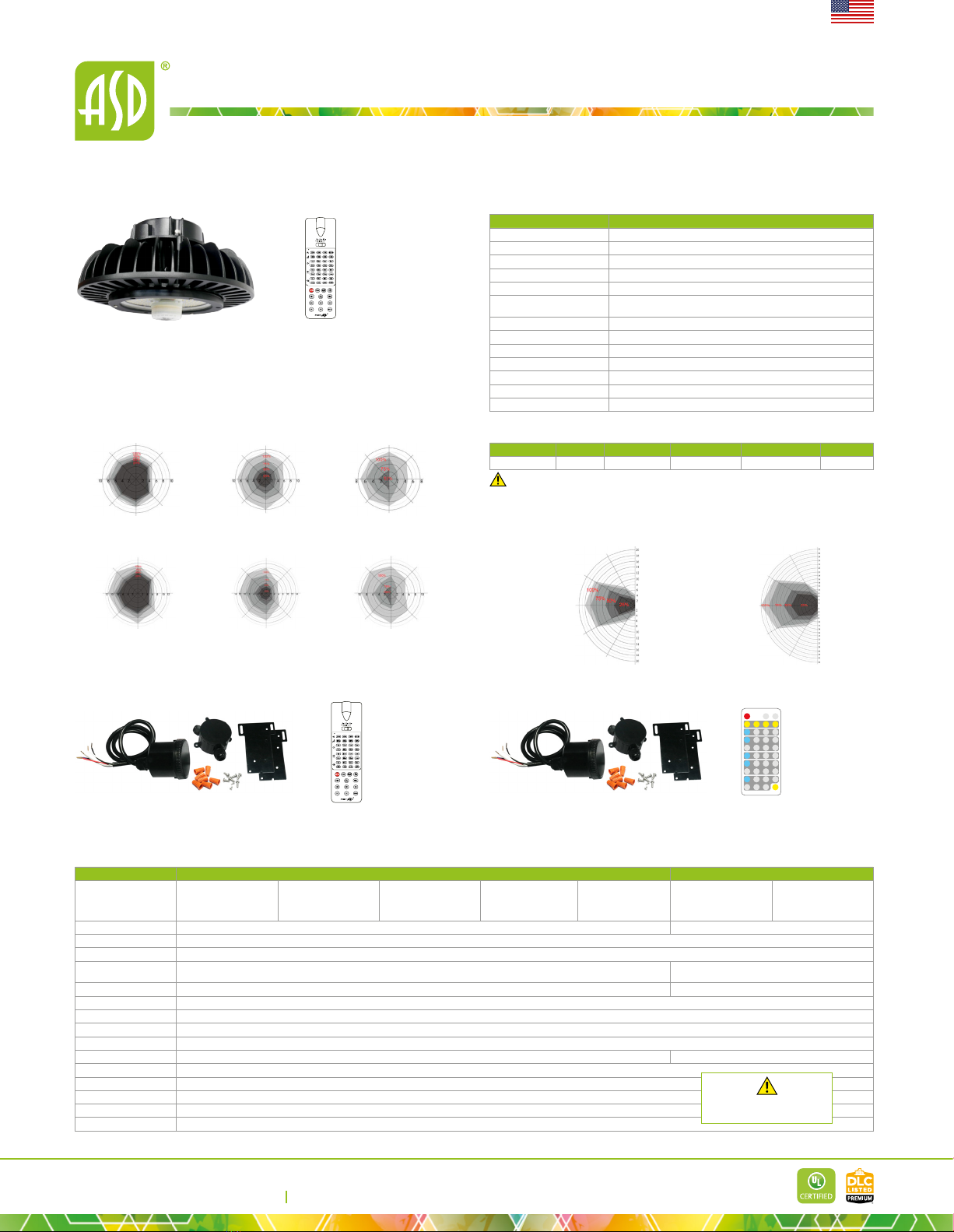
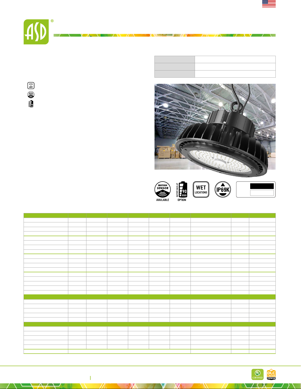
▶DESIGN & OPTIONS - LED UFO HIGH BAY is extremely ecient with
a 150lm/W output and are equipped with 1-10V dimmable drivers at 120-277V.
Diecast aluminum housing also provides excellent heat dissipation. You can
choose either 3,500K, 4,000K or 5,000K color temperature. Additional options
include: motion sensor kit for higher energy savings, and dierent types of
reectors and lenses (sold separately). Comes with a WHITE or BLACK nish.
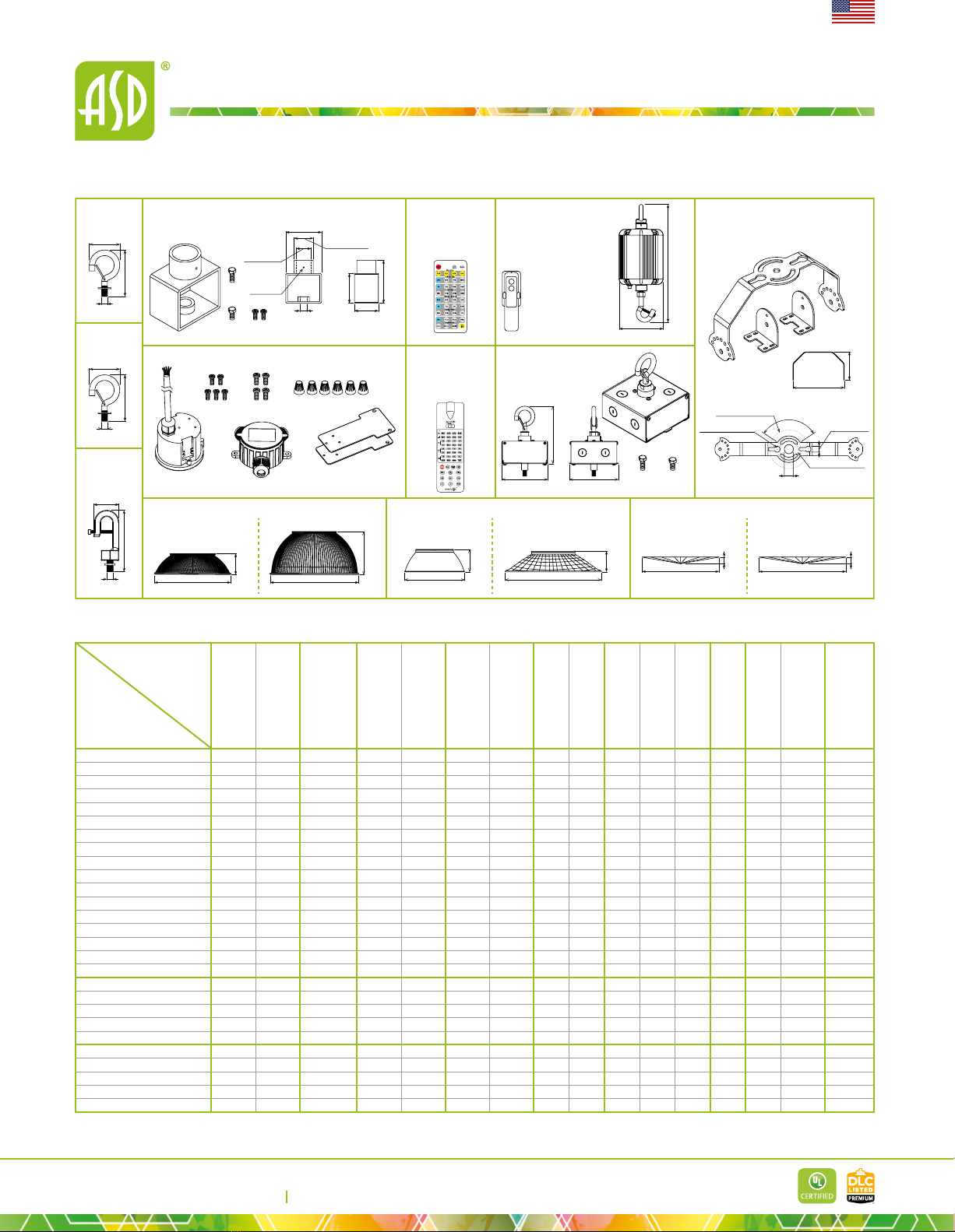
▶INSTALLATION - This xture has three dierent mounting options:
suspended, surface, and pendant. It can easily be suspended from the ceiling with
the included hanging ring. Surface and pendant mount brackets are also available
(sold separately). Refer to install instructions for detailed steps.
▶APPLICATION - These lights are the perfect commercial or industrial
solution for warehouses, supermarkets, retail stores, gyms, garages, general task
areas, and many other applications. This xture is IP65 and IP69K rated and is
resistant to high pressure, temperature, water, and dust. These LED UFO HIGH BAY
LIGHTS can operate in temperatures between -40 to 149°F (-40 to 65°C), allowing
them to be utilized in a wide variety of applications and climates.
▶ENERGY SAVING & EFFICIENCY - With a calculated lifespan up to
154,000 hours, these xtures are made to last decades under normal operation!
This xture can cut your electric bill by up to 80% instantly and will save you a
signicant amount of money in its lifetime.
▶CERTIFICATION & WARRANTY - Buy with condence: ASD provides
a 5-year limited warranty along with UL certication to guarantee top quality
products and safety!
DLC Premium classication allow participation in rebates; please check the rebate
programs available in your state.
White
Black
Finish:
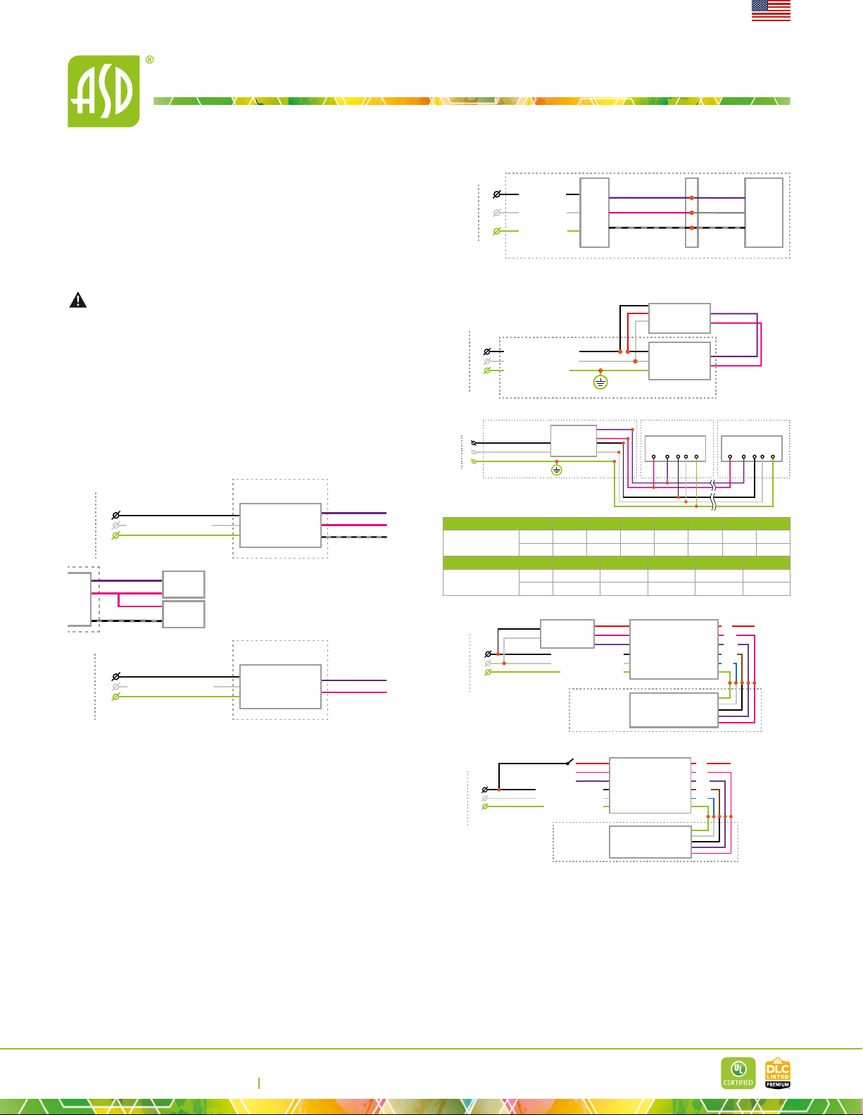
Models with High Voltage driver (277-480V) are available.
Models with a built-in microwave motion sensor automatically turn o
in the absence of motion and can be programmed via wireless remote.
The battery back-up kit provides 90 minutes of power in case of
emergency.
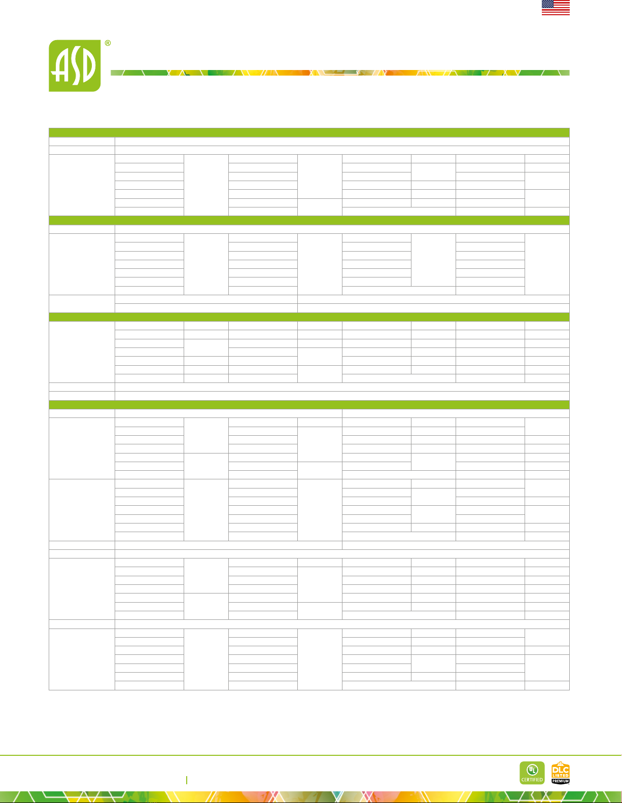
Model Watts Voltage Dimmable Lumens CCT Finish Dimensions (LxWxH) Cord Option
ASD-UHB2-100D35-PRM 100W 120-277 V 1-10 V 14,600 lm 3,500 K Black 10-1/4" x 10-1/4" x 6-1/4" 4 -
ASD-UHB2-100D40W-PRM 100W 120-277 V 1-10 V 14,700 lm 4,000 K White 10-1/4" x 10-1/4" x 6-1/4" 4 -
ASD-UHB2-100D50-PRM 100W 120-277 V 1-10 V 14,800 lm 5,000 K Black 10-1/4" x 10-1/4" x 6-1/4" 4 -
ASD-UHB2-100D50W-PRM 100W 120-277 V 1-10 V 14,800 lm 5,000 K White 10-1/4" x 10-1/4" x 6-1/4" 4 -
ASD-UHB2-150D35-PRM 150W 120-277 V 1-10 V 21,900 lm 3,500 K Black 10-1/4" x 10-1/4" x 6-7/8" 4 -
ASD-UHB2-150D40W-PRM 150W 120-277 V 1-10 V 22,050 lm 4,000 K White 10-1/4" x 10-1/4" x 6-7/8" 4 -
ASD-UHB2-150D50-PRM 150W 120-277 V 1-10 V 22,200 lm 5,000 K Black 10-1/4" x 10-1/4" x 6-7/8" 4 -
ASD-UHB2-150D50W-PRM 150W 120-277 V 1-10 V 22,200 lm 5,000 K White 10-1/4" x 10-1/4" x 6-7/8" 4 -
ASD-UHB2-200D35-PRM 200W 120-277 V 1-10 V 29,200 lm 3,500 K Black 10-1/4" x 10-1/4" x 6-7/8" 4 -
ASD-UHB2-200D40W-PRM 200W 120-277 V 1-10 V 29,400 lm 4,000 K White 10-1/4" x 10-1/4" x 6-7/8" 4 -
ASD-UHB2-200D50-PRM 200W 120-277 V 1-10 V 29,600 lm 5,000 K Black 10-1/4" x 10-1/4" x 6-7/8" 4 -
ASD-UHB2-200D50W-PRM 200W 120-277 V 1-10 V 29,600 lm 5,000 K White 10-1/4" x 10-1/4" x 6-7/8" 4 -
ASD-UHB2-240D50-PRM 240W 120-277 V 1-10 V 35,520 lm 5,000 K Black 12-9/16" x 12-9/16" x 6-3/4" 4 -
ASD-UHB2-240D50W-PRM 240W 120-277 V 1-10 V 35,520 lm 5,000 K White 12-9/16" x 12-9/16" x 6-3/4" 4 -
ASD-UHB2-300D50-PRM 300W 120-277 V 1-10 V 45,000 lm 5,000 K Black 12-9/16" x 12-9/16" x 7-3/4" 4 -
ASD-UHB2-400D50-PRM 400W 120-277 V 0-10 V 60,000 lm 5,000 K Black 14-1/8" x 14-1/8" x 9-1/4" 4 -
ASD-UHB2-500D50-PRM 500W 120-277 V 0-10 V 75,000 lm 5,000 K Black 14-1/8" x 14-1/8" x 9-1/4" 4 -
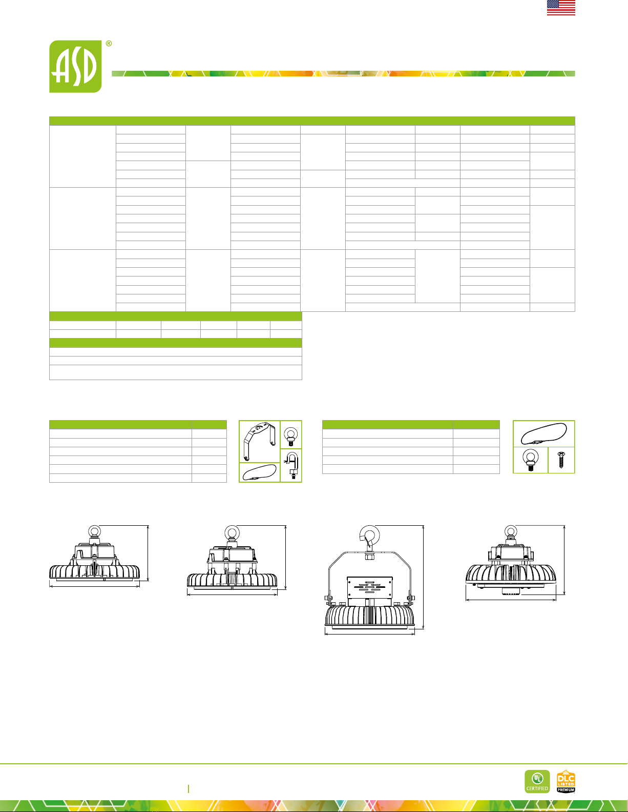
UHB2 HIGH VOLTAGE
ASD-UHB2HV-150D50-PRM 150W 277-480 V 0-10 V 22,500 lm 5,000 K Black 10-1/4" x 10-1/4" x 7-5/16" 4 -
ASD-UHB2HV-200D50-PRM 200W 277-480 V 0-10 V 30,000 lm 5,000 K Black 10-1/4" x 10-1/4" x 7-1/4" 4 -
ASD-UHB2HV-300D50-PRM 300W 277-480 V 0-10 V 45,028 lm 5,000 K Black 12-5/8" x 12-5/8" x 8-1/4" 4 -
ASD-UHB2HV-400D50-PRM 400W 277-480 V 0-10 V 56,053 lm 5,000 K Black 14-3/16" x 14-3/16" x 12-1/8" 4 -
ASD-UHB2HV-500D50-PRM 500W 277-480 V 0-10 V 69,185 lm 5,000 K Black 14-3/16" x 14-3/16" x 12-1/8" 4 -
UHB22-MS WITH MOTION SENSOR
ASD-UHB22-100D50-MS 100W 120-277V 1-10 V 14,800 lm 5,000 K Black 10-1/4" x 10-1/4" x 7-1/2" 4 Motion sensor
ASD-UHB22-150D50-MS 150W 120-277V 1-10 V 22,200 lm 5,000 K Black 10-1/4" x 10-1/4" x 7-1/2" 4 Motion sensor
ASD-UHB22-200D50-MS 200W 120-277V 1-10 V 29,600 lm 5,000 K Black 11-7/16" x 11-7/16" x 7-7/8" 4 Motion sensor
ASD-UHB22-240D50-MS 240W 120-277V 1-10 V 35,520 lm 5,000 K Black 11-7/16" x 11-7/16" x 7-7/8" 4 Motion sensor
ASD-UHB22-300D50-MS 300W 120-277V 0-10 V 45,000 lm 5,000 K Black 12-5/8" x 12-5/8" x 8-3/16" 4 Motion sensor
UHB-RC-MSK1 Remote controller for motion sensor 6-7/8" x 2-1/4" x 1-1/16" - -
Catalog number
Notes
Type

LED UFO HIGH BAY
E-mail: [email protected]
ASD LIGHTING CORP
Web site: www.asd-lighting.com
For most up-to-date spec sheets please refer to asd-lighting.com
English
PRODUCT SPECIFICATIONS:
Electrical system
Input voltage Regular voltage: 120-277 V High voltage: 277-480 V
Max input current
ASD-UHB2-100D35-PRM
1.3 A
ASD-UHB2-150D50W-PRM 2 A ASD-UHB2-300D50-PRM 3.8 A ASD-UHB2HV-400D50-PRM 1.8 A
ASD-UHB2-100D40W-PRM ASD-UHB2-200D35-PRM
2.6 A
ASD-UHB2-400D50-PRM 4.5 A ASD-UHB2HV-500D50-PRM
ASD-UHB2-100D50-PRM ASD-UHB2-200D40W-PRM ASD-UHB2-500D50-PRM 5.8 A ASD-UHB22-100D50-MS 1.2 A
ASD-UHB2-100D50W-PRM ASD-UHB2-200D50-PRM ASD-UHB2HV-150D50-PRM 0.8 A ASD-UHB22-150D50-MS 1.8 A
ASD-UHB2-150D35-PRM
2 A
ASD-UHB2-200D50W-PRM ASD-UHB2HV-200D50-PRM 1.2 A ASD-UHB22-200D50-MS 2.4 A
ASD-UHB2-150D40W-PRM ASD-UHB2-240D50-PRM 2.95 A ASD-UHB2HV-300D50-PRM ASD-UHB22-240D50-MS 2.8 A
ASD-UHB2-150D50-PRM ASD-UHB2-240D50W-PRM ASD-UHB22-300D50-MS 3.8 A
Inrush current
(Action time)
ASD-UHB2-100D35-PRM
80 A (0.5 S)
ASD-UHB2-150D50W-PRM
80 A (0.5 S)
ASD-UHB2-300D50-PRM 120 A (0.5 S) ASD-UHB2HV-400D50-PRM 50/90 A (0.5 S)
ASD-UHB2-100D40W-PRM ASD-UHB2-200D35-PRM ASD-UHB2-400D50-PRM 60 A (<1 S) ASD-UHB2HV-500D50-PRM
ASD-UHB2-100D50-PRM ASD-UHB2-200D40W-PRM ASD-UHB2-500D50-PRM ASD-UHB22-100D50-MS 60 A (0.5 S)
ASD-UHB2-100D50W-PRM ASD-UHB2-200D50-PRM ASD-UHB2HV-150D50-PRM 190 A (0.5 S) ASD-UHB22-150D50-MS 100 A (0.5 S)
ASD-UHB2-150D35-PRM ASD-UHB2-200D50W-PRM ASD-UHB2HV-200D50-PRM ASD-UHB22-200D50-MS
ASD-UHB2-150D40W-PRM ASD-UHB2-240D50-PRM ASD-UHB2HV-300D50-PRM 90 A (0.5 S) ASD-UHB22-240D50-MS 60 A (0.5 S)
ASD-UHB2-150D50-PRM ASD-UHB2-240D50W-PRM ASD-UHB22-300D50-MS 120 A (0.5 S)
AC input range Regular voltage: min 90 V max 305 V High voltage: min 249 V max 528 V
O state power 0W
Power consumption
ASD-UHB2-100D35-PRM
100W
ASD-UHB2-150D50W-PRM 150W ASD-UHB2-300D50-PRM 300W ASD-UHB2HV-400D50-PRM 400W
ASD-UHB2-100D40W-PRM ASD-UHB2-200D35-PRM
200W
ASD-UHB2-400D50-PRM 400W ASD-UHB2HV-500D50-PRM 500W
ASD-UHB2-100D50-PRM ASD-UHB2-200D40W-PRM ASD-UHB2-500D50-PRM 500W ASD-UHB22-100D50-MS 100W
ASD-UHB2-100D50W-PRM ASD-UHB2-200D50-PRM ASD-UHB2HV-150D50-PRM 150W ASD-UHB22-150D50-MS 150W
ASD-UHB2-150D35-PRM
150W
ASD-UHB2-200D50W-PRM ASD-UHB2HV-200D50-PRM 200W ASD-UHB22-200D50-MS 200W
ASD-UHB2-150D40W-PRM ASD-UHB2-240D50-PRM 240W ASD-UHB2HV-300D50-PRM 300W ASD-UHB22-240D50-MS 240W
ASD-UHB2-150D50-PRM ASD-UHB2-240D50W-PRM ASD-UHB22-300D50-MS 300W
Power factor > 0.9
Output voltage
ASD-UHB2-100D35-PRM
180-260 V
ASD-UHB2-150D50W-PRM
180-260 V
ASD-UHB2-300D50-PRM 28-56 V ASD-UHB2HV-400D50-PRM 22-56 V
ASD-UHB2-100D40W-PRM ASD-UHB2-200D35-PRM ASD-UHB2-400D50-PRM 171-228 V ASD-UHB2HV-500D50-PRM
ASD-UHB2-100D50-PRM ASD-UHB2-200D40W-PRM ASD-UHB2-500D50-PRM 114-228 V ASD-UHB22-100D50-MS 90-130 V
ASD-UHB2-100D50W-PRM ASD-UHB2-200D50-PRM ASD-UHB2HV-150D50-PRM 22-56 V ASD-UHB22-150D50-MS
180-260 VASD-UHB2-150D35-PRM ASD-UHB2-200D50W-PRM ASD-UHB2HV-200D50-PRM ASD-UHB22-200D50-MS
ASD-UHB2-150D40W-PRM ASD-UHB2-240D50-PRM ASD-UHB2HV-300D50-PRM 114-228 V ASD-UHB22-240D50-MS
ASD-UHB2-150D50-PRM ASD-UHB2-240D50W-PRM ASD-UHB22-300D50-MS 28-56 V
Optical system
Luminous ux
ASD-UHB2-100D35-PRM 14,600 lm ASD-UHB2-150D50W-PRM 22,200 lm ASD-UHB2-300D50-PRM 45,000 lm ASD-UHB2HV-400D50-PRM 56,053 lm
ASD-UHB2-100D40W-PRM 14,700 lm ASD-UHB2-200D35-PRM 29,200 lm ASD-UHB2-400D50-PRM 60,000 lm ASD-UHB2HV-500D50-PRM 69,185 lm
ASD-UHB2-100D50-PRM 14,800 lm ASD-UHB2-200D40W-PRM 29,400 lm ASD-UHB2-500D50-PRM 75,000 lm ASD-UHB22-100D50-MS 14,800 lm
ASD-UHB2-100D50W-PRM ASD-UHB2-200D50-PRM 29,600 lm ASD-UHB2HV-150D50-PRM 22,500 lm ASD-UHB22-150D50-MS 22,200 lm
ASD-UHB2-150D35-PRM 21,900 lm ASD-UHB2-200D50W-PRM ASD-UHB2HV-200D50-PRM 30,000 lm ASD-UHB22-200D50-MS 29,600 lm
ASD-UHB2-150D40W-PRM 22,050 lm ASD-UHB2-240D50-PRM 35,520 lm ASD-UHB2HV-300D50-PRM 45,028 lm ASD-UHB22-240D50-MS 35,520 lm
ASD-UHB2-150D50-PRM 22,200 lm ASD-UHB2-240D50W-PRM ASD-UHB22-300D50-MS 45,000 lm
Color temperature 3,500 K; 4,000 K; 5,000 K
CRI > 70
Environmental system
Work environment Suitable for Wet Locations, IP65/69K
Operating temperature
ASD-UHB2-100D35-PRM
-40℉ to 149℉ /
-40℃ to 65℃ *
ASD-UHB2-150D50W-PRM
-40℉ to 149℉ /
-40℃ to 65℃ *
ASD-UHB2-300D50-PRM
-40℉ to 149℉ /
-40℃ to 65℃ *
ASD-UHB2HV-400D50-PRM
-22°F to 140°F /
-30°C to 60°C
**
ASD-UHB2-100D40W-PRM ASD-UHB2-200D35-PRM ASD-UHB2-400D50-PRM ASD-UHB2HV-500D50-PRM
ASD-UHB2-100D50-PRM ASD-UHB2-200D40W-PRM ASD-UHB2-500D50-PRM ASD-UHB22-100D50-MS
ASD-UHB2-100D50W-PRM ASD-UHB2-200D50-PRM ASD-UHB2HV-150D50-PRM ASD-UHB22-150D50-MS
ASD-UHB2-150D35-PRM ASD-UHB2-200D50W-PRM ASD-UHB2HV-200D50-PRM ASD-UHB22-200D50-MS
ASD-UHB2-150D40W-PRM ASD-UHB2-240D50-PRM ASD-UHB2HV-300D50-PRM ASD-UHB22-240D50-MS
ASD-UHB2-150D50-PRM ASD-UHB2-240D50W-PRM ASD-UHB22-300D50-MS
L-70 Life for UHB2: R > 54,000 hrs; C > 152,000 hrs for ASD-UHB2-400D50-PRM, ASD-UHB2-500D50-PRM: R > 60,000 hrs; C > 154,000 hrs
for UHB22: R > 54,000 hrs; C > 145,000 hrs for ASD-UHB2HV-400D50-PRM, ASD-UHB2HV-500D50-PRM: R > 60,000 hrs; C > 143,000 hrs
Construction & Materials
Housing Die cast aluminum
Finish Black, White
Weight
ASD-UHB2-100D35-PRM
6.2 lb (2.8 kg)
ASD-UHB2-150D50W-PRM
6.2 lb (2.8 kg)
ASD-UHB2-300D50-PRM 10.1 lb (4.6 kg) ASD-UHB2HV-400D50-PRM 21.6 lb (9.8 kg)
ASD-UHB2-100D40W-PRM ASD-UHB2-200D35-PRM ASD-UHB2-400D50-PRM 17 lb (7.7 kg) ASD-UHB2HV-500D50-PRM 22 lb (10 kg)
ASD-UHB2-100D50-PRM ASD-UHB2-200D40W-PRM ASD-UHB2-500D50-PRM ASD-UHB22-100D50-MS 7.1 lb (3.2 kg)
ASD-UHB2-100D50W-PRM ASD-UHB2-200D50-PRM ASD-UHB2HV-150D50-PRM 6.6 lb (3 kg) ASD-UHB22-150D50-MS
ASD-UHB2-150D35-PRM ASD-UHB2-200D50W-PRM ASD-UHB2HV-200D50-PRM 8.8 lb (4 kg) ASD-UHB22-200D50-MS 9.3 lb (4.2 kg)
ASD-UHB2-150D40W-PRM ASD-UHB2-240D50-PRM 8.2 lb (3.7 kg) ASD-UHB2HV-300D50-PRM 13.7 lb (6.2 kg) ASD-UHB22-240D50-MS
ASD-UHB2-150D50-PRM ASD-UHB2-240D50W-PRM ASD-UHB22-300D50-MS 10.4 lb (4.7 kg)

LED UFO HIGH BAY
E-mail: [email protected]
ASD LIGHTING CORP
Web site: www.asd-lighting.com
For most up-to-date spec sheets please refer to asd-lighting.com
English
Electrical system
Driver output current
ASD-UHB2-100D35-PRM
400 mA
ASD-UHB2-150D50W-PRM 600 mA ASD-UHB2-300D50-PRM 5.6 A ASD-UHB2HV-400D50-PRM 3.75 A * 2
ASD-UHB2-100D40W-PRM ASD-UHB2-200D35-PRM
800 mA
ASD-UHB2-400D50-PRM 1.75 A ASD-UHB2HV-500D50-PRM 4.7 A * 2
ASD-UHB2-100D50-PRM ASD-UHB2-200D40W-PRM ASD-UHB2-500D50-PRM 2.2 A ASD-UHB22-100D50-MS 750 mA
ASD-UHB2-100D50W-PRM ASD-UHB2-200D50-PRM ASD-UHB2HV-150D50-PRM 2.8 A ASD-UHB22-150D50-MS 600 mA
ASD-UHB2-150D35-PRM
600 mA
ASD-UHB2-200D50W-PRM ASD-UHB2HV-200D50-PRM 3.75 A ASD-UHB22-200D50-MS
ASD-UHB2-150D40W-PRM ASD-UHB2-240D50-PRM 950 mA ASD-UHB2HV-300D50-PRM 1.25 A ASD-UHB22-240D50-MS 1 A
ASD-UHB2-150D50-PRM ASD-UHB2-240D50W-PRM ASD-UHB22-300D50-MS 5.6 A
Surge protection DM/CM
ASD-UHB2-100D35-PRM
6 kV / 6 kV
ASD-UHB2-150D50W-PRM
6 kV / 6 kV
ASD-UHB2-300D50-PRM 6 kV / 6 kV ASD-UHB2HV-400D50-PRM 6 kV / 10 kV
ASD-UHB2-100D40W-PRM ASD-UHB2-200D35-PRM ASD-UHB2-400D50-PRM 6 kV / 10 kV ASD-UHB2HV-500D50-PRM
ASD-UHB2-100D50-PRM ASD-UHB2-200D40W-PRM ASD-UHB2-500D50-PRM ASD-UHB22-100D50-MS
6 kV / 6 kV
ASD-UHB2-100D50W-PRM ASD-UHB2-200D50-PRM ASD-UHB2HV-150D50-PRM 4 kV / 4 kV ASD-UHB22-150D50-MS
ASD-UHB2-150D35-PRM ASD-UHB2-200D50W-PRM ASD-UHB2HV-200D50-PRM ASD-UHB22-200D50-MS
ASD-UHB2-150D40W-PRM ASD-UHB2-240D50-PRM ASD-UHB2HV-300D50-PRM 6 kV / 10 kV ASD-UHB22-240D50-MS
ASD-UHB2-150D50-PRM ASD-UHB2-240D50W-PRM ASD-UHB22-300D50-MS
LED driver class
ASD-UHB2-100D35-PRM
Non-isolated
ASD-UHB2-150D50W-PRM
Non-isolated
ASD-UHB2-300D50-PRM
Class P
ASD-UHB2HV-400D50-PRM Class P
ASD-UHB2-100D40W-PRM ASD-UHB2-200D35-PRM ASD-UHB2-400D50-PRM ASD-UHB2HV-500D50-PRM
ASD-UHB2-100D50-PRM ASD-UHB2-200D40W-PRM ASD-UHB2-500D50-PRM ASD-UHB22-100D50-MS
Non-isolated
ASD-UHB2-100D50W-PRM ASD-UHB2-200D50-PRM ASD-UHB2HV-150D50-PRM ASD-UHB22-150D50-MS
ASD-UHB2-150D35-PRM ASD-UHB2-200D50W-PRM ASD-UHB2HV-200D50-PRM ASD-UHB22-200D50-MS
ASD-UHB2-150D40W-PRM ASD-UHB2-240D50-PRM ASD-UHB2HV-300D50-PRM ASD-UHB22-240D50-MS
ASD-UHB2-150D50-PRM ASD-UHB2-240D50W-PRM ASD-UHB22-300D50-MS Class P
Dimming compatible controls ***
Brand Maxxima Keygma Lutron Leviton Eaton
Models MEW-DM600LV KGM-1A010V DVSTV-WH IP710-DLZ DF10P-C1
Regular and voluntary certications
5-year limited warranty
UL certied E473804
DesignLights Consortium (DLC) listed (Classication: Premium series) Main: Indoor Luminaires;
General Application: High-Bay; Primary Use: High-Bay Luminaires for Commercial and Industrial Buildings.
* Under extreme conditions xture may enter protection mode. If ambient temperature exceeds 65°C (149°F) for an
extended period lumen output will decrease to 60% capacity. At higher sustained temperatures protection mode will
terminate power to the xture.
** Under extreme conditions xture may enter protection mode. If ambient temperature exceeds 60°C (140°F) for an
extended period lumen output will decrease to 60% capacity, sensor detection radius may be shortened. At higher sustained
temperatures protection mode will terminate power to the xture.
*** The list of dimmers is relevant for models without a motion sensor.
UHB2HV 400-500W
14-3/16" (360 mm)
16-1/4" (413 mm)
UHB22
10-1/4" (260 mm)
7-1/2" (206 mm)
UHB2
10-1/4" (260 mm)
6-1/4" (159 mm)
UHB2HV
10-1/4" (260 mm)
7-5/16" (185 mm)
*Screws are already installed in the attachment points of the UFO housing.
Description Q-ty
LED UFO High Bay Fixture 1
Safety cable (A) 1
Mounting ring (B) 1
Screw for reector installation (C)* 1
Box 1
PACKAGE CONTENTS FOR UHB22:
C
A
B
Description Q-ty
LED UFO High Bay Fixture 1
Bracket (A) (only for 300W, 400W, 500W HV models) 1
Safety cable (B) 1
Mounting ring (C) 1
Screw-bolt hook (D) (only for 400W, 500W model) 1
Box 1
PACKAGE CONTENTS FOR UHB2:
CA
B
D

LED UFO HIGH BAY
E-mail: [email protected]
ASD LIGHTING CORP
Web site: www.asd-lighting.com
For most up-to-date spec sheets please refer to asd-lighting.com
English
ACCESSORIES (sold separately):
Plastic J-box
Mounting plate:
A - for microwave motion sensor
B - for plastic J-box
Motion sensor kit
Aluminum reflector Polycarbonate bottom conical lens
Microwave
motion sensor
Wiring cap
Polycarbonate reflector
Battery back-up
kit 40W
Remote test
switch for battery
back-up kit
Surface mount bracketPendant mount bracketSpring hook
Spring hook
Screw-bolt
hook
Pendant mount bracket
with J-box and spring hook
ASD-SMB100/300-UHB2
ASD-SMB100/300-UHB2W
M10
M12
Remote controller
for motion sensor
UHB-MSK1
UHB-RC-MSK1
ASD-H-M12
ASD-H-M10
ASD-HS-M10
BLD-UM40R
ASD-PMBJB-UHB
ASD-PMB-UHB
Remote controller
for motion sensor
UHBHV-MSK2
ASD-CELP02H-MS
M3 M4
UHB-MSK1 UHBHV-MSK2
RN1
ON
OFF
M3
4-3/4" (120 mm) 5-1/16" (128 mm)
7-3/16" (183 mm)
4-9/16" (115.8 mm)
12-3/16" (310 mm)
5-5/16" (135 mm)
9-11/16" (246 mm)
2-5/16" (59 mm)
3-1/2" (89 mm)
1" (25 mm)
2-1/8" (53 mm)
3-5/16" (84 mm)
7/8" (22.6 mm)
1-5/8" (40.8 mm)
3-7/8" (98 mm)
1-1/4" (32.5 mm)
d 4-1/2" (115.35 mm) 119.8°
5/8" (18 mm)
d 2-3/4" (69.66 mm)
d 2-1/4" (57.56 mm)
1-1/16" (27.5 mm)
21" 120˚
ASD-DUHB-21-120ALG
16" 90˚
ASD-DUHB-16-90AL
for 19"
ASD-BLUHB-19PCASD-BLUHB-16PC
for 16"
19" 90˚
ASD-DUHB-19-90PC
ASD-DUHB-16-90PC
16" 90˚
1-7/8" (47 mm)
18-11/16" (475 mm)15-15/16 " (404 mm)
1-1/2" (38 mm)
21" (535 mm)
4-1/8" (105 mm)
15-3/4" (400 mm)
5-1/8" (132 mm)
18-7/8" (480 mm)
5-1/2" (140 mm)
16-1/4" (415 mm)
3-7/8" (98 mm)
M10
M12
1-5/8" (40 mm)
2-7/8" (72 mm)
1-15/16" (50 mm)
1-1/4" (32 mm)
1/2" (13 mm)
2-3/8" (60 mm)
Inner thread
3/4 -14 NPT
M3 internal
thread
ACCESSORY COMPATIBILITY LIST:
Motion sensor kit
for 120-277V
UHB-MSK1
Motion sensor kit
for 347-480V
UHBHV-MSK2
Remote controller
for motion sensor
UHB-MSK1
UHB-RC-MSK1
Polycarbonate
reector 16"
ASD-DUHB-16-90PC
Polycarbonate
reector 19"
ASD-DUHB-19-90PC
Polycarbonate bottom
conical lens for 16"
ASD-BLUHB-16PC
Polycarbonate bottom
conical lens for 19"
ASD-BLUHB-19PC
Aluminum reector 16"
ASD-DUHB-16-90AL
Aluminum reector 21"
ASD-DUHB-21-120ALG
Spring hook M10
ASD-H-M10
Screw-bolt hook M10
ASD-HS-M10
Spring hook M12
ASD-H-M12
Battery back-up kit 40W
BLD-UM40R
Pendant mount bracket
ASD-PMB-UHB
Pendant mount bracket
with J-box and spring hook
ASD-PMBJB-UHB
Surface mount bracket
ASD-SMB100/300-UHB2
ASD-SMB100/300-UHB2W
ASD-UHB2-100D35-PRM ● ● ● ● ● ● ● ● ● ● ● ● ●
ASD-UHB2-100D40W-PRM ● ● ● ● ● ● ● ● ● ● ● ● ●
ASD-UHB2-100D50-PRM ● ● ● ● ● ● ● ● ● ● ● ● ●
ASD-UHB2-100D50W-PRM ● ● ● ● ● ● ● ● ● ● ● ● ●
ASD-UHB2-150D35-PRM ● ● ● ● ● ● ● ● ● ● ● ● ●
ASD-UHB2-150D40W-PRM ● ● ● ● ● ● ● ● ● ● ● ● ●
ASD-UHB2-150D50-PRM ● ● ● ● ● ● ● ● ● ● ● ● ●
ASD-UHB2-150D50W-PRM ● ● ● ● ● ● ● ● ● ● ● ● ●
ASD-UHB2-200D35-PRM ● ● ● ● ● ● ● ● ● ● ● ● ●
ASD-UHB2-200D40W-PRM ● ● ● ● ● ● ● ● ● ● ● ● ●
ASD-UHB2-200D50-PRM ● ● ● ● ● ● ● ● ● ● ● ● ●
ASD-UHB2-200D50W-PRM ● ● ● ● ● ● ● ● ● ● ● ● ●
ASD-UHB2-240D50-PRM ● ● ● ● ● ● ● ● ● ● ● ● ●
ASD-UHB2-240D50W-PRM ● ● ● ● ● ● ● ● ● ● ● ● ●
ASD-UHB2-300D50-PRM ● ● ● ● ● ● ● ● ● ● ● ●
ASD-UHB2-400D50-PRM ●
ASD-UHB2-500D50-PRM ●
ASD-UHB2HV-150D50-PRM ● ● ● ● ● ● ● ● ● ● ● ●
ASD-UHB2HV-200D50-PRM ● ● ● ● ● ● ● ● ● ● ● ●
ASD-UHB2HV-300D50-PRM ● ● ● ● ● ● ●
ASD-UHB2HV-400D50-PRM ●
ASD-UHB2HV-500D50-PRM ●
ASD-UHB22-100D50-MS ● ● ● ● ● ● ● ● ●
ASD-UHB22-150D50-MS ● ● ● ● ● ● ● ● ●
ASD-UHB22-200D50-MS ● ● ● ● ● ● ● ● ●
ASD-UHB22-240D50-MS ● ● ● ● ● ● ● ● ●
ASD-UHB22-300D50-MS ● ● ● ● ● ● ● ●
Accessories
Models

LED UFO HIGH BAY
E-mail: [email protected]
ASD LIGHTING CORP
Web site: www.asd-lighting.com
For most up-to-date spec sheets please refer to asd-lighting.com
English
Height: 2 m
Sensitivity: 100 %/75 %/50 %/25 %
Normal moving (speed 1 m/s)
Сoverage area for wall mounting:
Height: 2 m
Sensitivity: 100 %/75 %/50 %/25 %
Slow moving (speed 0.3 m/s)
MOTION SENSOR KIT INFORMATION
▶ Sensor parameters can be conveniently set via remote control (sold separately)
▶ Mounting height up to 50 max., suitable for warehouse use
▶ Water proof sensor with IP65 rating
▶ 3-step dimming when used in combination with 1-10V dimmable LED drivers
▶ Built-in adjustable daylight sensor
▶ 1-10V interface can match up with Merrytek stand-alone daylight sensor MS01
to achieve daylight harvesting
▶ Optional mounting brackets for dierent applications
+
UHB-MSK Motion sensor kit for 120-277V
remote controller
UHB-RC-MSK1
(sold separately)
Specications Model: UHB-MSK1 (sold separately) Model: UHBHV-MSK2 (sold separately)
For xture models
ASD-UHB2-100D35-PRM
ASD-UHB2-100D40W-PRM
ASD-UHB2-100D50-PRM
ASD-UHB2-100D50W-PRM
ASD-UHB2-150D35-PRM
ASD-UHB2-150D40W-PRM
ASD-UHB2-150D50-PRM
ASD-UHB2-150D50W-PRM
ASD-UHB2-200D35-PRM
ASD-UHB2-200D40W-PRM
ASD-UHB2-200D50-PRM
ASD-UHB2-200D50W-PRM
ASD-UHB2-240D50-PRM
ASD-UHB2-240D50W-PRM
ASD-UHB2-300D50-PRM
ASD-UHB2-400D50-PRM
ASD-UHB2-500D50-PRM
ASD-UHB2HV-150D50-PRM
ASD-UHB2HV-200D50-PRM
ASD-UHB2HV-300D50-PRM
ASD-UHB2HV-400D50-PRM
ASD-UHB2HV-500D50-PRM
Rated load 120 Vac - 400W max; 277 Vac - 800W max 277 Vac - 800W max; 480 Vac - 1200W max
Detection area 25 %/50 %/75 %/100 %
Hold time 5 s/30 s/1 min/3 min/5 min/10 min/20 min/30 min
Daylight sensor 5 Lx (0.5 Fc)/15 Lx (1.4 Fc)/30 Lx (2.8 Fc)/50 Lx (4.7 Fc)/100 Lx (9.3 Fc)/150 Lx (14 Fc)/Disable 2 Lx (0.2 Fc)/10 Lx (0.9 Fc)/30 Lx (2.8 Fc)/50 Lx (4.7 Fc)/80
Lx (7.4 Fc)/120 Lx (11.2 Fc)/Disable
Stand by power < 1W
Stand by period 0 s/10 s/1 min/3 min/5 min/10 min/30 min/+ ∞
Stand by dimming level 10 %/20 %/30 %/50 %
Sensor principle Microwave motion detector
Microwave frequency 5.8 GHz ± 75 MHz, ISM wave band
Transmitting power <0.5 mW (1% of transmitting power for cell phone) <1 mW (1% of transmitting power for cell phone)
Mounting height 10-50 (3-15 m)
Detection angle 150° (Wall installation); 360° (Ceiling installation)
Motion detection 0.5-3 m/s
Operating temperature -31 to 158°F (-35℃ to 70℃)
IP rating IP65
RF interference may aect
the operation of this sensor
+remote controller
ASD-CELP02H-MS
(sold separately)
UHBHV-MSK2 Motion sensor kit for 347-480V
Reset
Auto
Mode
SC1SC2 SC
3S
C4
100%50% 75%25%
5s 30s 1min 3min
30min20min10min
5min
10% 20% 30% 50%
0s 10s 30s 1min
+
30min10min
5min
8
2Lux 10Lux 30Lux 50Lux
80Lux 120Lux Disable
Scene mode
Detectionrange
THold ime
Stand-by DIM Level
Stand-by Period
Daylight Sensor
ON/OFF
Test
(2s)
BUILT-IN MOTION SENSOR INFORMATION
+
UHB22-MS series
remote controller
UHB-RC-MSK1
(sold separately)
▶Sensor parameters can be conveniently set via remote control (sold separately)
▶Mounting height up to 49.2 (15m) max., suitable for warehouse use
▶Built-in adjustable daylight sensor
Height: 3 m
Sensitivity: 100 %/75 %/50 %/25 %
Normal moving (speed 1 m/s)
Height: 3 m
Sensitivity: 100 %/75 %/50 %/25 %
Normal moving (speed 0.3 m/s)
* Only 100 %/75 %/50 % detection sensitivity is workable when installed at 15 m mounting height 25 %
sensitivity is not able to detect motion signal.
Height: 12 m
Sensitivity: 100 %/75 %/50 %/25 %
Normal moving (speed 1 m/s)
Height: 12 m
Sensitivity: 100 %/75 %/50 %/25 %
Normal moving (speed 0.3 m/s)
Height: 15 m*
Sensitivity: 100 %/75 %/50 %
Normal moving (speed 1 m/s)
Height: 15 m
Sensitivity: 100 %/75 %/50 %
Normal moving (speed 0.3 m/s)
Сoverage area for ceiling mounting:
Specications Model: MC079D RC2B
Operating voltage 12 Vdc ± 1 V
Operating current 25 mA
Working mode 0-10 V DC
Detection area 25 %/50 %/75 %/100 %
Hold time 5 s/1 min/3 min/5 min/10 min/20 min/30 min
Daylight threshold 5 Lx (0.5 Fc)/15 Lx (1.4 Fc)/30 Lx (2.8 Fc)/50 Lx (4.7 Fc)/100 Lx (9.3 Fc)/
150 Lx (14 Fc)/Disable
Standby period 0 s/10 s/1 min/3 min/5 min/10 min/30 min/+ ∞
Standby dimming level 10 %/20 %/30 %/50 %
Operating frequency 5.8 GHz ± 75 MHz, ISM band.
Transmitting power 1mW max
Stand-by power < 0.3 mW
Mounting height Max.15 m/49.2
Detection range Max.12 m/39,37
RF interference may aect the operation of this sensor.
DEFAULT SETTING:
Detection area Hold time Daylight sensor Stand-by period Stand-by dim level Sensitivity
100 % 20 min Disable 0 s 10 % Low (LS)

LED UFO HIGH BAY
E-mail: [email protected]
ASD LIGHTING CORP
Web site: www.asd-lighting.com
For most up-to-date spec sheets please refer to asd-lighting.com
English
Button Remarks
ON/OFF Press the "ON/OFF" button: the xture will switch to the constant on/o mode. Use ON/OFF button to on and o the xture. Press any another button to switch back to the motion sensor mode.
Reset Press "Reset" button: all parameters are the same as the DIP switch or factory settings.
Sensor motion Press "Sensor motion" button, the light quits from the constant on/o mode,and the sensor starts to work (The latest setting stays in validity).
Dim test Press "Dim test" button: the 0-10 V dimming works to test whether the 0-10 V dc dimming ports are connected properly. Aer 2 s, it returns to the latest setting automatically.
Override DH Hold for 3 s: daylight priority mode will be switched to daylight threshold mode with the preset daylight value.
DIM + DIM - Set occupany light level in range of 50 %-100 %. Dim level changes by 2 % each time Dim +/Dim - is pressed.
DH Mode Hold for 3 s: sensor will be switched to daylight priority mode, if the preset daylight value is set to "Disable" the sensor will stay in daylight threshold mode.
Escena opcion Detection area Hold time Standby period Standby dim level Daylight sensor Induction model Note: Detection area / Hold-time /Standby
period /Standby dim level/Daylight
sensor can be adjusted by pressing the
corresponding button. The latest setting
will stay valid
QS1 100 % 5 min 10 min 10 % 30 Lx (2.8 Fc) HS
QS2 100 % 10 min 30 min 10 % Disable HS
QS3 100 % 20 min 30 min 10 % Disable HS
Test 2 s Press the "Test 2 s" button at any time to enter test mode. In this mode the sensor parameters are as follows: Detection area is 100 %, Hold time is 5 s, Standby dim level is
10 %, Standby period is 0 s, daylight sensor is disabled. This function is only for testing. Press "Reset" or any other function button to exit this mode.
HS LS Press the "HS" button for high sensitivity in the detection area. Press the "LS" button for low sensitivity in the detection area. The adjustment is based on the "Detection area" parameter you set.
Daylight sensor Set up daylight threshold: 5 Lx (0.5 Fc)/15 Lx (1.4 Fc)/30 Lx
(2.8 Fc)/50 Lx (4.7 Fc)/100 Lx (9.3 Fc)/150 Lx (14 Fc)/Disable Standby dim level Set up standby dim level: 10 %/20 %/30 %/50 %
Standby period Set up standby time:
0 s/10 s/1 min/3 min/5 min/10 min/30 min/+ ∞ Detection area Set up detection area: 25 %/50 %/75 %/100 %
Hold time Set up hold-time:
5 s/30 s/1 min/3 min/5 min/10 min/20 min/30 min Remote distance Toggle the button to set the remote distance of remote control and sensor.
REMOTE CONTROL sold separately:UHB-RC-MSK1
To manually set your xture use the top set of buttons on your wireless remote control.
There are 5 sets of parameters to set.
Detection area – sensitivity of motion sensor in percent.
Hold time – time the xture will remain at full brightness aer no motion is detected.
Stand by time – time xture will remain on at a reduced brightness.
Stand by dim level – light output level aer hold time expires and stand by time starts.
Daylight threshold – xture can be set to adjust light output based on ambient light levels
in the area.
16.4
(5m)
32.8
(10m)
49.2
(15m)
9.8 (3m) Max
13.1 (4m) Max
16.4 (5m) Max
32.8 (10m) Level16.4 (5m) Level 49.2 (15m) Level
1. DIP switch settings convert to remote control: Press any button except "Reset" on the
remote control, and the sensor settings convert to the function currently selected by the
remote control. (No function button settings invalid).
2. Remote control convert to DIP switch settings:
a. Press the "Reset" button on the remote control, and all settings return to the DIP switch
settings of the sensor.
b. Turn o the power, toggle any DIP switch, connect to the power, and all settings return to
the DIP switch settings when power is supplied again.
Remote control and code setting conversion:
Height: 3 m
Sensitivity: 100 %/75 %/50 %/25 %
Normal moving (speed 1 m/s)
Height: 3 m
Sensitivity: 100 %/75 %/50 %/25 %
Normal moving (speed 0.3 m/s)
* Only 100 %/75 %/50 % detection sensitivity is workable when installed at 10 m & 15 m mounting height 25 % sensitivity is not able to detect motion signal.
Height: 6 m
Sensitivity: 100 %/75 %/50 %/25 %
Normal moving (speed 1 m/s)
Height: 6 m
Sensitivity: 100 %/75 %/50 %/25 %
Normal moving (speed 0.3 m/s)
Height: 9 m
Sensitivity: 100 %/75 %/50 %/25 %
Normal moving (speed 1 m/s)
Height: 9 m
Sensitivity: 100 %/75 %/50 %/25 %
Normal moving (speed 0.3 m/s)
Height: 12 m
Sensitivity: 100 %/75 %/50 %
Normal moving (speed 1 m/s)
Height: 12 m
Sensitivity: 100 %/75 %/50 %
Normal moving (speed 0.3 m/s)
Height: 15 m
Sensitivity: 100 %/75 %
Normal moving (speed 1 m/s)
Height: 15 m
Sensitivity: 100 %/75 %
Normal moving (speed 0.3 m/s)
Height: 2 m
Sensitivity: 100 %/75 %/50 %/25 %
Normal moving (speed 1 m/s)
Сoverage area for ceiling mounting: Сoverage area for wall mounting:
Height: 2 m
Sensitivity: 100 %/75 %/50 %/25 %
Slow moving (speed 0.3 m/s)

LED UFO HIGH BAY
E-mail: [email protected]
ASD LIGHTING CORP
Web site: www.asd-lighting.com
For most up-to-date spec sheets please refer to asd-lighting.com
English
Reset
Auto
Mode
SC1SC2 SC3SC4
100%50% 75%25%
5s 30s 1min 3min
30min20min10min
5min
10% 20% 30% 50%
0s 10s 30s 1min
+
30min10min
5min
8
2Lux 10Lux 30Lux 50Lux
80Lux 120Lux Disable
Scene mode
Detection range
THold ime
Stand-by DIM Level
Stand-by Period
Daylight Sensor
ON/OFF
Test
(2s)
Remote control waive is
10 , every xture needs
to be set up separately
REMOTE CONTROL sold separately:ASD-CELP02H-MS
Button Remarks
ON/OFF Press the "ON/OFF" button: the light stays permanently on or o.
* Press "Auto Mode", "Reset" or "Scene mode” buttons to quit this mode.
Auto mode Press "Auto mode" button: the sensor starts to work and all settings remain the same as before the light was switched on/o.
Reset Press "Reset" button: products with DIP switch will be controlled by DIP switches
Scene mode Detection area Hold time Daylight threshold Standby period Standby dimming level
SC1 100 % 30 s 2 Lx (0.2 Fc) 1 min 10 %
SC2 100 % 5 min 10 Lx (1 Fc) 10 min 10 %
SC3 100 % 10 min 50 Lx (5 Fc) 30 min 10 %
SC4 100 % 30 min Disable + ∞ 10 %
Test (2 S) The button "Test (2s)" is for testing purposes only. Aer pressing this button, the sensor goes to test mode (hold time is only 2s) automatically, standby period and daylight sensor
are disabled. This mode can be ended by pressing "Reset", "Auto mode", "Scene mode" or "Hold time". The sensor settings are changed accordingly. Brightness settings: Disable Test
mode (can press any key to exit this mode).
ON/OFF
control There are 4 xed scene mode programs built into the remote control to
choose for dierent applications. Daylight
threshold Press the button "Daylight sensor" to set daylight threshold as 2 Lx (0.2 Fc)/
10 Lx (1 Fc)/30 Lx (3 Fc)/50 Lx (5 Fc)/80 Lx (8 Fc)/120 Lx (11 Fc)/Disable
Detection area Press the button "Detection range" to set detection range as
100 %/75 %/50 %/10 % Stand-by
period
Press the button "Stand-by period" to set standby period as
0 s/10 s/30 s/1 min/5 min/10 min/30 min/+ ∞. Note: "0 s" means on/o
control; "+ ∞" means bi-level dimming control.
Hold time Press the button "Hold time" to set hold-time as
5 s/30 s/1 min/3 min/5 min/10 min/20 min/30 min. Stand-by
dimming Press the button "Stand-by dimming level" to set the standby dimming level as
10 %/20 %/30 %/50 %.
2-STEP DIMMING FUNCTION
(STAND BY PERIOD BE SET TO "+ ∞")
DAYLIGHT PRIORITY
(STAND BY PERIOD SET TO "+ ∞")
3-STEP DIMMING FUNCTION
(STAND BY PERIOD BE SET TO
"10 S/1 MIN/3 MIN/5 MIN/10 MIN/30 MIN")
1. If there is no motion detected, the light will be remained at a low light level all
the time.
2. When motion is detected, the sensor will switch on the light to 100%
brighteness.
3. Aer elapse of hold time, the sensor dims the light at the present low light level
if no motion is detected.
1. Lamp turns on at low light level 10% in the night.
2. Motion detected, lamp automatically lights up to 100%.
3. Aer hold time, the lamp gradually dims to a low light level 10% if no movement
detected.
4. Lamp turns o aer dawn.
1. With sucient ambient light, the light will not be switched on even it with
motion ssignal.
2. With insucient ambient light, the sensor switched on the light when motion is
detected.
3. Aer elapse of hold time, the sensor dims the light at a low light level if no new
motion is detected.
4. Aer elapse of stand by period, the sensor switches o the light if no motion is
detected in the detection zone.
When multiple sensors
are installed side-by-side
in the sane direction, the
distance between each
other should be kept at
least 1m (the warehouse
sensors at least 3m) to
avoid mutual interference.
Any wibration or movement signal may
trigger the senssor. Enssure the senssor is
far from such the signal.
The sensor should not be placed in a small
conned sspace. To avoid increassing
the sensor detection range or abnormal
operation, the sensor should keep away
from large areas of metal and glass
reectors (separation disstance at least 1m).
Pls reduce the detection area setting to use
or contact Merrytek to conrm the situation,
once the sensor works improperly.
To avoid aecting the microwave
signal transmission, surrounding
metal surface.
The distance between the antenna and the
glass (dielectric material) should be no less
than 13mm when the sensor is built in the
glass lampshade. Otherwise, the microwave
motion sensor will not penetrate the glass
easily.
To avoid blocking the microwave
emission, the microwave sensor
can not be covered with metal
materials, be sprayed coating of
metal components, or be attached
metal material and stickers etc.
Avoid placing the sensor inside
the metal chamber, otherwise
may cause the mistrigger.

LED UFO HIGH BAY
E-mail: [email protected]
ASD LIGHTING CORP
Web site: www.asd-lighting.com
For most up-to-date spec sheets please refer to asd-lighting.com
English
BATTERY BACK-UP KIT INFORMATION
BLD-UM40R, listed for eld and factory installation, provides constant power output to the load during emergency mode operation. They maintain illumination in emergency mode for a
minimum of 90 minutes. It is an ideal emergency solution for UFO LED highbay lights.
sold separately:BLD-UM40R
Specications
Input voltage 100-347 V
Input current ≤ 200 mA
Input power 15W Max.
Standby input power < 0.8W (nished charging)
Maximum standby time between recharges 6 Months
Driver type Constant power
Output power (emergency mode) 40W
Output voltage range ≤ 175 Vdc
Lumens 6,187 lm
Maximum load power 300W (when dimming to a minimum,
the power needs to be less than 36W)
Peak output power (emergency mode) 100W (last time 10 seconds)
Number of output channels 1 Channel
RFI/EMI FCC Part 15 Class B
Output type LED Class 1
Battery type Li-ion
Battery capacity available 2600 mAh (96 WH)
Battery recharge time 24 Hours
Battery discharge time 90 Min.
Maximum lighting xture weight 44.1 lbs (20 Kg)
Self-diagnostic test
system
In the normal charging mode, the system performs a self-diagnostic test
every 30 days, the system switches to emergency mode for 30S, and then
automatically switches back to the normal charging mode.
In the normal charging mode, the system switches to emergency mode
every 360 days (aer 11 Monthly self-diagnostic test) and works until the
end of discharge. Automatically switches back to normal charging mode
aer discharge.
Ambient operating temperature range -22°F to 140°F (30°C to 60°C)
Service life 50,000 hours
Maximum mounting height 36 FT (11 m)
Input surge protection 2 kV
Protections Battery over discharge protection
Output short circuit protection
Approvals/class RoHS , UL924 Listed, CEC Title 20
Dry, Wet Locations
sold separately:RN1
REMOTE TEST SWITCH
▶Press the ON button to switch battery to the back-up mode.
The indicator light will turn o and xture will decrease light
output.
▶Press OFF to switch the xture to normal operation mode.
▶Universal input range
▶Works with AC/DC Motion sensors
▶Field and factory installation
▶IP65 for dry, damp and wet location
▶40W & 90mins durable emergency operating time
▶Surge L-N: 3KV; L&N-PE: 3KV
▶Protection: over-voltage, short-circuit, over-load, open-circuit
▶Li-ion safety batteries
▶Link to the input of LED drivers
▶Remote test via handheld controller
▶Self-diagnostic every month and year
▶5-year warranty from manufacture date
▶Remote controller (sold separately)
1
4
5
2
3
Emergency back-up power
Terminal
Integrated junction box cover
Remote control reception
SR outlet
1
2
3
4
5
For more information please see
the cut sheet from the package.

LED UFO HIGH BAY
E-mail: [email protected]
ASD LIGHTING CORP
Web site: www.asd-lighting.com
For most up-to-date spec sheets please refer to asd-lighting.com
English
INSTALLATION GUIDE
WARNING
RISK OF PERSONAL INJURY – READ and follow all WARNINGS and
installation instructions. Keep or give to the owner for future reference.
Risk of cuts: Wear gloves to prevent cuts or abrasions when removing from
carton, handling, installing, and maintaining this product.
Risk of electric shock: This product must be installed in accordance with the
applicable installation code by a person familiar with the construction and
operation of the product and the hazards involved.
Risk of Fire: Minimum 194°F supply conductors. Consult a qualied electrician to
ensure correct branch circuit conductor.
ASD® assumes no responsibility for claims arising out of improper or careless
Installation or handling of this product.
IMPORTANT SAFETY INFORMATION:
Please read all the instructions below before installation.
▶Make sure that the supply voltage corresponds to the rated product voltage.
▶The product must be installed by a qualied electrician in accordance with the
National Electrical Code and corresponding local codes.
▶If the product is damaged, do not use it.
* The regular voltage 120-277 V xtures can be alternatively powered without neutral by
two-phase circuit with phase-to-phase voltage of 208V (L1-120 V & L2-120 V).
WARNING: Phase-to-phase voltage should be less than 277 V (160 V per each phase) and
more than 120 V (70 V per each phase)! Do not confuse Regular Voltage xtures of 120-277 V
with High Voltage ones of 277-480 V!
FIXTURE
Power connector
MOTION
SENSOR
L
N
GG
+
-
L
NDRIVER
N (neutral) connect white
Ground connect green
L (live/hot) connect black
120-277 V
*
Dim + (Violet)
Dim - (Pink)
UHB2 with motion sensor kit
LNDim- Dim+
DRIVER
FIXTURE
GroundLNDim- Dim+
DRIVER
FIXTURE
Ground
MOTION
SENSOR
L (live/hot) connect black
N (neutral) connect white
Ground connect green
Power connector
X FIXTURES
N
G
L
120-277 V *
Dim + (Violet)
Dim - (Pink)
UHB2 with motion sensor kit master slave
DRIVER
L
L switch
N
BATTERY
BACKUP
FIXTURE
G
Red
Brown
Blue
Power connector
L
N
G
N (neutral) connect white
Ground connect green
L (live/hot) connect black
MOTION
SENSOR
120-277 V *
Dim +
Dim -
Dim +
Dim -
N
L
G
Violet
Pink
UHB2 with motion sensor kit and battery back-up kit
DRIVER
L
N
BATTERY
BACKUP
FIXTURE
G
Dim +
Dim -
N
L
G
Violet
Pink
Red
Brown
Blue
Dim +
Dim -
N (neutral) connect white
Ground connect green
L (live/hot) connect black
L switch
Power connector
L
N
G
Switch
120-277 V *
UHB2 with battery back-up kit
FIXTURE
L1
L2
GGround connect green
Power connector
277-480
V
L2 (neutral) connect white DRIVER
L1
L2
G
Dim +
Dim -
Violet
Pink
DRIVER
L
N
G
Power connector
120-277
V
L
N
GVaux (Black/White)
Violet
Pink
Dim +
Dim -
L (live/hot) black
Ground connect green
N (neutral) connect white
FIXTURE
ELECTRICAL SCHEMATIC DIAGRAM:
Dimming wires (violet and grey) are used
for wiring the microwave motion sensor-kit,
ASD-UHB-MSK1. The Vaux (black/white)
12 V output wires are normally vacant. This
provides 12 V output for external modules to
achieve smart control (optional).
Vaux (Black/White)
Violet
Pink
Dim +
Dim -
SMART
MODULE
1-10 V
DIMMER
UHB2
UHB2 high voltage
Note: ▶ The dimmer can also be replaced by an active 1-10 V voltage source
signal or passive components like resistors and zener diodes.
▶Do NOT connect Dim- to be output V - or V +, otherwise the driver will
not work properly.
▶If 1-10 V dimming is not used, Dim + should be open.
▶When 1-10 V negative logic dimming mode and Dim + is open, the
driver will output minimum current.
MOTION
SENSOR
TERMINAL BLOCK CONNECTOR
L
N
G
DRIVER
L
N
G
120-277 V
*
FIXTURE
Power
connector
L (live/hot)
connect black
N (neutral)
connect white
Ground
connect green
Vaux + (Black/White)
Dim + (Violet)
Dim - (Gray)
Dim - Vaux - (Pink)
UHB22-MS with motion sensor
The sensor is designed to operate with a single xture. Connecting multiple xtures can
damage the sensor.
Model 100W 150W 200W 240W 300W 400W 500W
UHB-MSK1 120 V 3 2 11100
277 V 6 4 3 2 2 1 1
Model HV 150W 200W 300W 400W 500W
UHBHV-MSK1 277 V 4 3 2 1 1
480 V 6 4 3 2 1

LED UFO HIGH BAY
E-mail: [email protected]
ASD LIGHTING CORP
Web site: www.asd-lighting.com
For most up-to-date spec sheets please refer to asd-lighting.com
English
1
3
2
M10 M12
ASD-PMBJB-UHB sold separately:
PENDANT MOUNT BRACKET WITH J-BOX
AND SPRING HOOK INSTALLATION
1. Uninstall the mounting ring from the xture. Unscrew 2 screws and open side
plate of the Pendant Junction box. Install M10 or M12 Mounting screw depending
of the xture’s thread size.
2. Mounting hook installation: Loosen security screw and install the spring hook
to the upper installation hole of the Pendant J-box and secure it by screw. Secure
Pendant J-box to the xture, and then secure to the ceiling. Close side plate back.
3. Pendant installation: Uninstall adapter from pole mounting hole. Secure the
Pendant J-box with xture to the pole. Secure xture to the Pendant J-box. Close
side plate back.
Pole
123
ASD-PMB-UHB sold separately:
PENDANT MOUNT BRACKET INSTALLATION
1. Remove the original ring from the driver.
2. Install the adapter and secure it to the driver using a M10 or M12 screw
(included with the adapter).
3. Screw the adapter with the xture onto a pole and secure it with an M3 screw
(included with the adapter).
sold separately:
ASD-SMB100/300-UHB2 ASD-SMB100/300-UHB2W
SURFACE MOUNT BRACKET INSTALLATION
1. Use four PM5x16 mm screws (included) to install bracket swivel on the top of
the lamp body.
2. Use two PM5x12 mm screws (included) to x bracket on the swivels.
3. Adjust the light direction and x it using two M8x20 mm screws (included)
Pole
123
Ceiling
312
INSTALLATION STEPS:
1. Screw the Hanging Ring (included) and tighten it.
2. Clip the xture on the hook in the ceiling using the hanging ring. Secure the
luminaire with a safety cable.
3. Connect the wires: Black to Black, White to White, Green to Green. Secure the
connection with Wire Nuts.
BATTERY BACK-UP KIT INSTALLATION
12 3
1. Attach the emergency back-up ring to the ceiling hook.
2. Loosen the screw on the enclosed hook on the bottom of emergency back-up,
attach the ring on the xture to the hook and tighten screw back.
3. Loosen the screw on the cover of the junction box, open knock-out hole on the
bottom, plug the xture’s power input cable and male wiring as shown on wiring
schematic diagram. Close cover of the junction box and tighten screw.
BLD-UM40R sold separately:

LED UFO HIGH BAY
E-mail: [email protected]
ASD LIGHTING CORP
Web site: www.asd-lighting.com
For most up-to-date spec sheets please refer to asd-lighting.com
English
ORDERING INFORMATION
Model Pcs. per carton Carton size Carton weight UPC GTIN 14
ASD-UHB2-100D35-PRM 110.6" x 10.6" x 7.1" 7.7 lb 810050734523 -
ASD-UHB2-100D40W-PRM 110.6" x 10.6" x 7.1" 7.7 lb 810050733281 -
ASD-UHB2-100D50-PRM 110.6" x 10.6" x 7.1" 7.7 lb 819201023486 -
ASD-UHB2-100D50W-PRM 110.6" x 10.6" x 7.1" 7.7 lb 810050733298 -
ASD-UHB2-150D35-PRM 110.6" x 10.6" x 7.7" 7.7 lb 810050734530 -
ASD-UHB2-150D40W-PRM 110.6" x 10.6" x 7.7" 7.7 lb 810050733304 -
ASD-UHB2-150D50-PRM 110.6" x 10.6" x 7.7" 7.7 lb 819201023493 -
ASD-UHB2-150D50W-PRM 110.6" x 10.6" x 7.7" 7.7 lb 810050733311 -
ASD-UHB2-200D35-PRM 110.6" x 10.6" x 7.7" 7.7 lb 810050734547 -
ASD-UHB2-200D40W-PRM 110.6" x 10.6" x 7.7" 7.7 lb 810050733328 -
ASD-UHB2-200D50-PRM 110.6" x 10.6" x 7.7" 7.7 lb 819201023509 -
ASD-UHB2-200D50W-PRM 110.6" x 10.6" x 7.7" 7.7 lb 810050733335 -
ASD-UHB2-240D50-PRM 113" x 13" x 7.3" 10.4 lb 819201024018 -
ASD-UHB2-240D50W-PRM 113" x 13" x 7.3" 10.4 lb 810050734516 -
ASD-UHB2-300D50-PRM 113" x 13" x 8.7" 12.1 lb 819201025855 -
ASD-UHB2-400D50-PRM 116.1" x 16.1" x 9.6" 18.1 lb 810050735490 -
ASD-UHB2-500D50-PRM 116.1" x 16.1" x 9.6" 18.1 lb 810050735209 -
UHB2HV HIGH VOLTAGE
ASD-UHB2HV-150D50-PRM 110.6" x 10.6" x 7.7" 8.4 lb 819201023523 -
ASD-UHB2HV-200D50-PRM 110.6" x 10.6" x 7.7" 10.6 lb 819201023530 -
ASD-UHB2HV-300D50-PRM 114.8" x 14.8" x 10.1" 15.7 lb 810050736923 -
ASD-UHB2HV-400D50-PRM 116.1" x 16.1" x 10.6" 24.9 lb 810050736305 -
ASD-UHB2HV-500D50-PRM 116.2" x 16.2" x 11.4" 25.4 lb 810050736312 -
2 31
MOTION SENSOR KIT INSTALLATION
(FIXTURES WITHOUT REFLECTOR, OR WITH
PC REFLECTOR, OR WITH PC REFLECTOR AND
CONICAL LENS):
1. Secure mounting plate for junction box to the xture’s radiator. Secure plastic
junction box to the mounting plate.
2. Secure sensor with mounting plate to the xture’s radiator.
3. Wire the junction box in accordance with the wiring diagram and secure with
screws caps. Close junction box.
MOTION SENSOR KIT INSTALLATION
(FIXTURES WITH ALUMINUM REFLECTOR):
Step 1 same as radiator installation.
2. Secure motion sensor to the xture’s radiator.
3. Wire the junction box in accordance with the wiring diagram and secure with
screws caps. Close junction box.
32
DIFFUSER AND LENS INSTALLATION
sold separately:
1. Install the diuser, tighten the screws.
2. Attach the conical lens to the included clamp.
1 2

LED UFO HIGH BAY
E-mail: [email protected]
ASD LIGHTING CORP
Web site: www.asd-lighting.com
For most up-to-date spec sheets please refer to asd-lighting.com
English
ACCESSORIES:
Model Name Weight Dimensions (LxWxH) Pcs. per
carton Carton size Carton
weight UPC GTIN 14
ASD-H-M10 Spring hook for 100-200W M10 0.2 lb 3-5/16" x 2-1/8" x 7/8" 50 12.6" x 7.7" x 6.9" 12.1 lb 819201025312 20819201025316
ASD-H-M12 Spring hook for 240-300W M12 0.3 lb 3-1/2" x 2-5/16" x 1" 50 12.6" x 7.7" x 6.9" 17.6 lb 810050730556 10810050730553
ASD-HS-M10 Screw-bolt hook for 100-200W M10 0.2 lb 3-7/8" x 1-5/8" x 1-1/4" 50 11.9" x 8.3" x 9.1" 12.6 lb 810050731164 10810050731161
ASD-SMB100/300-UHB2 Surface mount bracket for 100/300W 1.8 lb 9-11/16" x 6-5/16" x 2-3/8" 20 22" x 17" x 13.9" 38.7 lb 819201026999 10819201026996
ASD-SMB100/300-UHB2W Surface mount bracket for 100/300W White 1.8 lb 9-11/16" x 6-5/16" x 2-3/8" 20 22" x 17" x 13.9" 38.7 lb 810050735339 10810050735336
ASD-PMB-UHB Pendant mount bracket 0.6 lb 2-3/8" x 1-1/2" x 2-7/8" 50 13.9" x 9.7" x 7.1" 33.7 lb 810050731522 10810050731529
ASD-PMBJB-UHB Pendant mount bracket with J-box and spring hook 1.4 lb 4-3/4" x 5-1/16" х 7-3/16" 20 17.2" x 11.3" x 11.2" 30.9 lb 810050736992 10810050736999
ASD-DUHB-16-90AL Aluminum reector 16" 90˚ 0.9 lb 15-3/4" x 15-3/4" x 3-7/8" 10 16.7" x 16.7" x 7.5" 10.1 lb 819201020621 20819201020625
ASD-DUHB-21-120ALG Aluminum reector 21" 120˚ 1.1 lb 21" x 4-1/8" 10 22" x 22" x 7.5" 14.6 lb 819201020638 10819201020635
ASD-DUHB-16-90PC Polycarbonate reector 16" 90˚ 0.9 lb 16-1/4" x 16-1/4" x 3-7/8" 10 16.9" x 16.9" x 7.5" 10.6 lb 819201020607 10819201020604
ASD-DUHB-19-90PC Polycarbonate reector 19" 90˚ 1.5 lb 18-7/8" x 18-7/8" x 5-1/2" 10 19.7" x 19.7" x 9.1" 16.1 lb 819201020614 10819201020611
ASD-BLUHB-16PC Polycarbonate bottom conical lens for 16" reector
DUHB 1.1 lb 15-15/16" х 15-15/16" x 1-1/2" 10 16.8" x 16.8" x 9.4" 12.8 lb 819201020645 10819201020642
ASD-BLUHB-19PC Polycarbonate bottom conical lens for 19" reector
DUHB 1.5 lb 18-11/16" x 1-7/8" 10 20.7" x 19.6" x 6.9" 17 lb 819201020652 10819201020659
UHB-MSK1 Motion sensor kit for 120-277V 1 lb 5-5/8" x 3-1/2" х 2-15/16" 40 20.7" x 12.8" x 19.1" 44.1 lb 819201021994 10819201021991
UHBHV-MSK2 Motion sensor kit for 347-480V 0.8 lb 4-2/3" x 3-7/8" х 1-5/8" 32 21.9" x 14.8" x 12.6"29.8 lb 819201025848 20819201025842
ASD-CELP02H-MS Remote controller for motion sensor UHBHV-MSK2 0.1 lb 2" x 1" x 1/2" 50 11.4" x 6.5" x 5.3" 6.6 lb 819201023479 10819201023476
BLD-UM40R Battery back-up kit 40W 7.3 lb 4-9/16" x 4-9/16" x 12-3/16" 2 18.1" x 16.9" x 7.1" 16.4 lb 810050735216 20810050735210
RN1 Remote test switch for BLD-UM40R 0.1 lb 5-1/8" x 1-1/4" x 5/8" 20 5.9" x 8.5" x 4.5" 2.4 lb 810050735223 10810050735220
Model Pcs. per carton Carton size Carton weight UPC GTIN 14
UHB22-MS WITH MOTION SENSOR
ASD-UHB22-100D50-MS 110.6" x 10.6" x 8.1" 8.4 lb 819201026937 -
ASD-UHB22-150D50-MS 110.6" x 10.6" x 8.1" 8.4 lb 819201026944 -
ASD-UHB22-200D50-MS 111.8" x 11.8" x 8.7" 11.2 lb 819201026951 -
ASD-UHB22-240D50-MS 111.8" x 11.8" x 8.7" 11.2 lb 819201026968 -
ASD-UHB22-300D50-MS 113" x 13" x 8.7" 12.3 lb 810050734714 -
UHB-RC-MSK1 100 14.6" x 12.8" x 12.2" 11.3 lb 819201022007 10819201022004
This manual suits for next models
27
Table of contents
Other ASD Lighting Equipment manuals
Popular Lighting Equipment manuals by other brands

Klein Tools
Klein Tools 56412 instructions

Groz
Groz LED 602 instruction manual

Rayrun
Rayrun P20 instruction manual

Acuity Brands
Acuity Brands LITHONIA LIGHTING PRECISE LRP ELN Series installation instructions

bsw
bsw RivieraPool INTEGRA 2-13 technical information

STEINEL
STEINEL Halogen DUO operating instructions