ASD TerraSpec User manual

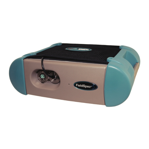
TerraSpec® User Manual
ASD Document 600541 Rev. G
© 2008 by ASD Inc.
www.asdi.com

ASD Document 600541 Rev. G ii TerraSpec® User Manual
www.asdi.com
Trademark Information
ASD Inc.
2555 55th Street
Boulder, CO 80301 USA
Phone: (303) 444-6522
www.asdi.com
FieldSpec®, LabSpec®, QualitySpec®, TerraSpec®, AgriSpec®, RxSpec®,
ViewSpec™, RS3™, Indico™, and goLab™ are registered, and unregistered
trademarks, and the intellectual property of ASD Inc. All trademarks used or
displayed in this document are the property of ASD, its affiliates, or third
party owners. Unauthorized use of these trademarks is illegal and punishable
by law. Nothing contained in this document is to be construed as granting, by
implication, estoppel, or otherwise, any license or right of use of any such
trademark without the prior and express written permission of ASD, or such
third party owner.
This document contains proprietary information protected by copyright law
and may not be reproduced in any manner without the express written
approval of ASD Inc.
The information and specifications contained in this manual are subject to
change without notice. ASD Inc. shall not be held liable for technical,
editorial omissions, or errors made herein; nor for incidental or consequential
damages resulting from furnishing, performance, or use of this material.
Technical Support
If you have any questions or concerns, please contact ASD Inc. by phone, fax,
or email:
Phone: 303-444-6522 X-144
Fax: 303-444-6825
Web: www.asdi.com
ftp: ftp.asdi.com
Technical support is committed to providing you with a timely response to
your questions. We will work with you to provide solutions to your
applications. Technical support is available to answer your questions Monday
thru Friday, 8 am to 5 pm Mountain Standard Time. We will happily respond
to your e-mail queries as well.

© 2007 ASD Inc. iii TerraSpec® User Manual
Table of Contents
Trademark Information . . . . . . . . . . . . . . . . . . . . . . . . . . . . . . . . . . . . . . . . . . . ii
Technical Support . . . . . . . . . . . . . . . . . . . . . . . . . . . . . . . . . . . . . . . . . . . . . . . ii
Declaration of Conformity . . . . . . . . . . . . . . . . . . . . . . . . . . . . . . . . . . . . . . . . vii
Chapter 1 Introduction . . . . . . . . . . . . . . . . . . . . . . . . . . . . . . . . . . . . . . . . . . . . . . . . . . . . 1
Hardware Specifications. . . . . . . . . . . . . . . . . . . . . . . . . . . . . . . . . . . . . . . . . 2
Physical Specifications . . . . . . . . . . . . . . . . . . . . . . . . . . . . . . . . . . . . . . . 2
Power Input and Output . . . . . . . . . . . . . . . . . . . . . . . . . . . . . . . . . . . . . . 2
TerraSpec Wavelength Configuration. . . . . . . . . . . . . . . . . . . . . . . . . . . . 3
Interface Requirement . . . . . . . . . . . . . . . . . . . . . . . . . . . . . . . . . . . . . . . 4
Standard Accessories. . . . . . . . . . . . . . . . . . . . . . . . . . . . . . . . . . . . . . . . 4
Computer Requirements . . . . . . . . . . . . . . . . . . . . . . . . . . . . . . . . . . . . . . . . 5
Software Requirement . . . . . . . . . . . . . . . . . . . . . . . . . . . . . . . . . . . . . . . . . . 5
Theory of Operation . . . . . . . . . . . . . . . . . . . . . . . . . . . . . . . . . . . . . . . . . . . . 6
Chapter 2 Setup . . . . . . . . . . . . . . . . . . . . . . . . . . . . . . . . . . . . . . . . . . . . . . . . . . . . . . . . . 11
Unpacking the Instrument. . . . . . . . . . . . . . . . . . . . . . . . . . . . . . . . . . . . . . . 12
Power Supply . . . . . . . . . . . . . . . . . . . . . . . . . . . . . . . . . . . . . . . . . . . . . . . . 13
Ethernet Cables . . . . . . . . . . . . . . . . . . . . . . . . . . . . . . . . . . . . . . . . . . . . . . 15
Accessory Power Port . . . . . . . . . . . . . . . . . . . . . . . . . . . . . . . . . . . . . . . . . 16
Remote Trigger. . . . . . . . . . . . . . . . . . . . . . . . . . . . . . . . . . . . . . . . . . . . . . . 17
Chapter 3 Usage and Maintenance . . . . . . . . . . . . . . . . . . . . . . . . . . . . . . . . . . . . . . . . . 19
Light Sources . . . . . . . . . . . . . . . . . . . . . . . . . . . . . . . . . . . . . . . . . . . . . . . . 19
Access and Ventilation . . . . . . . . . . . . . . . . . . . . . . . . . . . . . . . . . . . . . . . . . 19
Cleaning . . . . . . . . . . . . . . . . . . . . . . . . . . . . . . . . . . . . . . . . . . . . . . . . . . . . 20
Annual Maintenance. . . . . . . . . . . . . . . . . . . . . . . . . . . . . . . . . . . . . . . . . . . 20
Returning Instrument to ASD for Service . . . . . . . . . . . . . . . . . . . . . . . . . . . 20
Chapter 4 Fiber Optic Interface . . . . . . . . . . . . . . . . . . . . . . . . . . . . . . . . . . . . . . . . . . . . 21
Fiber Optic Cables . . . . . . . . . . . . . . . . . . . . . . . . . . . . . . . . . . . . . . . . . . . . 21
Fiber Optic Cable Interface. . . . . . . . . . . . . . . . . . . . . . . . . . . . . . . . . . . . . . 22
Matching Fiber Bundles . . . . . . . . . . . . . . . . . . . . . . . . . . . . . . . . . . . . . . . . 24
LED Check for Fiber Optic Cable. . . . . . . . . . . . . . . . . . . . . . . . . . . . . . . . . 26

ASD Document 600541 Rev. G iv TerraSpec® User Manual
www.asdi.com
Chapter 5 Batteries . . . . . . . . . . . . . . . . . . . . . . . . . . . . . . . . . . . . . . . . . . . . . . . . . . . . . . 31
Battery Care . . . . . . . . . . . . . . . . . . . . . . . . . . . . . . . . . . . . . . . . . . . . . . . . . 31
Battery Charger . . . . . . . . . . . . . . . . . . . . . . . . . . . . . . . . . . . . . . . . . . . . . . 32
Application Battery Indicator. . . . . . . . . . . . . . . . . . . . . . . . . . . . . . . . . . . . . 33
Chapter 6 Field Measurements. . . . . . . . . . . . . . . . . . . . . . . . . . . . . . . . . . . . . . . . . . . . . 35
Illumination . . . . . . . . . . . . . . . . . . . . . . . . . . . . . . . . . . . . . . . . . . . . . . . . . . 36
Rocks, Soils, and Man-Made Materials . . . . . . . . . . . . . . . . . . . . . . . . . . . . 36
Suggested Set-up. . . . . . . . . . . . . . . . . . . . . . . . . . . . . . . . . . . . . . . . . . . . . 36
RS3 Application . . . . . . . . . . . . . . . . . . . . . . . . . . . . . . . . . . . . . . . . . . . 36
Indico Application . . . . . . . . . . . . . . . . . . . . . . . . . . . . . . . . . . . . . . . . . . 37
White Reference. . . . . . . . . . . . . . . . . . . . . . . . . . . . . . . . . . . . . . . . . . . . . . 38
Spectralon Reflectance Data . . . . . . . . . . . . . . . . . . . . . . . . . . . . . . . . . 39
Maintaining Spectralon References . . . . . . . . . . . . . . . . . . . . . . . . . . . . 40
White Reference Procedures . . . . . . . . . . . . . . . . . . . . . . . . . . . . . . . . . 41
Appendix A Troubleshooting . . . . . . . . . . . . . . . . . . . . . . . . . . . . . . . . . . . . . . . . . . . . . . . . 43
Common Communication Fixes . . . . . . . . . . . . . . . . . . . . . . . . . . . . . . . . . . 43
Does Not Connect to the Spectrometer . . . . . . . . . . . . . . . . . . . . . . . . . . . . 43
Does Not Connect Wireless . . . . . . . . . . . . . . . . . . . . . . . . . . . . . . . . . . . . . 45
Does Not Connect to the Access Point . . . . . . . . . . . . . . . . . . . . . . . . . . . . 46
Spectrometer Loses its Wireless Connection. . . . . . . . . . . . . . . . . . . . . . . . 47
Wireless Interface is Disabled in the Netcfg Application . . . . . . . . . . . . . . . 47
Appendix B Reference Information . . . . . . . . . . . . . . . . . . . . . . . . . . . . . . . . . . . . . . . . . . . 49
Frequently Asked Questions (FAQ) . . . . . . . . . . . . . . . . . . . . . . . . . . . . . . . 49
What is a spectrometer?. . . . . . . . . . . . . . . . . . . . . . . . . . . . . . . . . . . . . 49
What are the differences between the ASD spectrometers? . . . . . . . . . 50
What is remote sensing? . . . . . . . . . . . . . . . . . . . . . . . . . . . . . . . . . . . . 50
How often do I need to optimize?. . . . . . . . . . . . . . . . . . . . . . . . . . . . . . 51
How often do I need a (baseline) White Reference? . . . . . . . . . . . . . . . 51
What spectrum average (or sample count) should I use? . . . . . . . . . . . 51
What if I want to keep the same settings all day? . . . . . . . . . . . . . . . . . 51
What are the units of radiance? . . . . . . . . . . . . . . . . . . . . . . . . . . . . . . . 52
Can I post-process my data? . . . . . . . . . . . . . . . . . . . . . . . . . . . . . . . . . 52
Why do I see oscillations (sine wave) in my data?. . . . . . . . . . . . . . . . . 52
What are these upward or downward spikes in VNIR data? . . . . . . . . . 52
What are these steps in my data? . . . . . . . . . . . . . . . . . . . . . . . . . . . . . 53
What can cause more noise in my data from last time?. . . . . . . . . . . . . 53

ASD Document 600541 Rev. G v TerraSpec® User Manual
www.asdi.com
Why does the VNIR drop to zero after a Dark Current collection?. . . . . 54
How do I set up GPS? . . . . . . . . . . . . . . . . . . . . . . . . . . . . . . . . . . . . . . 54
What does a broken fiber mean? . . . . . . . . . . . . . . . . . . . . . . . . . . . . . . 55
How long is the battery life? . . . . . . . . . . . . . . . . . . . . . . . . . . . . . . . . . . 56
What type of Ethernet cable can I use for the static IP configuration?. . 56
Can I install additional software on the instrument controller? . . . . . . . . 56
Why does the software seem to do unexpected things? . . . . . . . . . . . . 57
How long does it take for the TerraSpec spectrometer to warm up? . . . 57
Where is my serial number?. . . . . . . . . . . . . . . . . . . . . . . . . . . . . . . . . . 57
Data Conversion. . . . . . . . . . . . . . . . . . . . . . . . . . . . . . . . . . . . . . . . . . . . . . 58
Gain and Offset . . . . . . . . . . . . . . . . . . . . . . . . . . . . . . . . . . . . . . . . . . . . . . 58
Optimization . . . . . . . . . . . . . . . . . . . . . . . . . . . . . . . . . . . . . . . . . . . . . . . . . 58
Spectrum Averaging (or Sample Count). . . . . . . . . . . . . . . . . . . . . . . . . . . . 59
Temperature Effects . . . . . . . . . . . . . . . . . . . . . . . . . . . . . . . . . . . . . . . . . . . 59
Technical Support. . . . . . . . . . . . . . . . . . . . . . . . . . . . . . . . . . . . . . . . . . . . . 59
W.E.E.E. Compliance. . . . . . . . . . . . . . . . . . . . . . . . . . . . . . . . . . . . . . . . . . 60
Index . . . . . . . . . . . . . . . . . . . . . . . . . . . . . . . . . . . . . . . . . . . . . . . . . . . . . . . . . 61

ASD Document 600541 Rev. G vi TerraSpec® User Manual
www.asdi.com

ASD Document 600541 Rev. G vii TerraSpec® User Manual
www.asdi.com
Declaration of Conformity
gg
Manufacturers Name: Analytical Spectral Devices, Incorporated.
Manufacturers Address: 5335 Sterling Drive, Suite A
Boulder, CO 80301
Phone: (303) 444 6522
European Contact: Your local Analytical Spectral Devices Representative.
Declares that the product(s)
Product Name: TerraSpec
Product Numbers Description Range (nm)
A100800 SWIR1 & SWIR2 High Resolution 1000-2500
A100810 Full Range (VNIR, SWIR1, & SWIR2) High
Resolution 350-2500
A100820 SWIR2 only 1800-2500
Conforms to the following EU Directives:
Safety: Low Voltage Directive, 72/23/EEC, as amended by 93/68/EEC
EMC: Electromagnetic Compatibility Directive, 89/336/EEC, as amended
by 93/68/EEC
Supplementary Information:
The product complies with the requirements of the following Harmonized Product Standards and
carries the CE-Marking accordingly:
EN 61010-1: 2001 Safety Requirements for Electrical Equipment for Measurement,
Control and Laboratory use
EN 61326-1: 2002 Class A, Electrical Equipment for Measurement, control and
Laboratory use – EMC requirements
Signature:
Title:
Date:

ASD Document 600541 Rev. G viii TerraSpec® User Manual
www.asdi.com
Symbols - Definitions
CAUTION: Risk of Danger. This is a personal danger warning.
Documentation must be consulted in all cases where this symbol is marked.
Failure to acknowledge these warnings could result in personal injury to the
user.
CAUTION: Risk of Electric Shock. This is a personal danger warning.
Documentation must be consulted in all cases where this symbol is marked.
Failure to acknowledge these warnings could result in personal injury to the
user.
CAUTION: Hot Surface. This is a personal danger warning.
Docuemntation must be consulted in all cases where this symbol is marked.
Failure to acknowledge these warnings could result in personal injury to the
user.
Recycle. Items with this symbol indicate that the item should be recycled and
not disposed of as general waste.
Warnings and cautions are placed throughout this manual for the convenience
of the reader. However, the absence of warnings and cautions do not preclude
the user of proper caution and handling. Usual precautions are recommended
to be taken at all times, either written or otherwise, to avoid personal injury or
damage to ASD equipment.

ASD Document 600541 Rev. G ix TerraSpec® User Manual
www.asdi.com
The Power Supply is intended for Indoor Use Only
When using an electrical appliance, basic safety precautions should always be
followed.
Danger- To reduce the risk of electric shock read all instructions before using
the power supply. A power supply should never be left unattended when
plugged in. Always unplug the power supply from the mains socket
immediately after using.
Warning- To reduce risk of burns, fire, electric shock or injury to persons or
animals:
1. Use this power supply only for its intended use as described below.
2. Do not use outdoors.
3. Do not allow to be used as a toy. Pay close attention when this power
supply is used by, or near to, children.
4. Use only attachments recommended by the manufacturer.
5. Never operate the power supply if it has a damaged cord or plug, if it has
been dropped or damaged or if it has fallen into water. In such cases return the
power supply to an authorized dealer or service center for examination or
repair.
6. Never drop or insert an object into any openings.
7. Do not operate where aerosol (spray) products are being used or where
oxygen is being administered.
8. The power supply should be used near to a convenient and easily accessible
mains socket.

ASD Document 600541 Rev. G x TerraSpec® User Manual
www.asdi.com
Notes:

© 2007 ASD Inc. 1 TerraSpec® User Manual
Chapter 1 Introduction
The TerraSpec spectrometer is a high-resolution instrument that measures the
visible near-infrared (VNIR) and short-wave infrared (SWIR) spectra for
geologic remote sensing and analysis.
The TerraSpec spectrometer is specially designed for mining and geology
applications. It is ideally suited for performing reflectance and transmittance
spectral measurements of rocks, minerals, and core samples. Its higher
resolution is optimized for identification of minerals associated with
economic ore deposits.
The ASD Accessories Guide contains an array of devices to extend the
application areas for the spectrometer, the Hi-Brite MugLite and Hi-Brite
Contact Probe are specifically designed to work with this high resolution
instrument.
The TerraSpec spectrometer is compact and field portable. It has a spectral
range of 350-2500 nm and rapid data collection (10 spectra per second).
While its most highly regarded features are performance and field-portability,
these instruments perform competitively in the laboratory as well.
Features and Advantages
Accurate and Precise - high resolution and superior repeatability of
results for better discrimination and analysis of materials.
Rugged and Transportable - Resistant to vibration and changes in
temperature or humidity.
Fast - 10 spectra per second data collection for the entire 350-2500 nm range.
»0.1second scanning time provides an accurate average every second
» Users can quickly scan several areas when analyzing bulk samples.
» Rapid analysis allows screening all or most samples versus spot
checking.
Compatible - Works with off-the-shelf mineral spectrum analysis software
available from SII and chemometrics software (such as Grams™ PLS
plus/IQ and Unscrambler®).

ASD Document 600541 Rev. G 2 TerraSpec® User Manual
www.asdi.com Chapter 1 Introduction
1.1 Hardware Specifications
This section contains details about the TerraSpec spectrometer.
1.1.1 Physical Specifications
•Durable satin powder coat finish with orange urethane end-caps and
handles
• All vital components are in a dust-proof enclosure and EMI sealed
•Adjustable fiber optic to instrument spacer
1.1.2 Power Input and Output
Height 12.7 cm 5 inches
Width 35.6 cm 14.5 inches
Depth 29.2 cm 11.5 inches
Weight 5.6 kg 12 lbs
AC Power Supply Type Auto ranging, Switching, SELV
AC Input 90-240 VAC, 50/60 Hz
DC Input +12 VDC, 60 W
Accessory Power Port
(front of instrument) Output, +12 VDC, 19.2 W (max).

ASD Document 600541 Rev. G 3 TerraSpec® User Manual
www.asdi.com Chapter 1 Introduction
1.1.3 TerraSpec Wavelength Configuration
The near infrared (NIR) is also called the short-wave infrared (SWIR).
The spectral resolution is:
•3nm (Full-Width-Half-Maximum) at 700 nm.
• 6 nm (Full-Width-Half-Maximum) at 1400 nm.
•6nm (Full-Width-Half-Maximum) at 2100 nm.
The sampling interval is:
•1.4nm for the spectral region 350-1000 nm.
•2nm for the spectral region 1000-2500 nm.
The TerraSpec spectrometer may be configured to have three separate
holographic diffraction gratings with three separate detectors. Each detector is
also covered with the appropriate order separation filters to eliminate second
and higher order light.
•VNIR: 512 element silicon photo-diode array for the spectral region
350-1000 nm.
• SWIR1: graded index, TE-cooled, extended range, InGaAs, photo-diode
for the spectral region 1000 nm to 1800 nm.
• SWIR2: graded index, TE-cooled, extended range, InGaAs, photo-diode
for the spectral region 1800 nm to 2500 nm.
Instrument Configuration Power Rating Maximum
350-1050 nm 12 VDC, 45 Watt
350-1800 nm 12 VDC, 50 Watt
1000-1800 nm 12 VDC, 50 Watt
1800-2500 nm 12 VDC, 50 Watt
1000-2500 nm 12 VDC, 60 Watt
350-2500 nm 12 VDC, 60 Watt
Wavelength Name Wavelength Range
VNIR-SWIR1-SWIR2 350-2500 nm
SWIR1-SWIR2 1000-2500 nm
SWIR2 only 1800-2500 nm

ASD Document 600541 Rev. G 4 TerraSpec® User Manual
www.asdi.com Chapter 1 Introduction
1.1.4 Interface Requirement
The TerraSpec spectrometer has 10/100 Base T Ethernet port. The
spectrometer with an Ethernet cross-over cable can be directly connected to
the Ethernet port provided on many laptop computers.
The TerraSpec spectrometer can communicate with the instrument controller
using an optional 802.11b wireless card. If the instrument controller is
supplied by the customer, it must be 802.11b compatible.
The TerraSpec spectrometer uses industry standard components. The
instrument controller has the same general connection speed and distance
capabilities as other 802.11b wireless devices.
For the best performance, ensure a clear line-of-sight between the
spectrometer and instrument controller. Obstructions or radio frequency
interference in close proximity can cause loss of communication or
significantly shorten the communication range.
Note: For information about configuration of the Ethernet card and cable, please
refer to the Installation Manual.
1.1.5 Standard Accessories
• TerraSpec® Spectrometer
• TerraSpec® User Manual (PDF on Flash Drive)
•Instrument Controller: ASD-approved laptop computer
•RS3Software Pack
•1.5 meter FR Low OH Fiber Optic Jumper Cable
•Power Supply 12 V
•Battery Belt, Gel Cell (12 V, 9 A hour) with Charger and 6 ft.
Battery-to-Instrument Power Cable
•Power Adapter with 6 m (20 ft) Cable for Automobile Cigarette Lighter
(When using this adapter, turn off the engine to the vehicle,
electromagnetic fields from the engine can generate noise in the acquired
signals.)
•1.5meter Instrument-to-Probe Accessory Power Cable
• Remote Trigger with LEDs and Velcro Pads
•RJ45 CAT 5e UTP Ethernet, Shielded, Crossover Cable
•64MB (min.) Flash Drive Memory USB Flash Drive
• Mylar Wavelength Reference
•Shipping Trunk: Durable, air tight, wheeled, fold down handle, and foam
filled with cutouts to protect the instrument and many accessories

ASD Document 600541 Rev. G 5 TerraSpec® User Manual
www.asdi.com Chapter 1 Introduction
1.2 Computer Requirements
The instrument controller is a computer that manages the TerraSpec
spectrometer, stores data, and processes the results.
The standard TerraSpec spectrometer includes a laptop computer, or the
instrument controller.
The minimum requirements for the instrument controller are:
•1.2GHz Pentium or better notebook or PC-w/monitor
•256MB RAM or more
•20GB of free disk space
• 1024 x 768 or better graphics resolution
• 24-bit color or better - 32-bit recommended
•Ethernet port: 10/100 Base T Ethernet interface
•(Optional) Ethernet wireless (WiFi) adaptor: PCMIA, USB, or built-in
that is compatible with the 802.11b standard
•(Optional) Serial communications port (or USB port) for GPS receiver.
(only required when GPS is used)
• (Optional) NMEA compatible GPS receiver
1.3 Software Requirement
The instrument controller requires the following software:
•RS3Software from ASD
•Microsoft Windows® 95/98/NT/2000/ME/XP Operating System
• Microsoft Internet Explorer 6.0 or better
Users need a basic understanding of the Microsoft Windows operating system
including software installation.
International customers using non-English versions of Windows must alter
the Regional Settings under Start->Settings->Control Panel. The
default language must be set to English (United States) in order for the
software to be registered and operate correctly. The numbering format must
also be set to English.

ASD Document 600541 Rev. G 6 TerraSpec® User Manual
www.asdi.com Chapter 1 Introduction
1.4 Theory of Operation
The TerraSpec spectrometer measures the optical energy that is reflected by,
absorbed into, or transmitted through a sample. Optical energy refers to a
wavelength range that is greater than just the visible wavelengths, and is
sometimes called electromagnetic radiation or optical radiation.
With accessories, various set-ups, and built-in processing of the optical
energy signal, the TerraSpec spectrometer can measure:
• spectral reflectance,
• spectral transmittance, and
• spectral absorbance.
Fiber Optic Collection of Reflected/Transmitted Light
Optical energy is collected through a bundle of specially formulated optical
fibers, precisely cut, polished, and sealed for extremely efficient energy
collection. The fibers themselves are of low OH composition providing the
maximum transmission available across the instrument's wavelength range.
Inside the TerraSpec® Spectrometer
The fiber cable delivers the collected optical energy into the instrument,
where it is projected onto a holographic diffraction grating. The grating
separates and reflects the wavelength components for independent
measurement by the detectors.
Visible/Near-Infrared (VNIR)
The Visible/Near-Infrared (VNIR: 350-1000 nm wavelength) portion of the
spectrum is measured by a 512-channel silicon photodiode array overlaid with
an order separation filter. Each channel (or detector) is geometrically
positioned to receive light within a narrow (1.4 nm) range. The VNIR
spectrometer has a spectral resolution (full-width half maximum of a single
emission line) of approximately 3 nm at around 700 nm.
Each detector converts incident photons into electrons. This photocurrent is
continually converted to a voltage and is then periodically digitized by a
16-bit analog-to-digital (A/D) converter. This digitized spectral data is then
transmitted to the instrument controller for further processing and analysis by
the controlling software.
The 512-channel array permits the entire VNIR spectrum to be scanned in
parallel at 1.4 nm wavelength intervals. A single sample can be acquired in as
little as 17 ms.

ASD Document 600541 Rev. G 7 TerraSpec® User Manual
www.asdi.com Chapter 1 Introduction
Short-Wave Infrared (SWIR)
The Near-Infrared (NIR), also called Short-Wave Infrared (SWIR), portion of
the spectrum is acquired with two scanning spectrometers:
•SWIR1 for the wavelength range of 1000 nm to 1800 nm.
• SWIR2 for the wavelength range of 1800 nm to 2500 nm.
The SWIR scanning spectrometers only have one detector for SWIR1 and
another for SWIR2. This is different from the VNIR spectrometer, which has
an array of 512 detectors. Thus, SWIR spectrometers collect wavelength
information sequentially rather than in parallel.
Each SWIR spectrometer consists of a concave holographic grating and a
single thermo-electrically cooled Indium Gallium Arsenide (InGaAs)
detector. The gratings are mounted about a common shaft which oscillates
back and forth through a 15 degree swing. As the grating moves, it exposes
the SWIR1 and SWIR2 detectors to different wavelengths of optical energy.
Each SWIR spectrometer has ~600 channels, or ~2 nm sampling interval per
SWIR channel. The spectrometer firmware automatically compensates for the
overlap in wavelength intervals.
Like the VNIR detectors, the SWIR1 and SWIR2 detectors convert incident
photons into electrons. This photocurrent is continually converted to a voltage
and is then periodically digitized by a 16-bit analog-to-digital (A/D)
converter. This digitized spectral data is then transmitted to the instrument
controller for further processing and analysis by the controlling software.
The grating is physically oscillating with a period of 200 ms. It performs a
forward scan and a backward scan, resulting in 100 ms per scan. This is the
minimum time required for any SWIR samples, or full-range samples.
Communicating with the Instrument Controller (Computer)
The TerraSpec spectrometer communicates with the instrument controller
using a cross-over Ethernet cable or optional Wireless Ethernet (WiFi)
interface. The amount of data that is sent depends on the configuration of the
spectrometer.
•A single sample of VNIR is ~1024 bytes.
• A single sample of SWIR1 is ~2400 bytes.
• A single sample of SWIR2 is ~2400 bytes.
A full-range TerraSpec spectrometer can create packet data sizes over 5 KB.
Other single or dual range configurations of the spectrometer create smaller
data packets (adding the packet sizes as above.)
When features for spectrum averaging (or sample count) are turned on within
the application software on the instrument controller, the averaging is
performed at the spectrometer.

ASD Document 600541 Rev. G 8 TerraSpec® User Manual
www.asdi.com Chapter 1 Introduction
Dark Current Measurement
Dark Current (DC) refers to current generated within a detector in the absence
of any external photons. DC is the amount of electrical current that is inherent
in the spectrometer’s detectors and other electrical components and is additive
to the signal generated by the measured external optical radiation.
Note: Noise is the uncertainty in a given measurement, one channel at a time. Noise
by definition is random. Noise can be reduced by using more samples and
averaging the signal. Dark Current is different from noise, because it is
relatively stable and can be characterized.
This manual uses DC to refer to all systematic contributions to the detector’s
signal. DC is a property of the detector and the associated electronics (not the
light source). DC varies with temperature. In the VNIR region, DC also varies
with integration time.
Whenever DC is taken, a mechanical shutter is used to block off the entrance
slit of the VNIR spectrometer so the signal can be measured. This signal is
subtracted from each subsequent spectrum until another DC is taken. The
SWIR spectrometers take and subtract DC on every scan.
The DC measurement can be updated at any time, but should be updated more
frequently in the beginning of a given session while the instrument warms up.
The VNIR spectrometer is fitted with a unique software and hardware
combination feature called Driftlock. Driftlock corrects for DC changes over
time. It automatically updates DC for every measurement by looking at a
series of masked pixels at the front portion of the VNIR array. The Driftlock
feature corrects for the majority of DC variation over time.
White Reference
A material with approximately 100% reflectance across the entire spectrum is
called a white reference panel or white reference standard.
The raw measurement made by the spectrometer is influenced by both the
sample and the light source. An independent measure of the light source
illumination on a reference of known reflectance is required to calculate the
reflectance of the sample. The use of a white reference standard with near
100% reflectance simplifies this calculation.
Reflectance and transmittance are inherent properties of all materials and are
independent of the light source.
Reflectance is the ratio of energy reflected from a sample to the energy
incident on the sample. Spectral Reflectance is the reflectance as a
function of wavelength.
Transmittance is the ratio of the radiant energy transmitted through a sample
to the radiant energy incident on the surface of the sample. Spectral
Transmittance is the transmittance as a function of wavelength.

ASD Document 600541 Rev. G 9 TerraSpec® User Manual
www.asdi.com Chapter 1 Introduction
Relative reflectance is computed by dividing the energy reflected from the
sample by the energy reflected off a white reference panel or standard.
Accessories for Light Sources and Probes
ASD offers several accessories for:
• Delivering illumination to the sample
• Collecting reflected or transmitted light from the sample
•Transmitting the collected light to the spectrometer
Some accessories, such as the Hi-Brite Contact Probe, perform all of these
functions. Other accessories, such as some of the optional foreoptic probes,
rely on other illumination sources.
Accurate analysis of collected spectra requires an adequate level of incident
light on the sample. The Hi-Brite Contact Probe accessory is designed for
stability and accuracy and provides a controlled source of incident light
having a color temperature of 3,000°K. The probe is powered by the
accessory power port of the TerraSpec spectrometer. Characteristics of the
light source are eliminated when the white reference (or baseline spectrum) is
applied to each raw sample spectrum.

ASD Document 600541 Rev. G 10 TerraSpec® User Manual
www.asdi.com Chapter 1 Introduction
Notes:
This manual suits for next models
3
Table of contents
Other ASD Measuring Instrument manuals
Popular Measuring Instrument manuals by other brands

Lumel
Lumel N30U User Manual & Quick Start

Rohde & Schwarz
Rohde & Schwarz EVSG1000 Getting started

PCB Piezotronics
PCB Piezotronics IMI SENSORS ICP 629A31 Installation and operating manual

Bosch
Bosch GLL 30 G Original instructions

Fluidwell
Fluidwell F127-P-EL-TA manual

Ametek
Ametek LAND SPOT+ Series user guide