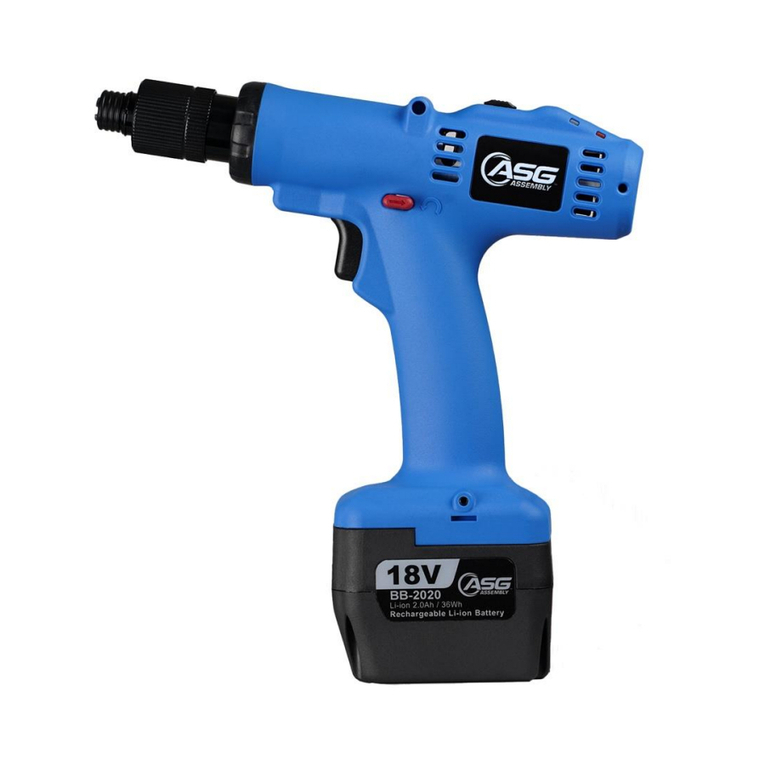
ASG TLB-D412LH User manual

ASG, Division of Jergens, Inc.
15700 S. Waterloo Road | Cleveland, OH 44110-3898 | Phone: (888) 486-6163 | Fax: (216) 481-4519 | Email: asginfo@asg-jergens.com | Web: www.asg-jergens.com | Revision Date: 01/03/18 1
Table of Contents
Overview ................................................................................................................. 1
General Safety Rules................................................................................................ 2
Safety Instructions ................................................................................................... 3
Description of Operation.......................................................................................... 3
Grounding Instructions ............................................................................................ 3
Installation Instructions ........................................................................................... 4
Panel Specications ................................................................................................. 4
Counting Set-Up Instructions ................................................................................... 5
Torque Adjustment Operation .................................................................................. 8
Servicing .................................................................................................................. 8
Product Specications ............................................................................................. 9
Warranty .................................................................................................................. 9
Overview
Thank you very much for selecting the TLB-D Brushless Electric Screwdriver.
Read this manual before placing tool in service or operation. Save
these instructions for future reference. It is the responsibility of the
employer to place the information in this manual into the hands of
the operator. Failure to observe the following warnings could result
in injury. When using electric tools, basic safety precautions should
always be followed to reduce the risk of re, electric shock, and
personal injury.
Note: ASG is not responsible for customer modication of tools for applications on
which ASG was not consulted.
• Read these instructions for the proper use of the tool.
• After having read these instructions, keep them in a convenient place so you or
the operator can refer to them whenever necessary.
TLB-D Brushless Electric Screwdrivers
PLEASE NOTE: When repairing or replacing tools or components on any TLB
Series purchased in 2016 or prior, please contact ASG representative

ASG, Division of Jergens, Inc.
15700 S. Waterloo Road | Cleveland, OH 44110-3898 | Phone: (888) 486-6163 | Fax: (216) 481-4519 | Email: asginfo@asg-jergens.com | Web: www.asg-jergens.com | Revision Date: 01/03/18 2
General Safety Rules
Electrical Safety
• Keep work area clean and well lit.
• Electric screwdriver plugs must match the outlet. Never modify the plug in any
way. Do not use any adapter plugs with earthed (grounded) electric screwdrivers.
These precautions will reduce the risk of electric shock.
• Don’t expose an electric screwdriver to rain or wet conditions as this will increase
the risk of electric shock.
• Never use the cord to carry, pull, or unplug the electric screwdriver. Keep cord
away from heat, oil, sharp edges or moving parts. Damaged or entangled cords
increase the risk of electric shock.
Personal Safety
• Stay alert and pay attention to your surroundings when operating an electric
screwdriver. Do not use an electric screwdriver while you are tired or under the
inuence of drugs, alcohol, or medication, as this could result in serious personal
injury.
• Ensure the switch is in the off position before plugging in to avoid accidental
starting.
• Keep proper footing and balance at all times.
Electrical Screwdriver Use and Care
• Use the correct electric screwdriver and power supply for your application.
• Do not use an electric screwdriver if the switch is broken. Any electric screwdriver
that cannot be controlled with the switch is dangerous and must be repaired.
• Disconnect the plug from the power source before making any adjustments,
changing accessories, or storing the electric screwdriver. Such preventive safety
measures reduce the risk of starting the electric screwdriver accidentally.
• Keep out of reach of children and untrained personnel. Electric screwdrivers are
dangerous in the hands of untrained users.
General Safety Rules (Continued)
Service
• Have your electric screwdriver serviced by ASG. This will ensure that the safety and
quality of the electric screwdriver is maintained.

ASG, Division of Jergens, Inc.
15700 S. Waterloo Road | Cleveland, OH 44110-3898 | Phone: (888) 486-6163 | Fax: (216) 481-4519 | Email: asginfo@asg-jergens.com | Web: www.asg-jergens.com | Revision Date: 01/03/18 3
Safety Instructions
• Make sure the switch is in the OFF position and tool is unplugged when changing
a bit
• Do not allow chemicals such as acetone, benzene, thinner, trichloroethylene
ketone, or other similar chemicals to come in contact with the screwdriver housing
as damage will result.
• Do not drop or misuse the screwdriver.
• Do not adjust the torque setting higher than 8 on the torque scale.
• There should be a tool rest interval for cycles of three seconds or longer. This tool
is intended for a duty cycle of 0.8 seconds on, 3.2 seconds off.
• Do not tighten more than 800 tapping screws (size: 3mm. Length: 5mm) per hour.
• Do not use this screwdriver for tightening wood screws.
• Do not operate the Forward/Reverse Switch while the motor is running.
• Turn the switch to the OFF position and unplug the screwdriver when the tool is
not in use
• Always grasp the plug of the power cord when plugging in/unplugging.
• Always secure the power supply to avoid movement.
• If the power supply overheats or is overloaded with maximum current rating, the
high-speed fuse will cut off the power. If this situation continues, stop operation
immediately and contact ASG for repair.
• Do not disassemble the electric screwdriver or try to repair it yourself.
• When power supply is not in use, please turn the main power switch OFF and
unplug the power supply.
Description of Operation
Inserting/Removing Bit and Bit Type
• Push up the holder clamp to unlock it. Thus, the bit can be freely attached and
detached.
• Insert the power plug into a receptacle and set the switch to “F” (forward
position)
• Apply the bit to the screw head and either press the lever or push to start the
tool. The switch will be turned ON to start the motor running.
• When the screw is tightened and reaches the torque that you had set, the tool
will stop automatically.
• To reverse the screw, set the changeover switch to “R” (reverse position).
Do not operate this tool without protective earth connected
Grounding Instructions
The tool should be grounded while in use to protect the operator from electric shock.
The tool is equipped with a three-conductor cord and three-prong grounding-type plug
to t the proper grounding-type receptacle. The green (or green and yellow) conductor
in the cord is the grounding wire. Never connect the green (or green and yellow)
wire to a live terminal.
Green and Yellow Earth
Blue Neutral
Brown Live
ASG, Division of Jergens, Inc.
15700 S. Waterloo Road | Cleveland, OH 44110-3898 | Phone: (888) 486-6163 | Fax: (216) 481-4519 | Email: asginfo@asg-jergens.com | Web: www.asg-jergens.com | Revision Date: 01/03/18 4
Installation Instructions
• Use the power supply voltage recommended in the specication of this manual.
• When using a commercial power supply be sure to set up circuit and safety
breakers.You must also properly ground the mechanisms.
• The temperature and humidity should be kept at appropriate levels.
• Do not set up the power supply in a room that has poor ventilation and where it
may be exposed to dust and metallic particles.
• Do not put anything on top of power supply
• Attach the power supply securely to a at, stable surface.
• Do not permit unauthorized personnel to operate this power supply.
• Do not set up the power supply near any high voltage machinery
• Avoid setting up or storing the power supply in wet or oily environments or where
it might be exposed to corrosive or ammable gases.
Panel Specications
No. Name Function
1 3-Colored Light To show operation is OK, NG, or the mode condition
2 Panel To show set value, set screws number and other value
3 Power Switch Push ve seconds: to disable COUNTING FUNCTION CLEAR Push
three seconds: CLEAR
4 SELECT key Push three seconds: Enter the selection
5 Up Key When entering the selection, this key increases value
6 Down Key When entering the selection, this key decreases value
7 Reset Restore to factory settings
S+P Automatic learning
UP+P Waiting time mode
UP+DOWN Buzzer mode
S+UP If press together to enable P/R/S button, and then press again to
disable P/R/S button

ASG, Division of Jergens, Inc.
15700 S. Waterloo Road | Cleveland, OH 44110-3898 | Phone: (888) 486-6163 | Fax: (216) 481-4519 | Email: asginfo@asg-jergens.com | Web: www.asg-jergens.com | Revision Date: 01/03/18 5
Counting Set-Up Instructions
Push three seconds to enter the selection ) SL===SC===At===Ht===Lt===LL===Ns===Rn===Rt <Conrm>
Function Name Set-Up Time and Value Description Buzz Time/Light Factory Default Settings
SL 01-05/UU Screw List --- ---
SC 1-99 Counting number / count-down only --- 05
At 0.1-9.9 Automatic zero time / Signal output time --- 1.0
Ht 0.1-9.9 Ht time Stop time can be used to check
for stripped screws
Five buzz and LED red ash 2.0
Lt 0.01-9.9 Lt time will show early shutoff Two buzz and LED red ash 0.00
LL 0.01-9.9 Reconrm time after fastening --- 0.00
Ns Y or N Ns: Set the function of stopping the
screwdriver when any error message
occurs.
Y: Stop the screwdriver when any error
occurred meanwhile, Reverse is OK;
Restore by pressing “S” button
N: screwdriver could operate continually
when any error occurred.
Rn Y or N Rn: Set the count-up mode for reverse
Y: Count for each reverse;
N: Only count once when reverse
Rt 0.01 – 9.99 Rt: Set auto reverse time after the
screwdriver shuts off.
Backward to Count-Up 1 COUNT When screwdriver is in reverse, the
counter will subtract count
--- ---
LC --- Keypad LOCK P/S/R button
UN --- UNLOCK
Ln --- Automatic learning. LED keeps ash of light ---

ASG, Division of Jergens, Inc.
15700 S. Waterloo Road | Cleveland, OH 44110-3898 | Phone: (888) 486-6163 | Fax: (216) 481-4519 | Email: asginfo@asg-jergens.com | Web: www.asg-jergens.com | Revision Date: 01/03/18 6
Counting Set-Up Instructions (Continued)
• In the set-up, if Lt and LL show “02.”it means 0.02, push P to adjust decimal.
• During operation, LED will show three colors: OK is green light; NG is red light; standby learning is orange light.
• EA-BD PCB has three kinds of signal, OUTPUT OK1, OKALL and NG
• Output users need input voltage to drive the buzzer, the input voltage can’t be over DC24V 10mA.
• There is a new function in the screwdriver that will judge a NG if there is a start signal and it is OFF before Lt.
Function Name Set-Up Time and Value Description Buzz Time/Light Factory Default Settings
Buzzer En Wrong Set-Up --- Wrong Set-Up, such as Lt>Ht Three buzz and LED red ash.Automati-
cally show En
---
dt Standby time Seconds Buzz if set-number of screws are not
completed in the allotted set time for each
screw fastening
Lasting buzz s and LED red ash ---
Tt Working time for
a set of screwdriver
Minutes Buzz if set-number of screws are not
completed in the allotted set time for a
set screw fastening
Lasting buzz s and LED red ash

ASG, Division of Jergens, Inc.
15700 S. Waterloo Road | Cleveland, OH 44110-3898 | Phone: (888) 486-6163 | Fax: (216) 481-4519 | Email: asginfo@asg-jergens.com | Web: www.asg-jergens.com | Revision Date: 01/03/18 7
Counting Set-Up Instructions (Continued)
Push both UP+DOWN set up the buzzer:
Ht/Lt Description:
• Ht/Lt sets up the period of time. If the tool stops within the set period, it means
OK. In contrast, it will be (NG) if it stops before Lt or after Ht. The LT accepts 0.00,
but it can be increased or decreased in SELECT.
• To shut down the count: If count needs be shut down, push P key for ve seconds
until no gures on the panel, meanwhile LED 1 will show green light.
• If set value need be reset during counting, push for three seconds.
ON Fastening a screw, completing work and mistaken operation, buzzer
will be on.
OFF Wrong operation will be buzzed.
FF Work completed and wrong operation will cause buzz.
EF As one screw is fastened and work is completed, buzzer will be on; as
mistake made has no buzz.
Counting Set-Up Instructions (Continued)
• Simulated-learning: While electric screwdriver is not used, push S key and then
push P key to enter simulated-learning procedure; SL(S)===SC(S)===At(S)===
Test Data===(P)
1. Show SL (Screw List), select UP/DOWN to change number and then push S
(conrm)
2. Show SC (counting number), select UP/DOWN to change number and then push S
(conrm)
3. Show At (automatic zero), UP/DOWN to change value; then push P (conrm)
4. Enter simulated-learning (LED 1 will keep ash)
• LED light will ash in simulated-learning. Push P key to record value after
simulated –learning.
• UP and P key can set up waiting time.
• Push R key to restore to factory settings.
General Execution of Pre-Set Program
• If the screwdriver stop time is in the dotted line,
it is normal fastening. OK will be shown.
• If the screwdriver stop time is before Lt or over
Ht stop is before Ht or over Lt, it is NG.

ASG, Division of Jergens, Inc.
15700 S. Waterloo Road | Cleveland, OH 44110-3898 | Phone: (888) 486-6163 | Fax: (216) 481-4519 | Email: asginfo@asg-jergens.com | Web: www.asg-jergens.com | Revision Date: 01/03/18 8
Torque Adjustment Operation
• Determine the torque output of the tool with a torque tester such as the ASG DTT
or DTT-L.
• Increase or decrease the torque by rotating the Spring Adjusting Ring. Rotating
the ring clockwise to a higher number on the torque scale increases torque output
while rotating the ring counterclockwise to a lower number decreases the torque
output.
• Continue to check the adjustment with a torque tester until you are satised with
the torque output. If you are making nal torque adjustments on line, always start
below the desired torque and work upward.
• The torque scale on the tool goes from 0 to 8. Only the even numbers appear:
2,4,6, and 8. This is not the actual torque the tool is going to produce. The
numbers on the scale are only a point of reference.
Servicing
Maintenance and Inspection
• Do not use the tool more than 8 hours a day.
• Check for carbon brush wear. We recommend replacing the brushes based on
use.
• Do not let the motor and power supply get over heated. Do not run more than
10-15 screws/minute.
• If you use the tool more than 8 hours a day, have the tool evaluated for
preventative maintenance.
• Inspect tool cords periodically. If damaged, contact ASG.
• Do not remove any labels.
Using non-ASG replacement parts may result in decreased
tool performance and increased maintenance and may void all
warranties.
All repairs and maintenance of this tool must be performed by ASG
ASG is not responsible for customer modication of tools for
applications on which ASG was not consulted.
It is the responsibility of the employer to place the information in
this manual into the hands of the operator.
DO NOT ATTEMPT TO REPAIR THIS ELECTRIC SCREWDRIVER
SAVE THESE INSTRUCTIONS - DO NOT DESTROY

ASG, Division of Jergens, Inc.
15700 S. Waterloo Road | Cleveland, OH 44110-3898 | Phone: (888) 486-6163 | Fax: (216) 481-4519 | Email: asginfo@asg-jergens.com | Web: www.asg-jergens.com | Revision Date: 01/03/18 9
Product Specications
Warranty
The warranty is 1 year after delivery. If any troubles should occur, please contact ASG.
In the following cases, the purchaser shall pay for parts and labor regardless of the
terms of warranty:
• Failure due to improper handling.
• Failure due to product modication or improper processing.
• Failure due to causes beyond control (for example earthquake or re).
• Consumables, replaceable parts, and replacement work expenses.
Model Number ASG
Number Input Voltage Power
Consumption
Torque Torque Adjustment Weight Length Power Supply
lbf.in N.m HI LO lb g in. mm
TLB-D412LH 68602 DC 24V or 32V 55W 1.3 - 10.4 0.15 - 1.18 1000 700 1.3 600 10.7 273 TLB-PS61 (ASG #68634)
TLB-D419L 68623 DC 24V or 32V 55W 2.6 - 16.5 0.29 - 1.86 1000 700 1.3 600 10.7 273 TLB-PS61 (ASG #68634)
TLB-D412PH 68605 DC 24V or 32V 55W 1.8 - 10.4 0.2 - 1.18 2000 1400 1.3 600 10.8 275 TLB-PS61 (ASG #68634)
TLB-D630LH 68603 DC 40V 90W 8.7 - 26.0 0.98 - 2.94 2000 1500 1.9 840 11.9 303 TLB-PS801 (ASG #68638)
TLB-D630PH 68606 DC 40V 90W 8.7 - 26.0 0.98 - 2.94 2000 1500 1.9 840 12.0 306 TLB-PS801 (ASG #68638)
TLB-D650L 68604 DC 40V 120W 17.3 - 43.4 1.96 - 4.9 1000 750 1.9 840 11.9 303 TLB-PS801 (ASG #68638)
TLB-D650P 68607 DC 40V 120W 17.3 - 43.4 1.96 - 4.9 1000 750 1.9 840 12.0 306 TLB-PS801 (ASG #68638)
ESD Safe Models
TLB-D419L-ESD 68624 DC 24V or 32V 55W 2.6 - 16.5 0.29 - 1.86 1000 700 1.3 600 10.7 273 TLB-PS61 (ASG #68634)
PLEASE NOTE: When repairing or replacing tools or components on any TLB
Series purchased in 2016 or prior, please contact ASG representative
This manual suits for next models
7
Table of contents
Other ASG Power Screwdriver manuals