GT-P4.5XD
AIRSCREWDRIVER
INSTRUCTIONMANUAL
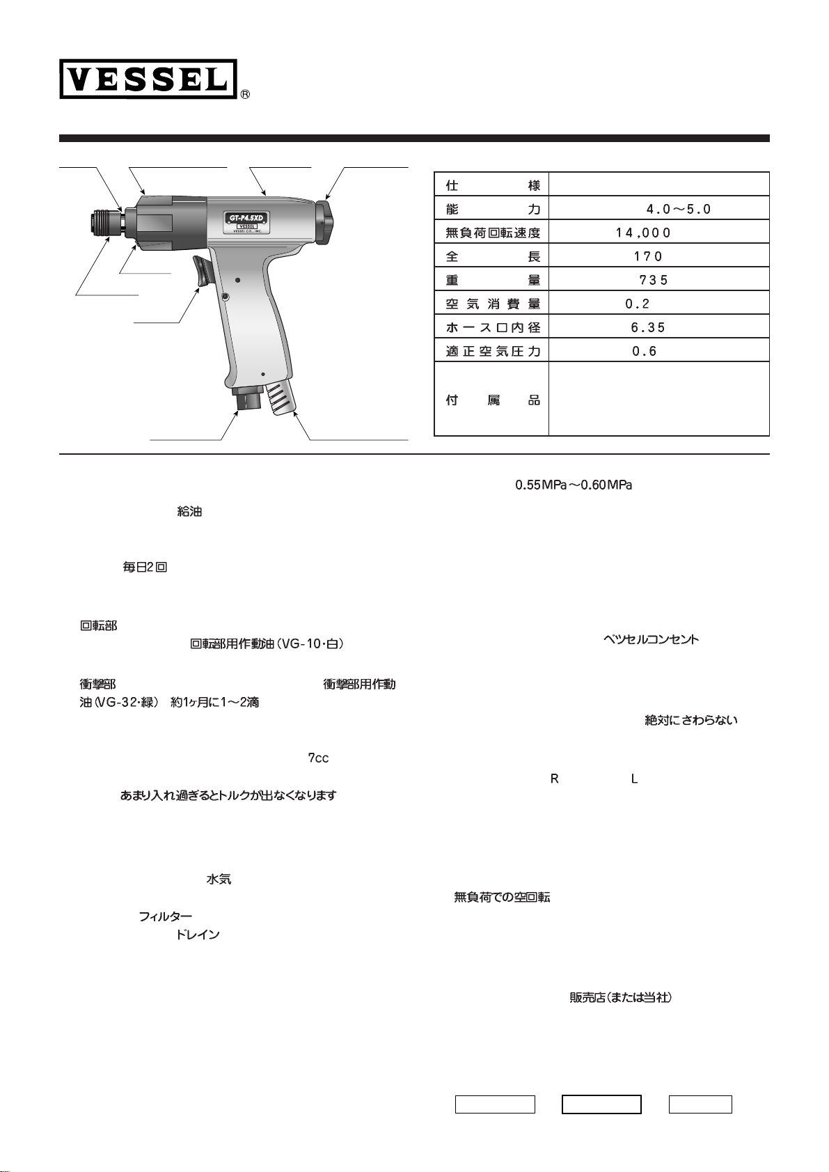
Model GT - P4.5XD
Capacity 4.0 - 5.0mm
Free Speed 14,000rpm
Overall Length 170mm
Weight 735g
Air Consumption 0.2m3/min
Inner Hose Diam. 6.35mm
Air Pressure 0.6MPa
Accessories Both End Bit (A14 +2x65G) 1PC
VESSEL Air Plug (BPB-2) 1PC
ISO VG-10 lubrication oil (Clear) 15cc
ISO VG-32 lubrication oil (Light Green) 15cc
1. Lubrication is indispensable to air tools.
It is necessary to install a lubricator for automatic
oil feed, but if it is not available, manual lubrication
twice a day is recommended for longer product life
and efficient function of its mechanism. The
package contains two different kinds of lubrication
oils.
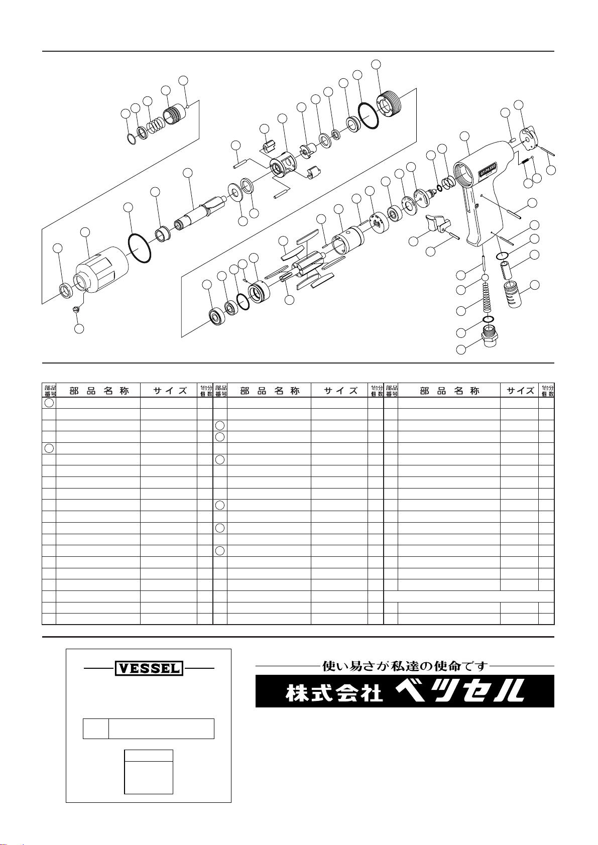
2. To lubricate the motor part, remove the air hose
from Air Inlet Bushing. Then apply appropriate
amount of lubrication oil for rotating mechanism
(VG-10, Clear) into Air Inlet and conduct several
seconds’ idling.
3. To lubricate the impact-driving parts, remove
Lubricant Port Screw and apply one to two drops
of lubrication oil to impact mechanism (VG-32,
Light Green) once every week.
To replace spent lubricant, remove Lubricant Port
Screw and dispose of the old lubricant. Then refill
the hammer housing with 7cc volume of new
lubrication oil for impact driving mechanism (VG-
32, Light Green). Excessive lubrication lowers the
working torque.
■AIR SUPPLY
1. Air tools can be adversely affected by moisture.
As air supplied from the compressor contains a lot
of moisture and dust, it is advisable to install a
filtering equipment and a lubricator in the pipeline
to remove such undesirable elements. Also,
accumulated water within the air tank needs to be
drained every day.
2. Before using a new air hose or air pipe, connect it
to the air compressor first to run a flow into it so
that the inside of it will be cleaned.
3. Keep the inside of air hoses and air pipes clean.
With dust and water accumulated within an air
hose or pipe,
the inner diameter of them becomes smaller and it
causes a drop in the working air pressure. It can also
cause the air tools to break down if such objects get
into them.
4. If the air hose is detached from the tool, keep the end
of the hose from falling onto the floor as dust or other
objects may come into the air hose.
5. The input air pressure needs to be maintained within
the 0.55MPa to 0.60MPa range by installing a
regulator at the tool end. Excessive air pressure
shortens the lifetime of impact-driving parts and
insufficient air pressure lowers the working torque and
causes its performance to be impaired.
6. Please conduct “idling” for a few seconds after
lubrication, as the lubricant would be flushed out with
exhaust air.
7. VESSEL Quick-Change Couplings are recommended
for more convenience.
■OPERATION
1. Do not tamper with the rotational parts as they are
adjusted with high precision. In case of malfunction,
please contact us for customer service.
2. Switch Reverse Lever to L (for counter-clockwise
revolution) or R (for clockwise revolution) to change
the rotational direction.
3. Set the tool tip on
to the screw and press Throttle Lever
to start.
4. Release Throttle Lever to stop the revolution after
completing the fastening job. Unnecessary driving will
damage both the screw / bolt and the impact-driving
mechanism.
5. Except for the after-lubrication flush (in reference to
the 6th note of AIR SUPPLY), avoid idling the unit with
no load.
Air Inlet
Bushing
Silencer
(360°free turn)
Throttle trigger
Anvil Hammer housing Motor housing Reverse lever
Bit sleeve
Lubricant
port screw