ASG, Division of Jergens, Inc.
15
7
0
0
S. Waterloo Road | Cleveland, OH 44110-3898 | Phone: (888) 486-6163 | Fax: (216) 481-4519 | Email: [email protected] | Web: www.asg-jergens.comdetermine whether the tool will operate correctly and perform
as designed.
18. The tool should be grounded while in use to protect the operator
from electric shock.
19. It only takes a slight amount of pressure for a push-to-start tool
to go into operaon.
Cauons in Operaon
1. If there are any problems, do not disassemble the tool. Stop
operaons and contact ASG immediately.
2. Never lubricate the tool with aerosol oil or similar lubricants.
3. Do not drop, hit, or abuse the tool.
4. Never use chemicals to wipe the body cover
5. Use only the correct voltage.
6. Do not pull the AC cord when unplugging from the power
outlet. Grasp the plug.
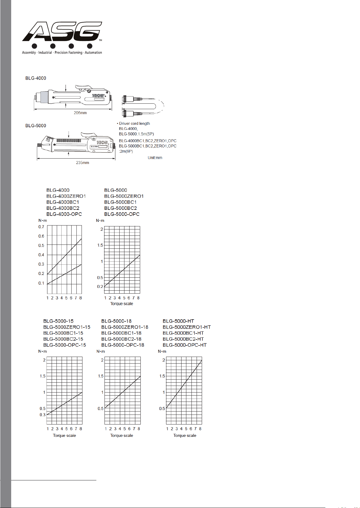
7. For safety use, do not set the torque adjusng nut higher than 10
on the torque adjusng scale
8. Use the tool intermiently: (Example: 0.5 seconds ON, 4.5
seconds OFF)
9. Do not ghten more than 720 tapping screws in an hour.
10. This tool is not for ghtening wood screws
11. Set the power switch to OFF before pung the tool in reverse.
12. If the tool is not being used, turn the tool o and unplug the AC
cord plug.
13. In push-to-start mode the driver automacally goes on when
pressure is applied to the bit end.
14. In push-to-start mode do not raise the driver from the screw
head unl rotaon has stopped.
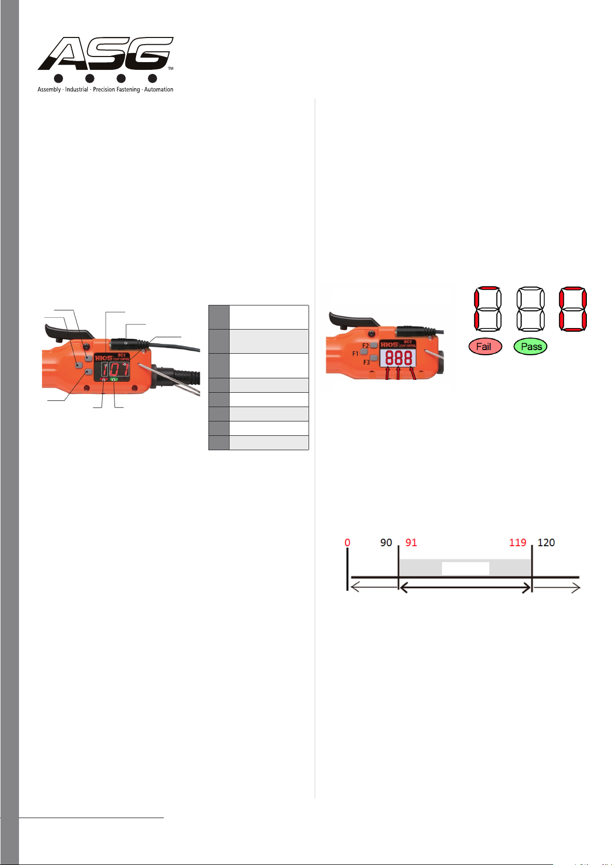
15. When a tool with an internal counter is used in combinaon
with an external counter, the external counter supercedes the
internal counter of the tool. Turn o the screwdriver’s counng
funcon before use.
16. When the output seng for Power HI/LOW is changed, the
screwdriver speed changes. In such cases, pay aenon to the
counter mer set value and reverse counter mer set value.
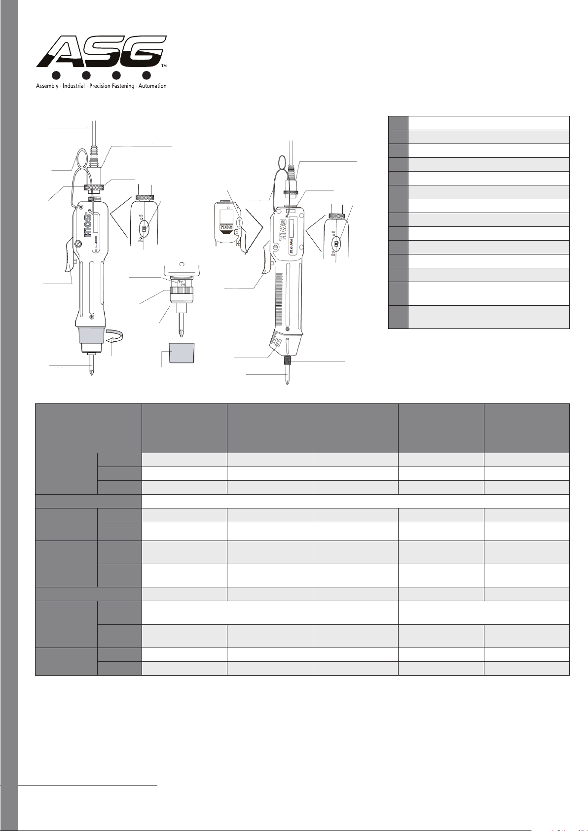
HIOS BLG Series: BLG-BC2
Operaonal Manual
BLG-4000, BLG-5000, BLG-BC1 (With Built in Screw Counter),
BLG-BC2/ZERO1 (With Built in Screw Counter and Pulse System),
BLG-OPC (For Use with Screw Counter)
Important: Please read and save the operang instrucons.
Warning: When using electric tools, the following basic safety
precauons should always be adhered to in order to reduce the
risk of re, electric shock, or personal injury.
Precauons
1. Keep Work Area Clean: Cluered areas and benches can result
in injuries.
2. Consider Work Area Environment: Do not expose tools to rain.
Do not use tools in damp or wet locaons. Keep work area
well lit. Never use the tool in an area with dangerous objects
present. (gasoline, benzene, thinner, gas glue, metallic objects,
etc.)
3. Secure Work: Use clamps or a vice to hold work piece.
4. Guard Against Electric Shock: Prevent body contact with
grounded surfaces.
5. Keep Away From Children and Unauthorized Personnel: Do not
allow children or unauthorized personnel to use the tool.
6. Store Idle Tools: When not in use, tools should be stored in a dry
and high or locked-up place.
7. Remove Adjusng Keys And Wrenches: Make a habit of
checking to see that keys and adjusng wrenches are removed
from the tool before turning it on.
8. Use The Correct Tool: Use the tool for the correct work for its
rated power and design.
9. Dress Properly: Do not wear loose clothing or jewelry as they
can be caught in moving parts. Wear protecve head wear to
contain long hair.
10. Use Safety Glasses: Also use a face or dust mask if the operaon
involves dust.
11. Do Not Abuse The Cord: Never carry the tool by its cord or pull
it to disconnect from the power outlet. Keep the cord away
from heat, oil, and sharp edges.
12. Do Not Overreach: Maintain proper foong and balance at all
mes.
13. Maintain Tools With Care: Keep tools clean for beer and
safer performance. Follow instrucons for lubricang and
changing accessories. To use the tool for an extended period
of me safely, perform periodical inspecons on the tool and if
damaged, contact ASG. Keep hands dry, clean, and free from oil
and grease. Inspect extension cords periodically and replace if
damaged.
14. Disconnect Tools: When the tool is not in use, such as aaching
and removing the bit, inspecon or cleaning, disconnect the tool
from the power outlet.
15. Avoid Unintenonal Starng: Ensure that the switch is o when
plugging in. Do not carry the tool with nger on the switch.
16. Stay Alert: Always remain vigilant, use common sense, and do
not operate the tool when you are red.
17. Check Damaged Parts: Before using the tool, a damaged
protecve cover or other parts should be carefully checked to