U-Scrape™
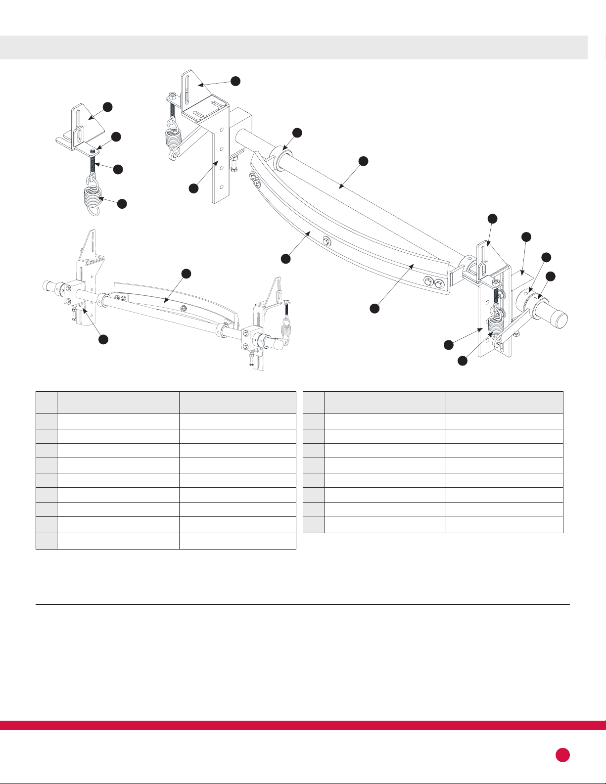
USCRAPE™ INSTALLATION
MAINTENANCE
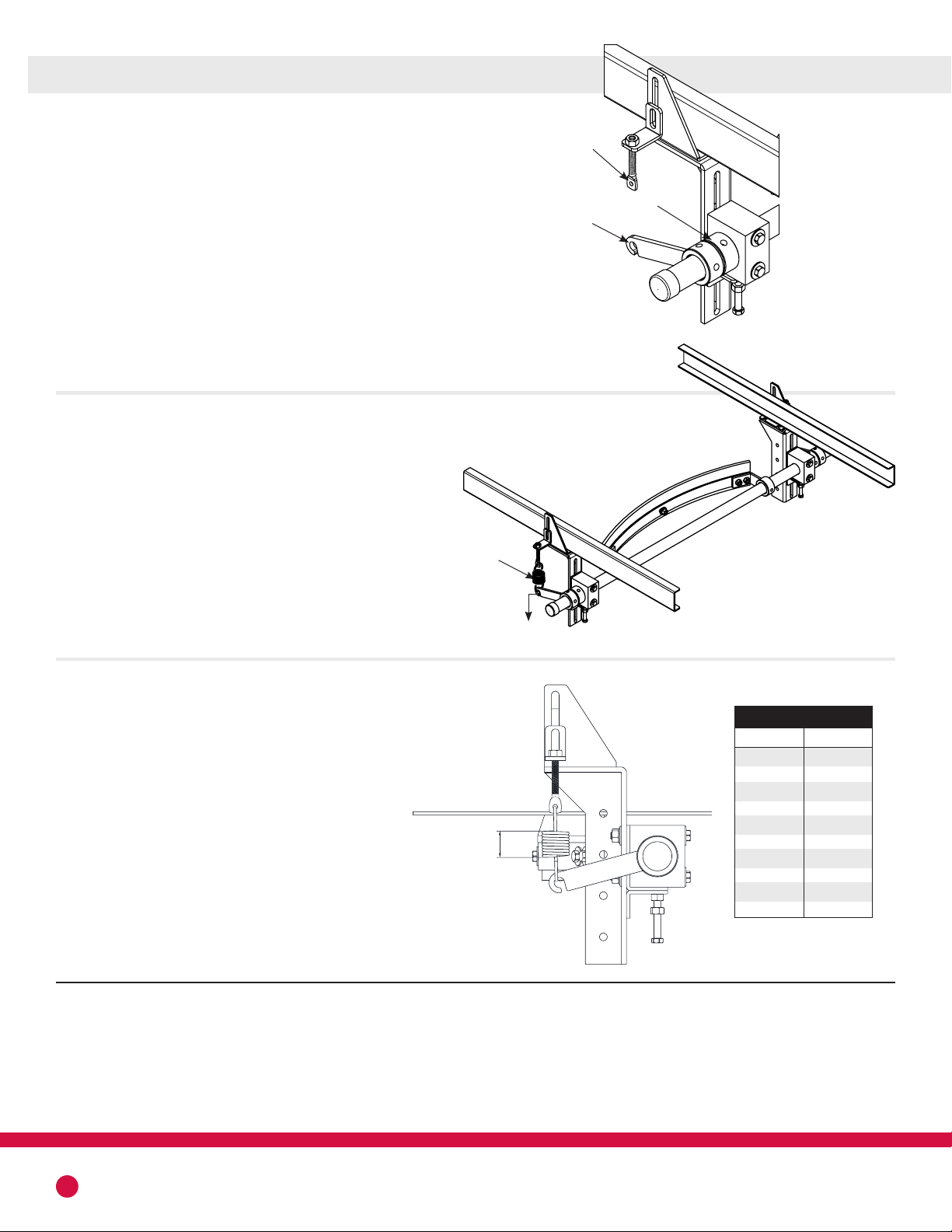
RETENSIONING OF USCRAPE™ CLEANER
TROUBLE SHOOTING
After one day of operation
• Inspect the cleaner for proper belt cleaning and operation.
Weekly operation
• Frequent inspection is the key to proper belt cleaning and easy Scraper servicing. Weekly
inspections are recommended, but actual service frequency may vary widely depending on
various plant operating conditions.
• Wash the entire cleaner regularly to prevent excessive buildup. If material tends to accumulate
on the Scraper Assembly then possible scraper relocation may be in order.
• Carefully inspect the wear tip of the cleaner blade. Make sure blade is not chipped or worn out.
(Replace when necessary)
• Inspect the belt surfaces and edges for cracks, splits, tears, holes or any other worn or damaged
condition occurring on the surfaces or edges of the belt itself. If necessary make repairs to the belt.
• Upon wear, it will be necessary to tightened the spring up using the nuts on the machine screw.
• When running out of thread on the machine screw, you will need to adjust the cleaner upward
using the bolt for the adjusting angle. Loosen the tube bushing bolts first to do this.
• There is even more upward adjust using the hanger extension bracket, or downward movement
of the power arms.
SolutionProblem
Excess vibration of the scraper.
Excess carryback.
Excess belt movement, cupping.
Unable to tension scraper properly,
belt moves away from blades.
Frozen material on scraper.
Make certain all bolts are tight. Move the center line of the tube closer to the belt
Install a hold down roller to stabilizer the belt surface.
Check for proper Scraper tension. Put additional tension on cleaner.
Check for wear on the cleaning tip.
Check thickness of carryback. If the cleaner must remove more than about 1/8” of material then an
additional cleaner may be needed
Install a hold down roller to reduce sag of the belt when tensioning.
Place heaters near scraper to melt frozen material. Or shut off the belt lock it out, test that the belt
does not turn on, and chip debris off. CAREFULLY . Use caution not to burn belt or cleaner.
5