www.asgco.com |800.344.4000
BC2™ INSTALLATION
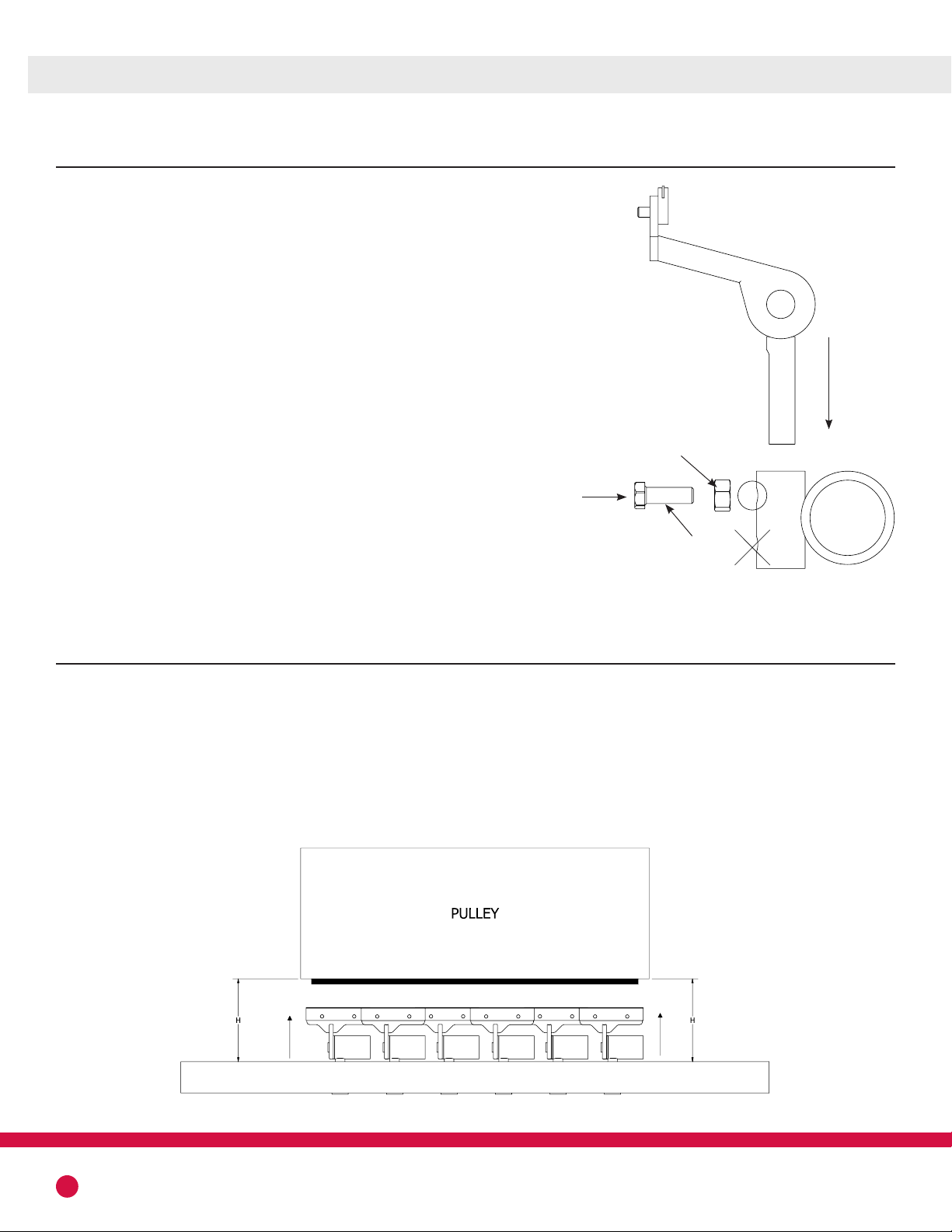
Jam Nut
Set Screw
OPERATION
With all modules inserted, bring the mounting tube up towards the belt ensuring the tube remains paral-
lel to the belt line and pulley. It is recommended to have both the tips”bottomed” out in the slots as
well as the modules inserted completely into the mounting tube.
Raise the tube until the back arms touch the belt. If the front arms touch first, adjust the rake angle and
ensure the arms are fully inserted into the mounting tube.
4
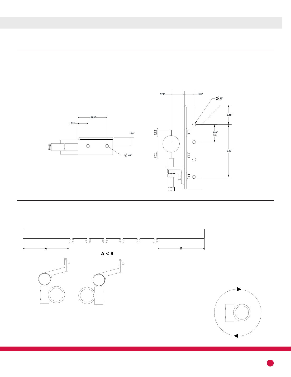
5. ARM TO TUBE INSTALLATION
With mounting brackets bolted or welded in place, insert the
tube through the chute cut outs.
Arms should be inserted into the mounting tube, alternating
short and long arms. On belt widths that have odd numbers of
arm modules, more short arms will be included than long arms.
Starting with a short arm will ensure correct arm arrangement.
A set screw and jam nut are provided to fasten the arm modules
to the tube. Regardless of mounting orientation, the set screw
will be inserted in the “Top” hole of the mounting tube. Hand
tighten the set screw so that the modules will not move around
will adjusting the mounting tube height.
If belt profile is “cupped”, tip angle may be adjusted individually
for better belt contact. Fine adjustment may be necessary to
avoid any gaps between the tips and the belt. This adjustment
will need to be done at the installed location, which may be
within a chute or under a conveyor system.