Ashdown CTM-200-RACK User manual

USER MANUAL
ENGLISH / FRANÇAIS / DEUTSCH / ESPAÑOL

ASHDOWN ENGINEERING - CTM-200-RACK USER GUIDE
INTRODUCTION
Built to be gigged the CTM-200R rack head is housed in a 2mm mild steel chassis with spot
welded supports fabricated in Essex, England, hand nished and powder coated in black before
being tted with its beautifully engineered heavy duty circuit boards which support the valve
compliment of four KT-88 power tubes as well as the array of pre amp valves consisting of 2 x
ECC-832 2 x ECC-82 1 x ECC-99.
Thank you for purchasing your Ashdown Engineering Amplier and welcome to
the family! We really think you’ve made the right choice and know that this
amplier will give you years of great tone and service.
It is a machine though and needs to be looked after, please read
through this user manual which will help you get the most out of
your new Amp and keep it running as long as some of our
happiest and very famous customers.
Please register this product online so we can make sure we give you years of
customer support through our friendly in-house service centre.
Here is where you need to visit to register your product:
http://www.ashdownmusic.com/pages/register-your-product
THANK YOU
REGISTER ONLINE VU

ASHDOWN ENGINEERING - CTM-200-RACK USER GUIDE USER GUIDE
CTM-200-RACK
FRONT PANEL FACILITIES
INPUTS - There are two instrument inputs marked LOW and HIGH. The LOW input
is highly sensitivity and also high impedance to suit the output from PASSIVE (Low
Output) basses - The HIGH input is low sensitivity and lower impedance to suit the
output from ACTIVE (High Output) basses. Plugging an active (High Output) bass
into the LOW input will overload the input, creating a fatter, warmer and more
distorted sound. Experiment by plugging your bass into either input to achieve the
desired sound.
EFFECTS SEND AND RETURN - These 1/4” jack sockets should be used to connect
to an external effects device or pedal board. The EFFECTS SEND output should
connect to the INPUT of the effects unit, and the output of the effects unit should be
connected to the EFFECTS RETURN input.
EQ CONTROLS - Use the MIDDLE, BASS and TREBLE controls to effect the overall
tone of the sound. The MID SHIFT switch causes the MIDDLE control to operate on
higher frequencies in the up position, and lower frequencies in the down position.
The BASS SHIFT switch causes the BASS control to operate on deeper frequencies
in the up position, and less deep frequencies in the down position. The BRIGHT
switch adds an overall brightness to the sound when in the up position. (Note: The
BRIGHT switch is not effective when the GAIN control is set to full).
GAIN - This controls the level of the signal sent to the MASTER section. To achieve a
cleaner sound, turn the GAIN control down and the MASTER up. To achieve a richer,
more distorted sound, turn the GAIN control up and the MASTER down.
MASTER - This controls the overall output of the amplier.
MUTE - In the up position, this switch mutes the out put of the amplier (useful for
tuning, etc.).
PRE/POST - This switch determines whether the signal from the DI OUTPUT (see
Rear Panel Facilities) is taken before/PRE the EQ section (down position) or after/
POST (up position).
VU METER - The VU meter provides a visual indication of the output level of the
amplier. It also acts as a bias meter, please see the following page for more details.
REAR PANEL FACILITIES
DI OUTPUT - This 1/4” stereo jack socket is used to connect the amplier to a low
impedance, balanced input on a PA system or recording mixer. The signal can be
taken PRE or POST EQ (see above), ie with or without the tone shaping added by
the EQ section of the amplier.
LINE INPUT - This 1/4” jack socket is used to connect the output of line level devices
such as samplers and sound modules.
SPEAKER OUTPUTS - There are dedicated Speakon connectors for 2, 4 and 8! load
speaker cabinet congurations. It is important that the correct output or outputs are
used to match the impedance load of your cabinets. Please refer to the diagrams
later in this manual.
OFF/PREHEAT - Use this switch to pre-heat the valves, bringing them up to the
correct operating temperature before performing.
STANDBY/FULL - No signal is sent to the speakers when this switch is in the
STANDBY position. Switch to FULL when you are ready to perform.

ASHDOWN ENGINEERING - CTM-200-RACK USER GUIDE USER GUIDE
CTM-200-RACK
THE VU METER
The VU meter tted to the CTM is a dual function meter detailed as follows:
By using the push button selector switch marked “AUDIO / BIAS” the functions are
accessed in the following manner:
1/ “AUDIO” - In audio mode the meter is set to read the audio output of each of the
six power tubes and each can be measured by utilising the rotary selector switch
on the front panel. Whilst playing this is the normal mode of operation of the meter
and the reading obtained will be a direct indication of the power being produced
by each output tube, the meter is calibrated so that when the needle reaches the
start of the red section the power tube being measured will be producing maximum
clean volume.
The switch can be rotated to select any of the power tubes and its relative output
will be indicated on the meter, note that when performing this test you will need to
play at equal volume for each test.
2/ “BIAS” - In this mode the meter will glow RED.
To check the bias of the output tubes proceed as follows:
Run the amplier for at least 10 mins to allow the output tubes to fully heat up with
the amplier set to mute. Standby on. Select.. Tube 1 and with an insulated jewelers
screwdriver gently adjust the trimmer situated on the rear panel. The reading to aim
for is the needle just at the start of the red ie 0db.
Note that although each tube can be adjusted individually it is possible to get tubes
that cannot be adjusted to the correct reading, these can still be used providing the
reading is not in the red, a lower reading is acceptable and will note impact audibly
on the power output or sound quality of the amplier.
Please also note that the trimmers are 25 turn types to make adjustment easy, This
type of adjuster has no end stop so if you reach a point where the adjuster will
not give any more adjustment then the output tube will have to be replaced if the
reading is to high ie in the RED.
Repeat this for each of the four output tubes in turn.
RETURN THE METER TO “audio” MODE AFTER BIASING. DO NOT RUN THE
AMPLIFIER IN BIAS MODE WHILST PLAYING.
Note there is a protection fuse tted to each of the output tubes and if no reading
is obtained on the meter this fuse will have failed. The protection fuses are situated
next to the output they are protecting the correct rating is 315Ma quick blow, in the
event of a blown fuse they MUST be replaced with fuses of the correct rating and
type.
A continually blowing fuse would indicate either an incorrectly biased output tube
or a defective output tube.

ASHDOWN ENGINEERING - CTM-200-RACK USER GUIDE USER GUIDE
CTM-200-RACK
VALVE COMPLIMENT:
POWER:
PRE:
KT-88 KT-88 KT-88 KT-88
ECC-832 ECC-82ECC-832 ECC-82
SPECIFICATIONS:
Inputs
High Input Impedance - 3.9M ohms Input range 150mv to 20v p - p
Low Input Impedance - 10k ohms Input range 300mv to 40v p - p
Effects Return Impedance - 22k ohms Input level 0dbu nominal
Line Input Impedance - 22k ohms Input range 300mV
Outputs
Effects Send Impedance - 22k ohms Level 0dbu nominal
D.I.Output 420 ohms balanced pre ground lift Level -20dbu nominal
Speaker Outputs Minimum Impedance - 4 ohms
Frequency Response -3db at 22hz and 25khz
Headphone Output 3.5mm Jack output @ 320hms
Equalisation
Bass +/- 15db @ 100hz
Middle +/- 15db @ 660hz
Treble +/- 15db @ 7khz shelving
Shape + 8db @ 50hz + 10db @ 10khz
Signal to Noise Better than 80db (E.Q. Flat)
Distortion Less than 0.5% Thd
Output Power 200watts into 4 ohms

ASHDOWN ENGINEERING - CTM-200-RACK GUIDE DE L’UTILISATEUR
INTRODUCTION
Construit pour être gigged la tête de rack CTM-200R est logé dans un châssis en acier doux
de 2mm avec des supports soudés spot fabriqués dans l’Essex, Angleterre, ni à la main et en
poudre enduit de noir avant d’être équipé de ses circuits imprimés robustes magniquement
conçus qui soutiennent le compliment valve de quatre tubes de puissance KT-88 ainsi que la
gamme de valves pré-ampli composé de 2 x ECC-832 2 x ECC-82 1 x ECC-99.
VU
Merci d’avoir acheté votre amplicateur d’ingénierie Ashdown et bienvenue
dans la famille! Nous pensons vraiment que vous avez fait le bon choix et sa-
vons que cette amplicateur vous donnera des années de grande tonalité et
de service. C’est une machine si et doit être pris en charge, s’il vous plaît lire
à travers ce manuel d’utilisation qui vous aidera à tirer le meilleur parti de
votre nouvel ampli et le garder en cours d’exécution aussi longtemps que
certains de nos clients les plus heureux et très célèbres.
S’il vous plaît enregistrer ce produit en ligne an que nous puissions nous
assurer que nous vous donnons des années de soutien à la clientèle par
l’intermédiaire de notre centre de service interne convivial.
Voici où vous devez visiter pour enregistrer votre produit :
http://www.ashdownmusic.com/pages/register-your-product
MERCI
INSCRIVEZ-VOUS EN LIGNE

ASHDOWN ENGINEERING - CTM-200-RACK GUIDE DE L’UTILISATEUR GUIDE DE L’UTILISATEUR
CTM-200-RACK
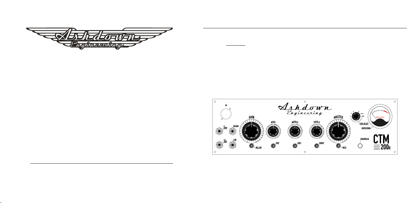
INSTALLATIONS DU PANNEAU AVANT
ENTRÉES - Il y a deux entrées d’instrument marquées LOW et HIGH. L’entrée LOW est
très sensible et aussi une grande impedance pour convenir à la SORTIE DES basses
PASSIVE (Low Output) - L’entrée HIGH est faible sensibilité et une plus faible impedance
pour convenir à la sortie des basses ACTIVE (High Output). Brancher une basse active
(high output) dans l’entrée LOW surchargera l’entrée, créant un son plus gras, plus chaud
et plus déformé. Expérimentez en branchant votre basse dans l’une ou l’autre entrée
pour obtenir le son désiré.
EFFETS ENVOYER ET REVENIR - Ces prises jack de 1/4 » doivent être utilisées pour se
connecter à un dispositif d’effets externes ou à un pedal board. La sortie EFFECTS SEND
doit se connecter à l’entrée de l’unité d’effets, et la sortie de l’unité d’effets doit être
connectée à l’entrée EFFETS RETURN.
CONTRÔLES EQ - Utilisez les commandes MIDDLE, BASS et TREBLE pour effectuer
le ton global du son. Le commutateur MID SHIFT fait fonctionner le contrôle MIDDLE
sur des fréquences plus élevées en position verticale et des fréquences inférieures en
position descendante. Le commutateur BASS SHIFT fait fonctionner le contrôle BASS sur
des fréquences plus profondes en position verticale, et des fréquences moins profondes
en position descendante. Le commutateur BRIGHT ajoute une luminosité globale au son
lorsqu’il est en position verticale. (Remarque : Le commutateur BRIGHT n’est pas efcace
lorsque le contrôle GAIN est réglé à plein).
GAGNER - Cela contrôle le niveau du signal envoyé à la section MASTER. Pour obtenir un
son plus propre, baissez le contrôle GAIN et le MASTER vers le haut. Pour obtenir un son
plus riche et plus déformé, activez le contrôle GAIN et le MASTER vers le bas.
MAÎTRE - Cela contrôle la sortie globale de l’amplicateur.
MUET - En position verticale, ce switch coupe le put out de l’amplicateur (utile pour le
réglage, etc.).
PRÉ/ PUBLIER - Ce commutateur détermine si le signal du DI OUTPUT (voir Installations
de panneau arrière) est pris avant/PRE la section EQ (position descendante) ou après/
POST (position vers le haut).
VU MÈTRES - Le compteur VU fournit une indication visuelle du niveau de sortie de
l’amplicateur. Il agit également comme un compteur de biais, s’il vous plaît voir la page
suivante pour plus de détails.
INSTALLATIONS DE PANNEAU ARRIÈRE
SORTIE DI - Cette prise de prise stéréo jack de 1/4 » est utilisée pour connecter
l’amplicateur à une faible impedance, entrée équilibrée sur un système de sonorisation
ou un mélangeur d’enregistrement. Le signal peut être pris PRE ou POST EQ (voir ci-
dessus), c’est à dire avec ou sans la mise en forme de tonalité ajoutée par la section EQ
de l’amplicateur.
ENTRÉE DE LIGNE - Cette prise jack de 1/4 » est utilisée pour connecter la sortie des
périphériques de niveau ligne tels que les échantillonneurs et les modules sonores.
SORTIES HAUT-PARLEURS - Il existe des connecteurs Speakon dédiés pour les
congurations de haut-parleurs de charge 2, 4 et 8!. Il est important que la sortie ou les
sorties correctes soient utilisées pour correspondre à la charge d’impédance de vos
armoires. Veuillez consulter les diagrammes plus loin dans ce manuel.
DE/PRÉCHAUFFER - Utilisez ce commutateur pour préchauffer les vannes, les amenant
à la température de fonctionnement correcte avant d’effectuer.
VEILLE/PLEIN - Aucun signal n’est envoyé aux haut-parleurs lorsque ce commutateur
est en position STANDBY. Passez à FULL lorsque vous êtes prêt à effectuer.

LE COMPTEUR VU
Le compteur VU monté sur le CTM est un compteur à double fonction détaillé comme
suit : En utilisant le commutateur sélecteur de bouton poussoir marqué « AUDIO / BIAS »
les fonctions sont accessibles de la manière suivante:
1/ “AUDIO” - En mode audio, le compteur est réglé pour lire la sortie audio de
chacun des six tubes électriques et chacun peut être mesuré en utilisant l’interrupteur
du sélecteur rotatif sur le panneau avant. Tout en jouant c’est le mode normal de
fonctionnement du compteur et la lecture obtenue sera une indication directe de la
puissance produite par chaque tube de sortie, le compteur est calibré de sorte que
lorsque l’aiguille atteint le début de la section rouge le tube de puissance mesuré
produira un volume maximum propre.
Le commutateur peut être tourné pour sélectionner l’un des tubes de puissance et sa
sortie relative sera indiquée sur le compteur, notez que lors de l’exécution de ce test,
vous devrez jouer à volume égal pour chaque test.
2/ “BIAS” - Dans ce mode, le compteur brillera ROUGE.
Pour vérier le biais des tubes de sortie procéder comme suit:
Faire fonctionner l’amplicateur pendant au moins 10 minutes pour permettre aux tubes
de sortie de chauffer complètement avec l’amplicateur réglé pour couper le son. Tenez-
vous en attente. choisir.. Tube 1 et avec un tournevis jewelers isolé ajustez doucement la
tondeuse située sur le panneau arrière. La lecture à viser est l’aiguille juste au début de
la rouge c’est à dire 0db.
Notez que bien que chaque tube peut être ajusté individuellement, il est possible
d’obtenir des tubes qui ne peuvent pas être ajustés à la bonne lecture, ceux-ci peuvent
toujours être utilisés à condition que la lecture n’est pas dans le rouge, une lecture
inférieure est acceptable et notera l’impact audible sur la puissance de sortie ou la
qualité sonore de l’amplicateur.
S’il vous plaît également noter que les tondeuses sont 25 types de tour pour rendre
l’ajustement facile, Ce type d’ajusteur n’a pas d’arrêt nal, donc si vous atteignez un
point où l’ajusteur ne donnera pas plus d’ajustement, puis le tube de sortie devra être
remplacé si la lecture est à haute c’est à dire dans le RED.
Répétez cette répétition pour chacun des quatre tubes de sortie à son tour.
REMETTRE LE COMPTEUR EN MODE “audio” APRÈS AVOIR BIAISÉ. N’EXÉCUTEZ PAS
L’AMPLIFICATEUR EN MODE BIAIS PENDANT LA LECTURE.
Notez qu’il y a un fusible de protection monté sur chacun des tubes de sortie et si
aucune lecture n’est obtenue sur le compteur, ce fusible aura échoué. Les fusibles de
protection sont situés à côté de la sortie qu’ils protègent la bonne note est 315Ma coup
rapide, en cas de fusible soufé, ils doivent être remplacés par des fusibles de la bonne
note et le type.
Un fusible soufant continuellement indiquerait soit un tube de sortie mal biaisé, soit un
tube de sortie défectueux.
ASHDOWN ENGINEERING - CTM-200-RACK GUIDE DE L’UTILISATEUR GUIDE DE L’UTILISATEUR
CTM-200-RACK

SPÉCIFICATIONS:
Entrées
Entrée élevée Impédance - 3.9M ohms Plage d’entrée 150mv to 20v p - p
Faible entrée Impédance - 10k ohms Plage d’entrée 300mv to 40v p - p
Retour des effets Impédance - 22k ohms Niveau d’entrée 0dbu nominal
Entrée en ligne Impédance - 22k ohms Plage d’entrée 300mV
Sorties
Effets envoyer Impédance - 22k ohms Niveau 0dbu nominal
D.I. Sortie 420 ohms équilibré Nxiveau de levage avant le sol
-20dbu nominal
Sorties de haut-parleurs
Minimum Impédance - 4 ohms
Réponse de fréquence -3db at 22hz and 25khz
Sortie casque 3.5mm Jack output @ 320hms
Égalisation
Basse +/- 15db @ 100hz
Milieu +/- 15db @ 660hz
Triple +/- 15db @ 7khz shelving
Forme + 8db @ 50hz + 10db @ 10khz
Signal au bruit Mieux que 80db (E.Q. Plat)
Distorsion moins de 0.5% Thd
Puissance de sortie 200watts dans 4 ohms
KT-88 KT-88 KT-88 KT-88
ECC-832 ECC-82ECC-832 ECC-82
SOUPAPE COMPLIMENT:
POUVOIR:
PRÉ:
ASHDOWN ENGINEERING - CTM-200-RACK GUIDE DE L’UTILISATEUR GUIDE DE L’UTILISATEUR
CTM-200-RACK

ASHDOWN ENGINEERING - CTM-200-RACK BEDIENUNGSANLEITUNG
EINLEITUNG
Gebaut, um gebemannt zu werden, ist der CTM-200R Rackkopf in einem 2mm milden Stahlge-
häuse mit punktgeschweißten Stützen in Essex, England, handfertig und pulverbeschichtet in
schwarz, untergebracht, bevor er mit seinen wunderschön konstruierten Hochleistungs-Leiter-
platten ausgestattet wird, die das Ventilkompliment von vier KT-88-Leistungsrohren sowie die
Anordnung von Vorverstärkerventilen aus 2 x ECC-832 2 x ECC-82 1 x ECC-99 unterstützen.
VU
Vielen Dank für den Kauf Ihres Ashdown Engineering Verstärkers und herzlich
willkommen in der Familie! Wir glauben wirklich, dass Sie die richtige Wahl
getroffen haben und wissen, dass dies Verstärker wird Ihnen Jahre von
großem Ton und Service geben. Es ist eine Maschine obwohl und muss
gepegt werden, lesen Sie bitte durch diese Bedienungsanleitung, die Ihnen
hilft, das Beste aus Ihren neuen Amp und halten Sie ihn am Laufen, solange
einige unserer glücklichste und sehr berühmte Kunden.
Bitte registrieren Sie dieses Produkt online, damit wir Ihnen über unser
freundliches in-house Service Center jahrelangen Kundensupport bieten.
Hier müssen Sie Ihr Produkt registrieren:
http://www.ashdownmusic.com/pages/register-your-product
VIELEN DANK
REGISTRARSE EN LÍNEA

ASHDOWN ENGINEERING - CTM-200-RACK CTM-200-RACK
FRONTPANEL-EINRICHTUNGEN
INPUTS - Es gibt zwei Instrumenteneingänge mit der Aufschrift LOW und HIGH. Der
LOW-Eingang ist hochempndlich und auch hoch impedanz. Das Einstecken eines
aktiven (High Output) Basses in den LOW-Eingang überlastet den Eingang und erzeugt
einen dickeren, wärmeren und verzerrteren Klang. Experimentieren Sie, indem Sie Ihren
Bass in einen der beiden Eingänge stecken, um den gewünschten Sound zu erzielen.
EFFEKTE SEND UND RETURN - Diese 1/4” Buchsen sollten verwendet werden, um an
ein externes Effektgerät oder Pedalboard anzuschließen. Die EFFECTS SEND-Ausgabe
sollte eine Verbindung mit dem INPUT der Effekteinheit herstellen, und die Ausgabe der
Effekteinheit sollte mit dem EFFECTS RETURN-Eingang verbunden werden.
EQ STEUERELEMENTE - Verwenden Sie die Steuerelemente MIDDLE, BASS und TREBLE,
um den Gesamtton des Sounds zu bewirken. Der MID SHIFT-Schalter bewirkt, dass
die MIDDLE-Steuerung auf höheren Frequenzen in der Auf-Position und niedrigeren
Frequenzen in der Abwärtsposition arbeitet. Der BASS SHIFT Schalter bewirkt, dass
die BASS-Steuerung auf tieferen Frequenzen in der Up-Position und weniger tiefen
Frequenzen in der Abwärtsposition arbeitet. Der BRIGHT-Schalter fügt dem Ton in der
Up-Position eine Gesamthelligkeit hinzu. (Hinweis: Der BRIGHT-Schalter ist nicht wirksam,
wenn das GAIN-Steuerelement auf “Voll” eingestellt ist).
GEWINNEN - Steuert den Pegel des Signals, das an den MASTER-Abschnitt gesendet
wird. Um einen saubereren Klang zu erzielen, schalten Sie die GAIN-Steuerung nach
unten und die MASTER-Steuerung nach oben. Um einen reicheren, verzerrteren Klang zu
erzielen, drehen Sie die GAIN-Steuerung nach oben und die MASTER nach unten.
MASTER - Steuert den Gesamtausgang des Verstärkers.
STUMM - In der Up-Position schaltet dieser Schalter den Aussatz des Verstärkers stumm
(nützlich für die Abstimmung, etc.).
PRE/BEREITSTELLEN - Dieser Schalter bestimmt, ob das Signal vom DI OUTPUT (siehe
Rückraumeinrichtungen) vor/PRE des EQ-Abschnitts (Abwärtsposition) oder nach dem
Post (Up-Position) aufgenommen wird.
VU METER - Das VU-Messgerät liefert eine visuelle Anzeige des Ausgangspegels des
Verstärkers. Es fungiert auch als Bias Meter, siehe die folgende Seite für weitere Details.
AUSSTATTUNG DER RÜCKWAND
DI AUSGABE - Diese 1/4” Stereo-Klinkenbuchse wird verwendet, um den Verstärker
an eine niedrige Impedanz, symmetrischen Eingang an einem PA-System oder
Aufnahmemischer anzuschließen. Das Signal kann PRE oder POST EQ (siehe oben)
genommen werden, d.h. mit oder ohne die Tonformung, die durch den EQ-Bereich des
Verstärkers hinzugefügt wird.
LINIE EINGABE - Diese 1/4” Klinkenbuchse wird verwendet, um den Ausgang von Line-
Level-Geräten wie Samplern und Soundmodulen zu verbinden.
LAUTSPRECHER AUSGÄNGE - Es gibt spezielle Speakon-Steckverbinder für 2, 4 und 8!
Ladelautsprecher-Schrankkongurationen. Es ist wichtig, dass die richtigen Ausgänge
oder Ausgänge verwendet werden, um die Impedanzlast Ihrer Schränke abzugleichen.
Bitte beachten Sie die Diagramme weiter unten in diesem Handbuch.
AUSGÄNGE/VORHEIZEN - Verwenden Sie diesen Schalter, um die Ventile vorzuheizen
und sie vor der Ausführung auf die richtige Betriebstemperatur zu bringen.
STANDBY/VOLL - Es wird kein Signal an die Lautsprecher gesendet, wenn sich dieser
Schalter in der STANDBY-Position bendet. Wechseln Sie zu FULL, wenn Sie bereit sind,
die Ausführung durchzuführen.
BEDIENUNGSANLEITUNGBEDIENUNGSANLEITUNG

ASHDOWN ENGINEERING - CTM-200-RACK CTM-200-RACK
DER VU METER
Der an der CTM angebrachte VU-Meter ist ein Dual-Funktionsmesser, der wie folgt
detailliert ist:
Über den Tastenschalter mit der Aufschrift “AUDIO / BIAS” wird auf die Funktionen wie
folgt zugegriffen:
1/ “AUDIO” - Im Audio-Modus ist das Messgerät so eingestellt, dass der Audioausgang
jedes der sechs Leistungsröhren gelesen wird und jeder kann durch die Verwendung
des Drehwahlschalters auf der Frontplatte gemessen werden. Während das Spielen
die normale Betriebsart des Messgeräts ist und der erhaltene Messwert eine direkte
Anzeige der Von jedem Ausgangsrohr erzeugten Leistung ist, wird das Messgerät so
kalibriert, dass, wenn die Nadel den Start des roten Abschnitts erreicht, das zu messende
Leistungsrohr ein maximales sauberes Volumen erzeugt.
Der Schalter kann gedreht werden, um eines der Leistungsrohre auszuwählen und seine
relative Ausgabe wird auf dem Messgerät angezeigt, beachten Sie, dass Sie bei der
Durchführung dieses Tests für jeden Test mit gleicher Lautstärke spielen müssen.
2/ “BIAS” - In diesem Modus leuchtet das Messgerät ROT.
Um die Verzerrung der Ausgangsrohre zu überprüfen, gehen Sie wie folgt vor:
Führen Sie den Verstärker mindestens 10 Min. aus, damit sich die Ausgangsröhren
vollständig erwärmen können, wenn der Verstärker stummgeschaltet ist. Standby-
Einschalten. Auswählen.. Rohr 1 und mit einem isolierten Juwelier Schraubendreher
vorsichtig den Trimmer auf der Rückseite zu setzen. Die Zusendezeit ist die Nadel direkt
am Anfang des roten dh 0db.
Beachten Sie, dass, obwohl jedes Rohr individuell eingestellt werden kann, ist es möglich,
Röhren zu erhalten, die nicht auf den richtigen Messwert eingestellt werden können,
diese können immer noch verwendet werden, vorausgesetzt, der Messwert ist nicht in
rot, ein niedrigerer Messwert ist akzeptabel und wird die Auswirkungen hörbar auf die
Leistung oder die Klangqualität des Verstärkers bemerken.
Bitte beachten Sie auch, dass die Trimmer sind 25 Turn-Typen, um die Einstellung einfach
zu machen, Diese Art von Einsteller hat keinen Endanschlag, so dass, wenn Sie einen
Punkt erreichen, wo der Einsteller keine weitere Einstellung geben wird, dann muss das
Ausgangsrohr ersetzt werden, wenn der Messwert zu hoch ist dh in der RED.
Wiederholen Sie dies für jedes der vier Ausgangsrohre nacheinander.
ZURÜCK ZUM ZÄHLER“audio” MODUS NACH VOREINGENOMMENHEIT. FÜHREN SIE
DEN VERSTÄRKER WÄHREND DER WIEDERGABE NICHT IM BIAS-MODUS AUS.
Beachten Sie, dass an jedem der Ausgangsrohre eine Schutzsicherung angebracht
ist, und wenn kein Messwert auf dem Messgerät erzielt wird, ist diese Sicherung
fehlgeschlagen. Die Schutzsicherungen benden sich neben dem Ausgang, den sie
schützen die richtige Bewertung ist 315Ma Schnellschlag, im Falle einer geblasenen
Sicherung MÜSSEN sie durch Sicherungen der richtigen Bewertung und Typ ersetzt
werden.
Eine ständig blasende Sicherung würde entweder auf ein falsch verzerrtes Ausgangsrohr
oder ein defektes Ausgangsrohr hinweisen.
BEDIENUNGSANLEITUNGBEDIENUNGSANLEITUNG

ASHDOWN ENGINEERING - CTM-200-RACK CTM-200-RACK
KT-88 KT-88 KT-88 KT-88
ECC-832 ECC-82ECC-832 ECC-82
VENTIL KOMPLIMENT:
MACHT:
PRE:
BEDIENUNGSANLEITUNGBEDIENUNGSANLEITUNG
SPEZIFIKATIONEN:
Eingänge
Hoch Eingabe Impedanz - 3.9M ohms Eingangsbereich 150mv to 20v p - p
Niedrig Eingabe Impedanz - 10k ohms Eingangsbereich 300mv to 40v p - p
Effekte-Rückkehr Impedanz - 22k ohms Eingangspegel 0dbu Nominale
Linie Eingabe Impedanz - 22k ohms Eingangsbereich 300mV
Ausgänge
Effekte senden Impedanz - 22k ohms Level 0dbu Nominale
D.I.Ausgabe 420 ohms Ausgewogene Vorbodenliftlevel -20dbu Nominale
Lautsprecherausgänge Minimale Impedanz - 4 ohms
Frequenzgang -3db at 22hz and 25khz
Kopfhörerausgang 3.5mm Jack Ausgabe @ 320hms
Ausgleich
Bass +/- 15db @ 100hz
Mitte +/- 15db @ 660hz
Höhen +/- 15db @ 7khz Regale
Form + 8db @ 50hz + 10db @ 10khz
Signal zum Rauschen Besser als 80db (E.Q. Flach)
Verzerrung Weniger als 0.5% Thd
Ausgangsleistung 200watts in 4 ohms

ASHDOWN ENGINEERING - CTM-200-RACK MANUAL DEL USUARIO
INTRODUCCIÓN
Construido para ser gigged el cabezal del bastidor CTM-200R se encuentra en un chasis de
acero suave de 2 mm con soportes soldados puntuales fabricados en Essex, Inglaterra, acabado
a mano y recubierto de polvo en negro antes de ser equipado con sus placas de circuito de
servicio pesado bellamente diseñadas que soportan el cumplido de válvula de cuatro tubos de
potencia KT-88, así como la matriz de válvulas preamplicadoras que constan de 2 x ECC-832 2
x ECC-82 1 x ECC-99.
VU
Gracias por comprar su amplicador de ingeniería Ashdown y bienvenido
a la familia! Realmente creemos que usted ha tomado la decisión correcta y
saber que este amplicador le dará años de gran tono y servicio.
Es una máquina, sin embargo, y necesita ser cuidado, por favor lea
a través de este manual de usuario que le ayudará a sacar el máximo partido
a su nuevo Amplicador y mantenerlo funcionando siempre y cuando
algunos de nuestros clientes más felices y muy famosos.
Por favor, registre este producto en línea para que podamos asegurarnos
de que le damos años de atención al cliente a través de nuestro amable
centro de servicio interno.
Aquí es donde necesita visitar para registrar su producto:
http://www.ashdownmusic.com/pages/register-your-product
GRACIAS
REGISTRARSE EN LÍNEA

ASHDOWN ENGINEERING - CTM-200-RACK CTM-200-RACK
INSTALACIONES DEL PANEL FRONTAL
ENTRADAS - Hay dos entradas de instrumento marcadas como LOW y HIGH. La
entrada LOW es altamente sensible y también alta impedancia para adaptarse a
la salida de graves PASIVOS (baja salida) - La entrada HIGH es baja sensibilidad
e impedancia inferior para adaptarse a la salida de graves ACTIVOS (Alta Salida).
Tapar un bajo activo (alta salida) en la entrada LOW sobrecargará la entrada,
creando un sonido más gordo, cálido y distorsionado. Experimente conectando su
bajo en cualquiera de las entradas para lograr el sonido deseado.
EFECTOS ENVIAR Y DEVOLVER - Estos zócalos jack de 1/4” deben utilizarse para
conectarse a un dispositivo de efectos externos o a una placa de pedal. La salida
EFFECTS SEND debe conectarse a la ENTRADA de la unidad de efectos y la salida
de la unidad de efectos debe conectarse a la entrada EFFECTS RETURN.
CONTROLES DE ECUALIZACIÓN - Utilice los controles MIDDLE, BASS y TREBLE
para realizar el tono general del sonido. El interruptor MID SHIFT hace que el
control MIDDLE funcione en frecuencias más altas en la posición superior y
frecuencias más bajas en la posición descendente. El switch BASS SHIFT hace que
el control BASS funcione en frecuencias más profundas en la posición de arriba, y
frecuencias menos profundas en la posición descendente. El interruptor BRIGHT
añade un brillo general al sonido cuando está en posición de arriba. (Nota: El
interruptor BRIGHT no es efectivo cuando el control GAIN está congurado en full).
GANAR - Esto controla el nivel de la señal enviada a la sección MASTER. Para lograr
un sonido más limpio, baje el control GAIN y el MASTER hacia arriba. Para lograr un
sonido más rico y distorsionado, sube el control GAIN y baja el MASTER.
MAESTRO - Esto controla la salida general del amplicador.
SILENCIO - En la posición hacia arriba, este interruptor silencia el apagado del
amplicador (útil para ajustar, etc.).
PRE/EXPONER - Este interruptor determina si la señal del DI OUTPUT (consulte
Las instalaciones del panel trasero) se toma antes/PRE la sección EQ (posición
descendente) o después/POST (posición hacia arriba).
VU METRO - El medidor VU proporciona una indicación visual del nivel de salida
del amplicador. También actúa como un medidor de sesgo, consulte la siguiente
página para obtener más detalles.
INSTALACIONES DEL PANEL TRASERO
SALIDA DI - Esta toma estéreo de 1/4” se utiliza para conectar el amplicador a una
entrada baja y equilibrada en un sistema pa o mezclador de grabación. La señal se
puede tomar PRE o POST EQ (ver arriba), es decir, con o sin el modelado de tono
añadido por la sección EQ del amplicador.
ENTRADA DE LÍNEA - Este zócalo jack de 1/4” se utiliza para conectar la salida de
dispositivos de nivel de línea como muestreadores y módulos de sonido.
SALIDAS DEL ALTAVOZ - Hay conectores Speakon dedicados para conguraciones
de gabinete de altavoces de carga de 2, 4 y 8! . Es importante que la salida o
salidas correctas se utilicen para que coincida con la carga de impedancia de sus
gabinetes. Consulte los diagramas más adelante en este manual.
APAGADO/PRECALENTAR - Utilice este interruptor para precalentar las válvulas,
llevándolas a la temperatura de funcionamiento correcta antes de actuar.
ESPERA/LLENO - No se envía ninguna señal a los altavoces cuando este Switch está
en la posición STANDBY. Cambie a FULL cuando esté listo para funcionar.
MANUAL DEL USUARIOMANUAL DEL USUARIO

ASHDOWN ENGINEERING - CTM-200-RACK CTM-200-RACK
EL MEDIDOR VU
El medidor VU instalado en el CTM es un medidor de doble función detallado de la
siguiente manera: Mediante el uso del interruptor selector de pulsadores marcado
como “AUDIO / SESGO” se accede a las funciones de la siguiente manera:
1/ “AUDIO” - En el modo de audio, el medidor está congurado para leer la salida
de audio de cada uno de los seis tubos de alimentación y cada uno se puede medir
utilizando el interruptor selector giratorio en el panel frontal. Mientras se reproduce
este es el modo normal de funcionamiento del medidor y la lectura obtenida será
una indicación directa de la potencia que está produciendo cada tubo de salida,
el medidor se calibra para que cuando la aguja llegue al inicio de la sección roja
el tubo de potencia que se está midiendo esté produciendo el volumen máximo
limpio.
El interruptor se puede girar para seleccionar cualquiera de los tubos de
alimentación y su salida relativa se indicará en el medidor, tenga en cuenta que al
realizar esta prueba tendrá que jugar a igual volumen para cada prueba.
2/ “SESGO” - En este modo el medidor brillará ROJO.
Para comprobar el sesgo de los tubos de salida proceda de la siguiente manera:
Ejecute el amplicador durante al menos 10 minutos para permitir que los tubos
de salida se calienten por completo con el amplicador congurado para silenciar.
Espera. escoger.. Tube 1 y con un destornillador de joyeros aislados ajustan
suavemente la recortadora situada en el panel trasero. La lectura a la que apuntar
es la aguja justo al comienzo del rojo es decir, 0db.
Tenga en cuenta que aunque cada tubo se puede ajustar individualmente es
posible obtener tubos que no se pueden ajustar a la lectura correcta, estos todavía
se pueden utilizar siempre que la lectura no esté en rojo, una lectura más baja es
aceptable y tendrá un impacto audible en la salida de potencia o la calidad del
sonido del amplicador.
Tenga en cuenta también que las recortadoras son de 25 tipos de giro para facilitar
el ajuste, este tipo de ajustador no tiene parada nal por lo que si llega a un punto
donde el ajustador no dará más ajuste, entonces el tubo de salida tendrá que ser
reemplazado si la lectura es alta es decir, en el ROJO.
Repita esto para cada uno de los cuatro tubos de salida a su vez.
DEVUELVA EL MEDIDOR AL MODO “AUDIO” DESPUÉS DE SESGAR. NO EJECUTE
EL AMPLIFICADOR EN MODO DE SESGO MIENTRAS JUEGA.
Tenga en cuenta que hay un fusible de protección instalado en cada uno de los
tubos de salida y si no se obtiene ninguna lectura en el medidor este fusible
habrá fallado. Los fusibles de protección están situados junto a la salida que están
protegiendo la clasicación correcta es 315Ma golpe rápido, en el caso de un
fusible soplado deben ser reemplazados con fusibles de la clasicación correcta y
tipo.
Un fusible que sopla continuamente indicaría un tubo de salida incorrectamente
sesgado o un tubo de salida defectuoso.
MANUAL DEL USUARIOMANUAL DEL USUARIO

ASHDOWN ENGINEERING - CTM-200-RACK CTM-200-RACK
CARACTERÍSTICAS TÉCNICAS:
Entradas
Entrada alta Impedancia - 3.9M ohms Rango de entrada 150mv to 20v p - p
Entrada baja Impedancia - 10k ohms Rango de entrada 300mv to 40v p - p
Retorno de efectos Impedancia - 22k ohms Nivel de entrada 0dbu nominal
Entrada de línea Impedancia - 22k ohms Rango de entrada 300mV
Salidas
Envío de efectos Impedancia - 22k ohms Nivel 0dbu nominal
D.I.Salida 420 ohms equilibrado nivel de elevación previa al suelo
-20dbu nominal
Salidas de altavoces Mínimo Impedancia - 4 ohms
Respuesta de frecuencia -3db at 22hz and 25khz
Salida de auriculares 3.5mm Jack output @ 320hms
Ecualización
Bajo +/- 15db @ 100hz
Medio +/- 15db @ 660hz
Triple +/- 15db @ 7khz estantería
Forma + 8db @ 50hz + 10db @ 10khz
Señal al ruido Mejor que 80db (E.Q. Flat)
Distorsión Menos que 0.5% Thd
Potencia de salida 200watts en 4 ohms
MANUAL DEL USUARIOMANUAL DEL USUARIO
KT-88 KT-88 KT-88 KT-88
ECC-832 ECC-82ECC-832 ECC-82
VÁLVULA CUMPLIDO:
PODER:
PRE:

Grazie per aver acquistato il tuo amplicatore di ingegneria Ashdown e benvenuto
in famiglia! Pensiamo davvero che tu abbia fatto la scelta giusta e sappiamo che
questo
amplicatore ti darà anni di grande suono e servizio.
È una macchina però e ha bisogno di essere curata, per favore leggi
attraverso questo manuale utente che ti aiuterà a ottenere il massimo
il tuo nuovo amplicatore e fallo funzionare nché alcuni dei nostri
clienti più felici e famosi.
Registra questo prodotto online in modo che possiamo assicurarci di offrirti anni di
assistenza clienti attraverso il nostro amichevole centro di assistenza interno.
Ecco dove devi visitare per registrare il tuo prodotto:
http://www.ashdownmusic.com/pages/register-your-product
GRAZIE
REGISTRATI ONLINE
ASHDOWN ENGINEERING - CTM-200-RACK GUIDA UTENTE
INTRODUZIONE
Costruita per essere montata, la testa del rack CTM-200R è alloggiata in un telaio in acciaio
dolce da 2 mm con supporti saldati a punti fabbricati nell’Essex, in Inghilterra, rinito a mano e
verniciato a polvere in nero prima di essere dotato dei suoi circuiti stampati per impieghi gravosi
splendidamente progettati che supportano la valvola complemento di quattro valvole di potenza
KT-88 così come la serie di valvole di preamplicazione composta da 2 x ECC-832 2 x ECC-82 1
x ECC-99.
VU

ASHDOWN ENGINEERING - CTM-200-RACK GUIDA UTENTE
SERVIZI DEL PANNELLO FRONTALE
INGRESSI - Ci sono due ingressi strumento contrassegnati BASSO e ALTO. L’ingresso
LOW è ad alta sensibilità e anche ad alta impedenza per adattarsi all’uscita dai
bassi PASSIVE (Low Output) - L’ingresso HIGH è a bassa sensibilità ea un’impedenza
inferiore per adattarsi all’uscita dai bassi ACTIVE (High Output). Collegando un
basso attivo (High Output) all’ingresso LOW si sovraccarica l’ingresso, creando un
suono più grasso, più caldo e più distorto. Sperimenta collegando il tuo basso a uno
qualsiasi degli ingressi per ottenere il suono desiderato.
EFFETTI INVIO E RESTITUZIONE - Queste prese jack da 1/4” devono essere
utilizzate per il collegamento a un dispositivo per effetti esterno o a una pedaliera.
L’uscita EFFECTS SEND deve essere collegata all’INPUT dell’unità per effetti e
l’uscita dell’unità per effetti deve essere collegata all’ingresso EFFECTS RETURN.
CONTROLLI EQ - Usa i controlli MIDDLE, BASS e TREBLE per inuenzare il tono
generale del suono. L’interruttore MID SHIFT fa in modo che il controllo MIDDLE
funzioni sulle frequenze più alte nella posizione in alto e sulle frequenze più basse
in quella in basso. L’interruttore BASS SHIFT fa in modo che il controllo BASS agisca
su frequenze più profonde nella posizione in alto e frequenze meno profonde in
posizione in basso. L’interruttore BRIGHT aggiunge una luminosità generale al
suono quando è in posizione sollevata. (Nota: l’interruttore BRIGHT non è attivo
quando il controllo GAIN è impostato su pieno).
GUADAGNO - Controlla il livello del segnale inviato alla sezione MASTER. Per
ottenere un suono più pulito, abbassare il controllo GAIN e alzare il controllo
MASTER. Per ottenere un suono più ricco e distorto, alzare il controllo GAIN e
abbassare il controllo MASTER.
GUIDA UTENTE
CTM-200-RACK
MAESTRA - Questo controlla l’uscita complessiva dell’amplicatore.
MUTA - Nella posizione in alto, questo interruttore silenzia l’uscita dell’amplicatore
(utile per l’accordatura, ecc.).
PRE/POST - Questo interruttore determina se il segnale dalla DI OUTPUT (vedi
Strutture del pannello posteriore) viene prelevato prima/PRE della sezione EQ
(posizione in basso) o dopo/POST (posizione in alto).
VU-METRO - Il misuratore VU fornisce un’indicazione visiva del livello di uscita
dell’amplicatore. Funge anche da misuratore di bias, vedere la pagina seguente
per maggiori dettagli.
SERVIZI DEL PANNELLO POSTERIORE
DI USCITA- Questa presa jack stereo da 1/4” viene utilizzata per collegare
l’amplicatore a un ingresso bilanciato a bassa impedenza su un sistema PA o un
mixer di registrazione. Il segnale può essere preso PRE o POST EQ (vedi sopra), cioè
con o senza il tone shaping aggiunto dalla sezione EQ dell’amplicatore.
INGRESSO LINEA - Questa presa jack da 1/4” viene utilizzata per collegare l’uscita
di dispositivi a livello di linea come campionatori e moduli sonori.
USCITE DIFFUSORI - Ci sono connettori Speakon dedicati per 2, 4 e 8! caricare le
congurazioni del cabinet degli altoparlanti. È importante che l’uscita o le uscite
corrette vengano utilizzate per adattarsi al carico di impedenza degli armadi. Fare
riferimento ai diagrammi più avanti in questo manuale.
SPENTO/ PRERISCALDAMENTO -Utilizzare questo interruttore per preriscaldare le
valvole, portandole alla corretta temperatura di esercizio prima di eseguire.

ASHDOWN ENGINEERING - CTM-200-RACK GUIDA UTENTE
STANDBY/pien-Nessun segnale viene inviato agli altoparlanti quando questo
interruttore è in posizione STANDBY. Passa a FULL quando sei pronto per esibirti.
IL VU-METRO
Il misuratore VU montato sul CTM è un misuratore a doppia funzione dettagliato
come segue:
Agendo sul selettore a pulsante contrassegnato “AUDIO / BIAS” si accede alle
funzioni nel modo seguente:
1/ “AUDIO” - In modalità audio il misuratore è impostato per leggere l’uscita
audio di ciascuna delle sei valvole di potenza e ciascuna può essere misurata
utilizzando il selettore rotativo sul pannello frontale. Durante la riproduzione questa
è la normale modalità di funzionamento del misuratore e la lettura ottenuta sarà
un’indicazione diretta della potenza prodotta da ciascun tubo di uscita, il misuratore
è calibrato in modo che quando l’ago raggiunge l’inizio della sezione rossa il tubo di
alimentazione misurato produrrà il massimo volume pulito.
L’interruttore può essere ruotato per selezionare una qualsiasi delle valvole
di potenza e la relativa uscita sarà indicata sul misuratore, si noti che durante
GUIDA UTENTE
CTM-200-RACK
l’esecuzione di questo test sarà necessario suonare allo stesso volume per ogni test.
2/ “BIAS” - In questa modalità lo strumento si illumina di ROSSO.
Per controllare il bias delle valvole di uscita procedere come segue:
Far funzionare l’amplicatore per almeno 10 minuti per consentire alle valvole di uscita
di riscaldarsi completamente con l’amplicatore impostato su muto. Standby acceso.
Selezionare.. Tubo 1 e con un cacciavite isolato da gioielleria regolare delicatamente il
trimmer situato sul pannello posteriore. La lettura a cui puntare è l’ago appena all’inizio del
rosso cioè 0db.
Si noti che sebbene ogni provetta possa essere regolata individualmente, è possibile
ottenere provette che non possono essere regolate sulla lettura corretta, queste possono
comunque essere utilizzate a condizione che la lettura non sia in rosso, una lettura più bassa
è accettabile e noterà un impatto udibile sulla potenza o qualità del suono dell’amplicatore.
Si prega inoltre di notare che i trimmer sono 25 tipi di giro per facilitare la regolazione,
questo tipo di regolatore non ha necorsa quindi se si raggiunge un punto in cui il
regolatore non darà più regolazioni, il tubo di uscita dovrà essere sostituito se la lettura è
alto, cioè nel ROSSO.
Ripetere questa operazione per ciascuno dei quattro tubi di uscita a turno.
RIPORTARE LO STRUMENTO IN MODALITÀ “audio” DOPO IL BIASING. NON ESEGUIRE
L’AMPLIFICATORE IN MODALITÀ BIAS DURANTE LA GIOCO.
Notare che c’è un fusibile di protezione montato su ciascuno dei tubi di uscita e se non si
ottiene alcuna lettura sul misuratore, questo fusibile sarà guasto. I fusibili di protezione sono
situati vicino all’uscita che stanno proteggendo il valore corretto è 315Ma ad azione rapida,
in caso di fusibile bruciato DEVONO essere sostituiti con fusibili del valore e del tipo corretti.
Un fusibile che si brucia continuamente indicherebbe un tubo di uscita non correttamente
polarizzato o un tubo di uscita difettoso.
Other manuals for CTM-200-RACK
1
Table of contents
Languages:
Other Ashdown Musical Instrument Amplifier manuals

Ashdown
Ashdown ROOTMASTER EVO II Series User manual

Ashdown
Ashdown Fallen Angel 40 User manual

Ashdown
Ashdown Fallen Angel 50 DSP Combo User manual

Ashdown
Ashdown MF 484 2.N User manual

Ashdown
Ashdown MARK KING MK500 User manual

Ashdown
Ashdown CTM 15 User manual

Ashdown
Ashdown CTM-200-RACK User manual

Ashdown
Ashdown LITTLE BASTARD 2.N User manual

Ashdown
Ashdown Fallen Angel 40 DSP Combo User manual

Ashdown
Ashdown After Eight User manual