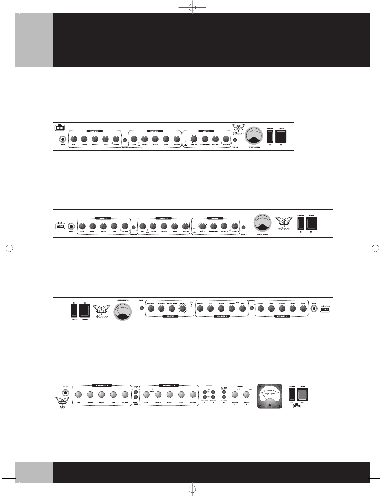
Front Panel Facilities
INPUT - The single jack input socket perfectly
matches passive guitars with its very high
impedance but still retains sufficient
headroom to cope with the output from
modern active instruments.
CHANNEL 1
Channel 1 is intended to be used mainly as a
CLEAN channel.
GAIN - The setting of the GAIN control will
depend very much on the output level of the
guitar being used. For single coil pickups the
sound will be clean for most of the range of
the control with a slight edge only on the
maximum setting. For humbucking pickups
the sound will be clean up to about 12
O’clock with a slight edge being added
beyond this and a definite crunch on
maximum.
TREBLE, MIDDLE, BASS - The Treble, Middle
and Bass controls are a traditional passive
guitar tone network and as such are
interactive in their function. This type of tone
network provides the best overall character
for the guitar, giving a classic, vintage, full-
bodied guitar tone. The values of
components used in the Channel 1 tone
control network have been chosen to best
suit a Clean and Sparkling guitar tone.
VOLUME - Channel 1 has its own Volume
control to allow Channel 1 and Channel 2 to
be easily balanced in level against each other.
It is best in terms of background noise and
overall tone to set this control as high as
possible and the Master control as low as
possible for the required playing volume.
CHANNEL SELECT AND CHANNEL 2 BOOST
(180 Head) - Between Channel 1 and
Channel 2 there are 2 push buttons used for
selecting ‘Channel 1/Channel 2’ and ‘Channel
2 Boost’ from the front panel. If the
footswitch is to be used these push buttons
must be in their OUT position for the
footswitch to operate. Channel 1 or Channel
2 activity is indicated by LEDs above this
push button. An LED above and to the right
of the Channel 2 Gain control indicates
Channel 2 Boost.
CHANNEL SELECT AND CHANNEL 2 BOOST
(40 DSP & 60 DSP Combos, 60 DSP Head) -
Between Channel 1 and Channel 2 there is a
single push button used for selecting
‘Channel 1/Channel 2’ from the front panel. If
the footswitch is to be used this push button
must be in its OUT position for the footswitch
to operate. Channel 1 or Channel 2 activity is
indicated by LEDs either side of this push
button. Channel 2 Boost can only be selected
from the footswitch and an LED to the right
of the Channel 2 Gain control indicates
Channel 2 Boost.
CHANNEL 2
Channel 2 is a very versatile channel and can
be used for styles including fluent solo
playing, power chords, big fat bottom end
muted notes and chords, and screaming
over-the-top lead lines. Due to the dynamics
available on this channel, the guitars’ own
volume control can open up a whole range of
other uses. For instance by winding the
guitar volume back and playing lightly it can
be clean. Hit the string a bit harder and it has
and edge to it. Crank it up to wind into a
singing soloing voice. Muted notes and
chords retain a solid fat bottom end whilst
solo lines can be full and singing with a
saturated, smooth distortion that still retains
a degree of dynamics.
GAIN/CHANNEL 2 BOOST - Channel 2 Gain
control has a vast range available (especially
when used with the Channel 2 Boost facility).
At its lowest setting Channel 2 can be clean.
At its maximum setting it provides a fully
saturated, very high gain, over-the-top lead
tone. We have been very careful to ensure
that the fat bottom end is retained
throughout the entire range of this Gain
control. Channel 2 has been designed to
allow you to set the GAIN control somewhere
in the middle of its range for chords and
general playing. Then you can use the BOOST
to add that extra gain for soloing, over-the-
top fat muted chords or muted note lines.
Adding the BOOST also makes this channel
ideal for tapping styles. If you want balls out,
over-the-top guitar then Channel 2 can be
used with maximum GAIN and BOOST. Be
warned - you will have such a massive degree
of gain that it may be somewhat
uncontrollable.
TREBLE, MIDDLE, BASS - The Treble, Middle
and Bass controls are based on a traditional
passive guitar tone network and as such are
interactive in their function. This type of tone
network provides the best overall character
for the guitar, giving a classic, full-bodied
guitar tone. The values of components used
in the Channel 2 tone control network have
been chosen to best suit a modern, high
gain, saturated guitar sound (with big
bottom end).
It is recommended to use the Treble and
Middle controls set between minimum and
12 O’clock. The bass control can be used set
on maximum if desired.
180 Watt Head Only - Because the 6-tube
output stage of this amplifier reacts so well
with the speakers used, the tonal character
can change drastically from one model of
speaker to another. We recommend the
speakers in Ashdown 4 x 12 cabinets to best
suit this amplifier.
VOLUME - Channel 2 has its own Volume
control to allow Channel 1 and Channel 2 to
be easily balanced in level against each other.
It is best in terms of background noise and
overall tone to set this control as high as
possible and the Master control as low as
possible for the required playing volume.