manuals.online logo
Brands
  1. Home
  2. •
  3. Brands
  4. •
  5. Ashford
  6. •
  7. Weaving Tools & Accessories
  8. •
  9. Ashford TRADITIONAL SPINNING WHEEL User manual

Ashford TRADITIONAL SPINNING WHEEL User manual

Ashford Guarantee
Thank you for purchasing this Ashford product. In the unlikely event there is
any fault in manufacture, please contact the dealer you purchased it from. To
validate the guarantee, please go to www.ashford.co.nz/product-registration
or email us.
Ashford Handicrafts Limited
Factory and Showroom: 415 West Street
PO Box 474, Ashburton 7700 New Zealand
Telephone 64 3 308 9087
Email: sal[email protected]o.nz Internet: www.ashford.co.nz
INSTRUCTIONS
TRADITIONAL SPINNING WHEEL
TDSW-DDSW030920V1
SINGLE DRIVE
DOUBLE DRIVE
ASHFORD TRADITIONAL SPINNING WHEEL
SINGLE DRIVE
TDSW140519V13
ASHFORD TRADITIONAL SPINNING WHEEL
DOUBLE DRIVE
DDSW140519V11
2
3
x1x1
x2
x2x1
x1
x1
x1
x1x1x3
x13
x2x4
x4
x1
x2x2
Real Scale Hardware List
3
4
5
Set the treadle assembly
on the edge of a table.
Insert the conrod joint into
the large slot in the treadle
rail.
Note the crank bearing
faces the back of the
spinning wheel.
Hold the conrod
joint with one hand
on either side of the
treadle rail.
With both hands,
turn the conrod
joint a ¼ turn,
Stretch and slide it
into the small slot
and turn it back a ¼
turn until it clicks
into place.
6
Wax the steel rods in the
treadle rail.
Loosely attach the wheel
support to the side rails
with bolts and barrel nuts.
Then locate the treadle rail
into the holes in the legs.
7
Insert the crank shaft into
the wheel support. Tighten
every bolt extra firmly with
the allen key.
Then remove the crank.
8
Align the wheel and hole in
the crank shaft with the
groove in the hub using a
lazy kate wire.
Carefully tap the hub
pin through the hub
and crank.
Slide the inner shell of the
conrod universal joint onto
the crank until
it clicks into the groove.
Apply a drop of oil to this
bearing and click the
conrod onto the inner
shell of the conrod joint.
Note: The ball bearings are
sealed for life and do not
require oiling.
Slide the inner shell of the
conrod universal joint onto
the crank until it clicks into
the groove.
Apply a drop of oil to this
bearing and click the
conrod onto the inner
shell of the conrod joint.
Note: The ball bearings are
sealed for life and do not
require oiling.
9
SINGLE DRIVE
Step 12 - 21 For Single Drive only. For Double Drive go to Step 22.
Check the angle of the nylon
bearings. Then secure the maid
uprights with screws and washers.
Do not overtighten. The maid
uprights may be twisted to remove
the bobbin. Position the drawing
pin directly beneath the drive
band adjusting knob.
Assemble the Lazy Kate.
Note - the holes with
countersunk holes on each
upright face inwards.
Thread 12 hooks into
the yer.
Assemble the yer unit.
Check the shape of the
nylon bearing on each
maid upright, wax the
dowel ends, then insert
into the correct hole.
Insert the drive belt
adjusting knob into the
maiden bar, turn until the
end just protrudes.
Screw 12 hooks into
the flyer
10
Check the angle of the
nylon bearings. Then
secure the maid uprights
with screws and washers.
Do not overtighten. The
maid uprights may be
twisted to remove the
bobbin.
Position the drawing pin
directly beneath the drive
band adjusting knob.
Place the bobbin, small
end rst, onto the yer.
Then locate the yer into
the bearings. Thread the
screw eye into the side of
the maiden bar, and
screw hook into the
opposite side.
11
Attach the brake band.
Thread it through the
screw eye and then tie the
springs as illustrated.
Put the brake band over
the grooved end of the
bobbin.
Do not over stretch the
springs.
Tie the threading hook to
the front maid upright
with tape.
Attach the yer unit to the
side rails with 2 screws and
washers, do not tighten
yet.
Move the yer unit until
the wheel and large yer
pulley are aligned. Then
tighten the screws.
Check the end of the
adjusting knob is not
protruding beneath the
maiden bar. Then place
the drive belt around the
wheel and large yer
pulley. Tie the drive belt
and cut o the extra.
12
Attach the yer unit to the
side rails with 2 screws and
washers, do not tighten
yet.
Move the yer unit until
the wheel and large yer
pulley are aligned. Then
tighten the screws.
Check the end of the
adjusting knob is not
protruding beneath the
maiden bar. Then place
the drive belt around the
wheel and large yer
pulley. Tie the drive belt
and cut o the extra.
Single drive ratios:
The ratio with the drive
belt around the large yer
pulley is approx.
7:1. To spin a ner yarn
while treadling at the
same speed, move the
drive belt to one of the
cneter pulleys - either 9:1
or 12:1.
To spin a very ne yarn,
move the drive belt onto
the small yer pulley and
retension it. This ratio is
approx. 17:1.
Refer to the Learn To Spin Booklet for more spinning hints.
Happy spinning.
How to insert the polyurethane conrod joints into the conrod.
*This has been pre-assembled in the factory.
13
Assemble the Lazy Kate.
Note - the holes with
countersunk holes on each
upright face inwards.
Thread 12 hooks into the
yer.
Assemble the yer unit.
Check the shape of the
nylon bearing on each
maid upright, wax the
dowel ends, then insert
into the correct hole.
Insert the drive belt
adjusting knob into the
maiden bar, turn until the
end just protrudes.
Check the angle of the
nylon bearings. Then secure
the maid uprights with
screws and washers. Do
not overtighten. The maid
uprights may be twisted
to remove the bobbin.
Position the drawing pin
directly beneath the drive
band adjusting knob.
Screw 12 hooks into
the flyer
DOUBLE DRIVE
Step 22 - 32 For Double Drive only. For Single Drive go to Step 12.
14
Check the angle of the
nylon bearings. Then
secure the maid uprights
with screws and washers.
Do not overtighten.
The maid uprights may be
twisted to remove the
bobbin.
Position the drawing pin
directly beneath the drive
band adjusting knob.
Place the bobbin, small
end rst, onto the yer
followed by the yer whorl.
Then locate the yer into
the bearings.
Thread the screw eye into
the side of the maiden bar,
and screw hook into the
opposite side.
15
This wheel can be used either
double drive or single drive.
When spinning double drive the
brake band is stored around the
back of the maid upright with the
drive band around both the large
flyer and small bobbin pulley.
When spinning single drive the
drive band is around the large
flyer pulley and the brake band
is over either bobbin pulley.
When using the brake band
take care not to over-stretch the
springs.
Attach the flyer unit to the side
rails with 2 screws and washers,
do not tighten yet.
Move the flyer unit until the
wheel and large flyer pulley are
aligned. Then tighten the screws.
15
16
Check the end of the
adjusting knob is not
protruding beneath the
maiden bar. Then place
the drive belt around
the wheel and large
flyer pulley then around
the wheel again and
small bobbin whorl. Tie
the drive belt and cut
off the extra.
17
Ashford Handicrafts Limited
Factory and Showroom: 415 West Street
PO Box 474, Ashburton 7700 New Zealand
Telephone 64 3 308 9087
Email: sal[email protected]o.nz Internet: www.ashford.co.nz
How to insert the polyurethane conrod joints into the conrod.
*This has been pre-assembled in the factory.
SINGLE DRIVE BOBBINS DOUBLE DRIVE BOBBINS

Other Ashford Weaving Tools & Accessories manuals

Ashford TURBO KIT POLYCORD User manual

Ashford

Ashford TURBO KIT POLYCORD User manual

Ashford TREADLE KIT FOR TABLE LOOM STAND User manual

Ashford

Ashford TREADLE KIT FOR TABLE LOOM STAND User manual

Ashford Wild Carder User manual

Ashford

Ashford Wild Carder User manual

Ashford DOUBLE TREADLE KIT User manual

Ashford

Ashford DOUBLE TREADLE KIT User manual

Ashford SKEINER 2 User manual

Ashford

Ashford SKEINER 2 User manual

Ashford DOUBLE TREADLE KIT User manual

Ashford

Ashford DOUBLE TREADLE KIT User manual

Ashford WOODEN UMBRELLA SWIFT User manual

Ashford

Ashford WOODEN UMBRELLA SWIFT User manual

Ashford KNITTERS LOOM SECOND HEDDLE KIT User manual

Ashford

Ashford KNITTERS LOOM SECOND HEDDLE KIT User manual

Ashford KNITTERS LOOM STAND 70cm User manual

Ashford

Ashford KNITTERS LOOM STAND 70cm User manual

Ashford WEAVING FRAME LARGE User manual

Ashford

Ashford WEAVING FRAME LARGE User manual

Ashford KNITTERS LOOM STAND VARIABLE WIDTH User manual

Ashford

Ashford KNITTERS LOOM STAND VARIABLE WIDTH User manual

Ashford PACKER BRUSH User manual

Ashford

Ashford PACKER BRUSH User manual

Ashford WEAVING STARTER KIT User manual

Ashford

Ashford WEAVING STARTER KIT User manual

Ashford Drum Carder User manual

Ashford

Ashford Drum Carder User manual

Ashford DOUBLE TREADLE KIT User manual

Ashford

Ashford DOUBLE TREADLE KIT User manual

Ashford THE WEE PEGGY SPINNING WHEEL User manual

Ashford

Ashford THE WEE PEGGY SPINNING WHEEL User manual

Ashford DOUBLE TREADLE KIT User manual

Ashford

Ashford DOUBLE TREADLE KIT User manual

Ashford WEAVING FRAME SMALL User manual

Ashford

Ashford WEAVING FRAME SMALL User manual

Ashford EDC30 User manual

Ashford

Ashford EDC30 User manual

Ashford KIWI 2 SPINNING WHEEL User manual

Ashford

Ashford KIWI 2 SPINNING WHEEL User manual

Ashford SPINNING WHEEL MAINTENANCE KIT User manual

Ashford

Ashford SPINNING WHEEL MAINTENANCE KIT User manual

Ashford KNITTERS LOOM STAND User manual

Ashford

Ashford KNITTERS LOOM STAND User manual

Ashford RIGID HEDDLE TABLE STAND User manual

Ashford

Ashford RIGID HEDDLE TABLE STAND User manual

Ashford RIGID HEDDLE FREEDOM ROLLER User manual

Ashford

Ashford RIGID HEDDLE FREEDOM ROLLER User manual

Popular Weaving Tools & Accessories manuals by other brands

Beadalon 216S-100 instructions

Beadalon

Beadalon 216S-100 instructions

BEKA Yarn Swift quick start guide

BEKA

BEKA Yarn Swift quick start guide

Beadalon TOGGLE JIG owner's manual

Beadalon

Beadalon TOGGLE JIG owner's manual

Toika Eeva ES Assembly manual

Toika

Toika Eeva ES Assembly manual

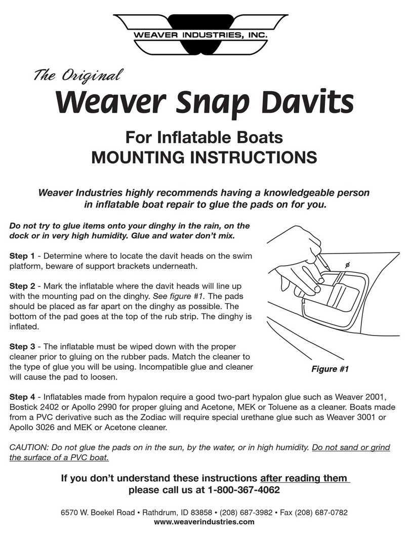
Weaver Weaver Snap Davits Mounting instructions

Weaver

Weaver Weaver Snap Davits Mounting instructions

Beadalon Ring Weaver Tool manual

Beadalon

Beadalon Ring Weaver Tool manual

Xiamen Rizheng Industry Crochet Hook Kit Set Assembly instructions

Xiamen Rizheng Industry

Xiamen Rizheng Industry Crochet Hook Kit Set Assembly instructions

Read Pleaters 24-Row Regular Instruction booklet

Read Pleaters

Read Pleaters 24-Row Regular Instruction booklet

MOKIDA ZM2642501SYL-000-000 user manual

MOKIDA

MOKIDA ZM2642501SYL-000-000 user manual

Artistic Wire Findings Forms 228S-661 instructions

Artistic Wire

Artistic Wire Findings Forms 228S-661 instructions

manuals.online logo
manuals.online logoBrands
  • About & Mission
  • Contact us
  • Privacy Policy
  • Terms and Conditions

Copyright 2025 Manuals.Online. All Rights Reserved.