manuals.online logo
Brands
  1. Home
  2. •
  3. Brands
  4. •
  5. Ashida
  6. •
  7. Other
  8. •
  9. Ashida ADR244A User manual

Ashida ADR244A User manual

ADR244A
Doc ID: ADR244A /PC/01
Rev No.: 01
Page No.: 1 of 11
Introduction:
ASHIDA has designed economical & reliable
Multifunction ADR244A Draw-out/Non draw-
out Protection & Control System. The simple
and compact construction of Aditya series,
ADR244A relay provides integrated
Protection, Control and Monitoring functions
for Induction motors. Draw-out/Non draw-out
versions are available based on ordering
information.
Functional Overview:
Key Protection & Control Functions:
•Draw-out / Non draw-out cabinet
•Two Independent Settings Groups
•Thermal Overload Protection (49)
•Non Directional Phase & Ground Over
Current Function (50/51/51N/51)
•Two Independent Stages for Non
Directional Phase Over Current
Protection
•Two Stages of Non Directional Ground
Over Current Protection
ADR244A
Doc ID: ADR244A/PC/01
Rev No.: 01
Page No.: 2 of 15
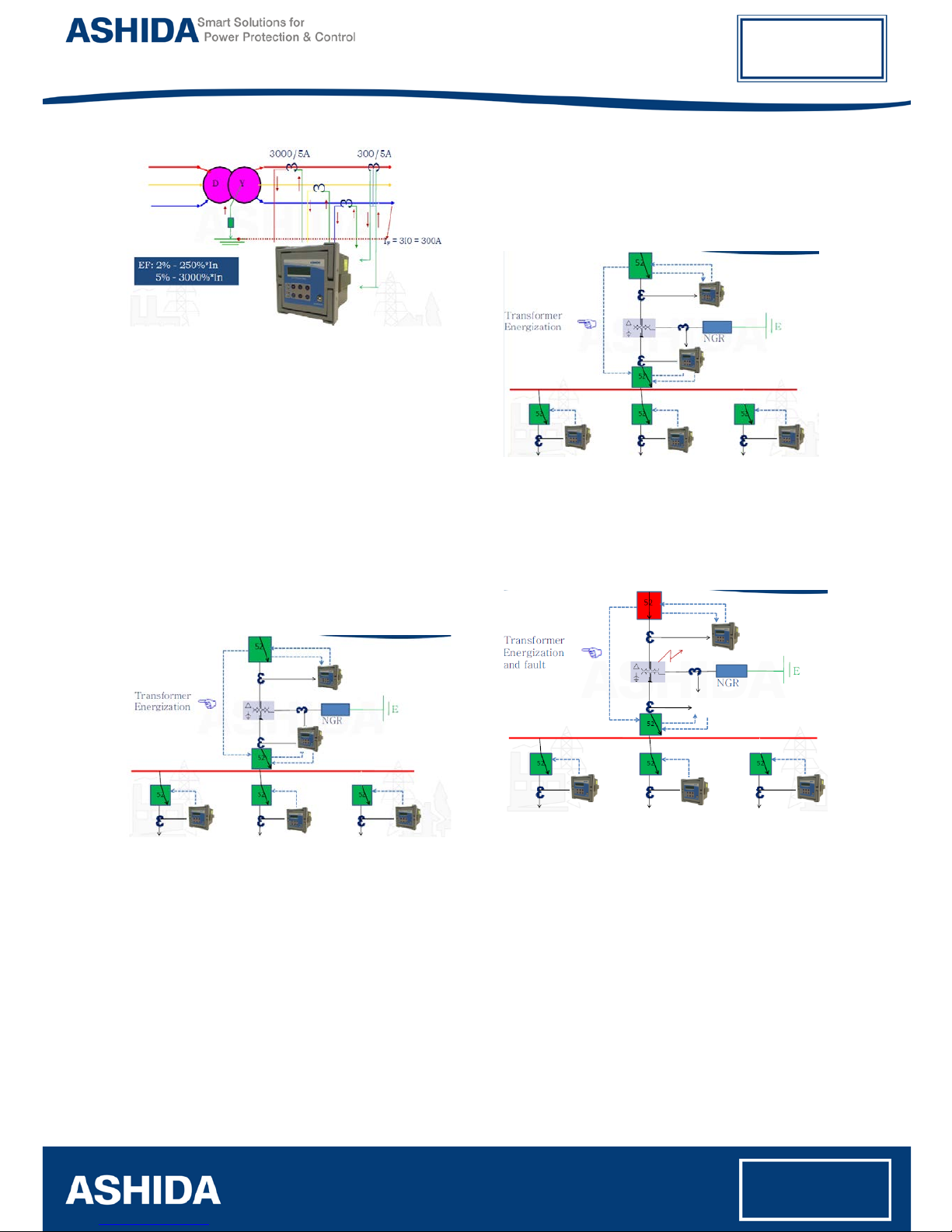
•Internally Derived / Externally measured
Ground Over Current (3I0>) Protection
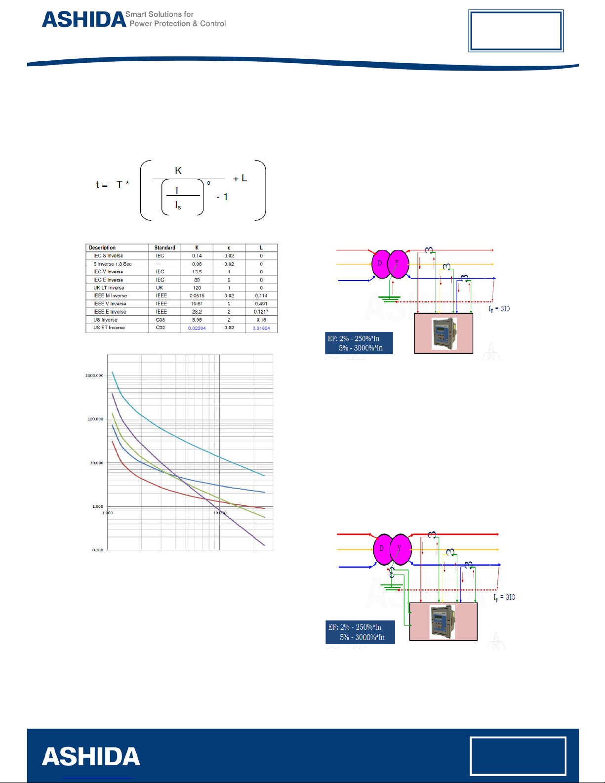
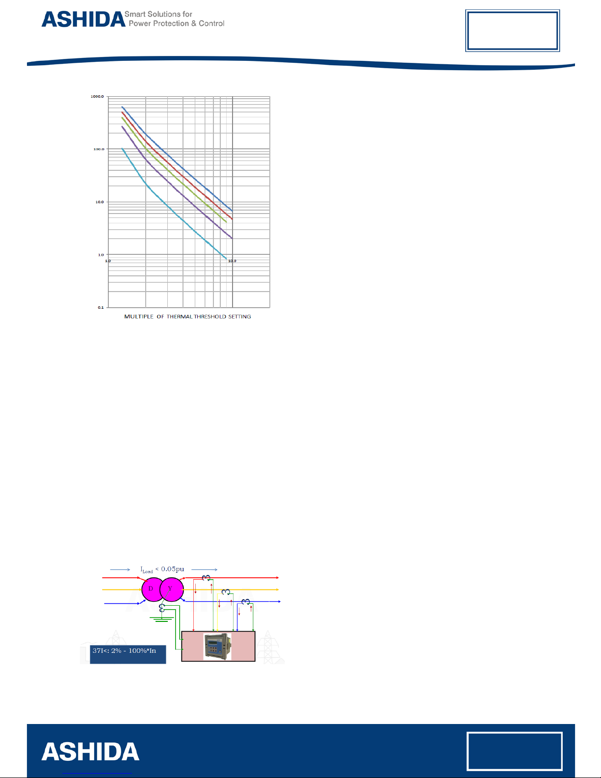
•Inverse time Over Current Protection
(IEC & IEEE curves) + User define curve
•Harmonic blocking and unblocking
feature.
•Cold load pick up.
•High Impedance Restricted Earth Fault
Protection (64R).
•Inverse & Definite time Negative
Sequence Over Current Protection (46)
•Broken Conductor Protection (46BC)
•Phase reversal Protection (47)
•Locked rotor / Motor stall Protection
(50LR)
•Breaker Failure detection (50BF)
•Prolong start Protection (66)
•Too many starts / Number of starts
function
•Trip circuit supervision function
•Programmable Inputs & Outputs
•CB Close / Trip from HMI
•Target LEDs for indication with dual
colours (4 nos.)
•Self Supervision of relay
•Metering function
•Disturbance Recording (10 nos.)
•Event Recording (512 nos.)
•Fault Recording on HMI display (10 nos.)
•Non-Volatile memory
•Fully communicable with IEC standard
open protocol IEC60870-5-103
•Separate communication port for SCADA
Communication
•PC front port communication for
convenient relay settings
•User friendly local operation with key pad
•Liquid crystal display (16x2) with
backlight
•Password Protection.
Software Support:
•Setting Editor.
•Programmable scheme logic Editor.
•Settings upload / download.
•Offline Settings Editor.
•Online Measurement.
•Disturbance analysis.
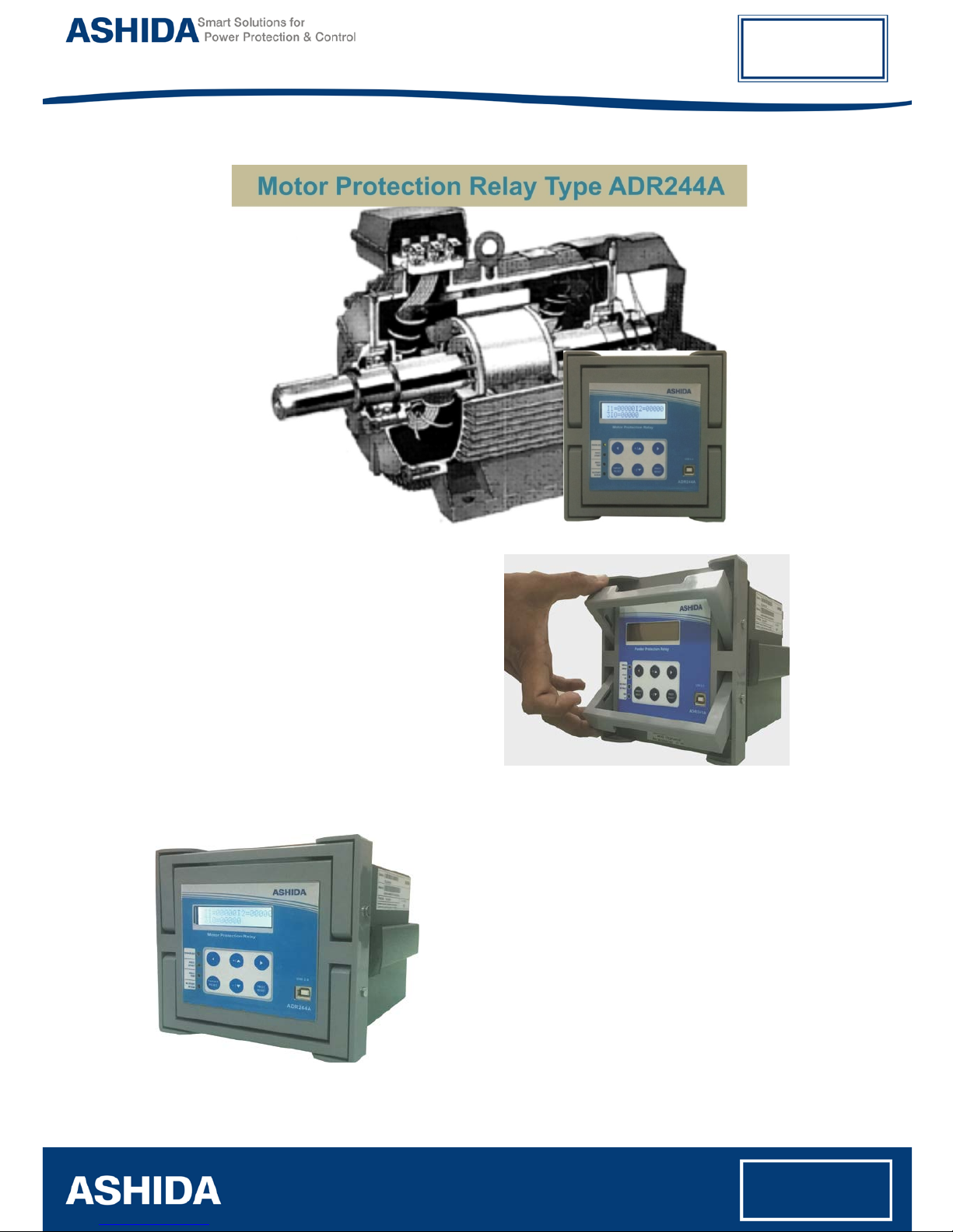
Applications:
ADR244A numerical multifunction relay
designed for induction motor
protection/feeder protection applications.
Relay designed with fast and selective
tripping ensures the stability and availability
of electrical power system.
ADR244A relay apply for protection, control
& monitoring of motor/radial and ring main
feeder to achieve sensitivity and selectivity
on phase, ground faults and unbalance load
conditions.
ADR244A
Doc ID: ADR244A/PC/01
Rev No.: 01
Page No.: 3 of 15
Radial feeder application
The functional overview of ADR244A:
Protection functions Overview
Non Directional Over Current
Protection (50/50N/51/51N):
The core functionality of ADR244A relay is
equipped with multi function feeder
protection. The relay provides Non
Directional phase and ground over current
protection with multiple settings (Two stages
for phase over current and ground over
current) for various power system
applications and wide range of protection
settings. The function is equipped with digital
filter algorithms, providing the rejection of
higher harmonics & DC offset. Selectable
IEC / IEEE inverse time curves & user define
curve with non directional over current
protection will be providing greater
selectivity, flexibility and sensitivity to users
for better relay co-ordinations.
ADR244A relay provides inverse time over
current characteristic for phase and ground
over current elements. Each stage of phase
and ground over current elements are
ANSI Code Description
CLP Cold load pick up
37 Under current Protection
46 Negative Phase Sequence Protection
46BC Broken Conductor Detection
47 Phase Reversal Detection
49 Thermal overload Protection
50
Instantaneous/Definite Time Phase
Over current Protection
51
Inverse Time Phase Over current
Protection
50N
Instantaneous/Definite Time Ground
Over current Protection
50LR
Locked rotor/Motor stall Protection
51N
Inverse Time Ground Over current
Protection
64G
High Impedance Restricted Earth
Fault Protection
66 Number of starts
50BF Breaker Failure
86 Lockout (Trip command)
ADR244A
Doc ID: ADR244A/PC/01
Rev No.: 01
Page No.: 4 of 15
independently settable with inverse time or
definite time characteristic. The following
tripping characteristics are available;
IEC/IEEE Inverse curves for tripping of over current
elements
ADR244A relay provides the inverse time
dropout characteristic (electromechanical
relay reset) for IEEE curves. The output of
protection function shall be reset after
dropout time delay.
ADR244A relay provides two stages of
definite time/inverse time internally derived
zero sequence over current (3I0>) protection
to detects asymmetrical faults in electrical
network. It can apply to over head
transmission line, underground cable, and
feeder. The ground current (3I0>) calculated
from three line currents.
Internally derived residual over current application
ADR244A relay provides two stages of
externally ground over current protection.
ADR244A relay measures ground fault
current through neutral CT input. Externally
ground CT input can also apply for high
impedance restricted earth fault protection or
sensitive ground fault protection through
CBCT.
Externally measured ground over current through neutral
CT
ADR244A
Doc ID: ADR244A/PC/01
Rev No.: 01
Page No.: 5 of 15
Externally measured ground over current through CBCT
Harmonic blocking / Unblocking for
Over Current Protection
(50H/51H/50NH/51NH):
Harmonic blocking / unblocking feature
equipped in ADR244A relay provides stability
on inrush current during transformer
energization. Harmonic blocking/unblocking
feature is independent for each stage of
phase and ground over current protection.
Additional functions (CLP & SOTF):
ADR244A provides the cold load pick up
(CLP) and switch on to fault (SOTF) as
additional functions. User can select the one
of this function for application. Cold load pick
up function provided in relay for multiple
applications. The application of this feature
can be use to avoid wrong operation on
inrush current during transformer
energization without compromising sensitivity
of over current protection.
The ADR244A provides SOTF function to
protection feeder against switch on to fault
condition during feeder/transformer
energization.
Negative Phase Sequence Over
Current Protection (46):
Two independent stages of Definite and
Inverse time Negative sequence over current
protection will be providing back up
protection of over head transmission line /
underground cable / feeder against
unbalanced faults, very high resistive
phase/ground faults and unbalanced loads.
ADR244A
Doc ID: ADR244A/PC/01
Rev No.: 01
Page No.: 6 of 15
Protection can also apply in condition when
there is a very high resistive ground fault and
ground element may not sense the fault
current.
The negative phase sequence over current
element can be programmed as IDMT or
definite time characteristic. ADR244A relay
provides ten selectable IEC / IEEE inverse
curves and one user define curve for each
stage.
Broken Conductor Protection (46BC):
ADR244A equipped with broken conductor
detection protection. Broken conductor
condition can be detected by ratio of
Negative sequence current to Positive
sequence current (I2/I1) provides higher
sensitivity on High resistive fault.
Thermal overload Protection (49):
ADR244A relay provides thermal over load
protection of transformer against over load
conditions. Relay estimate thermal contents
and initiate alarm & tripping if the thermal
contents are higher than the preset value.
Trip time of relay follows the according to the
thermal time constant value set in to relay.
ADR244A
Doc ID: ADR244A/PC/01
Rev No.: 01
Page No.: 7 of 15
Breaker Failure detection (50BF):
If the fault current is not interrupted after a
time delay expired, circuit breaker failures
detected, and execute trip command to
upstream circuit breaker. ADR244A relay
incorporates circuit breaker failure protection
to detect failure of tripping command
execution due to mechanical or electrical
problems in circuit breaker.
Under current detection (37):
ADR244A provide under current protection
with definite time delay option.
Trip circuit supervision (74T):
Any binary inputs for circuit breaker poles
can be used for monitoring the circuit
breaker trip coils including connecting
cables. Relay initiate alarm whenever the
circuit breaker control/DC circuitry gets
interrupted.
The ADR244A is having 4 separate digital
opto-coupler status input which can be used
to continuously monitor heartiness of trip-
circuit.
Relay monitor Trip coil continuity through CB
NO during close condition and through CB
NC during Trip condition. If any discontinuity
observed it generate Alarm signal.
Programmable Inputs, Outputs &
Logic:
The ADR244A relay equipped with 7 nos. of
programmable digital outputs and 4 nos. of
optically isolated digital inputs. All 4 nos. of
digital inputs are the programmable digital
inputs to be configured for desired
applications including trip circuit supervision.
Programmable LEDs and
Pushbuttons:
The ADR244A relay provides total 4 nos. of
target & programmable LEDs with dual
colors indication. The LEDs can be
programmed either through HMI or through
PC software (RTV2 software).
ADR244A
Doc ID: ADR244A/PC/01
Rev No.: 01
Page No.: 8 of 15
Event Recording:
ADR244A relay is providing feature to record
and store 512 nos. of events in non-volatile
memory through internally by protection and
control functions and externally by triggering
of digital inputs, and can be extracted using
communication port or viewed on front of
LCD display. The event shall be trigger on
time stamp through time synchronization or
internal clock setting.
Disturbance recording:
ADR244A relay is provides built in
disturbance recording facility for recoding of
analogue and digital channels. Relay records
10 nos. of disturbances and store in to non-
volatile memory. Disturbance records can be
saved in IEEE COMTRADE format and
same can be analyzed in disturbance
analysis software.
Fault recording:
ADR244A relay is providing fault record
facility. The fault records can be display
either on HMI display or in RTV2 software.
The relay can records 10 nos. of fault
records in non-volatile memory.
Metering:
Online metering feature of ADR244A relay is
providing metering of parameters (i.e. current
magnitude) on HMI display or in RTV2
software.
Independent Protection settings
groups:
ADR244A relay provides two independent
settings groups to allow operate relay on
different power system operating conditions.
IEC 60870-5-103 Protocol:
ADR244A relay provides internationally
standardized protocol for communication via
RS485 port of protection relays. IEC 60870-
5-103 protocol used worldwide and
supported by relay manufacturers.
ADR244A
Doc ID: ADR244A/PC/01
Rev No.: 01
Page No.: 9 of 15
Typical Tests Information:
The Relay Confirm to following standard
Electromagnetic Compatibility Type Test:
Sr. No. Standard Test
1.
High Frequency
Disturbance Test IEC60255-22-1 : Frequency : 1MHz Damped Oscillatory
: Longitudinal :2.5 KV Common Mode,
1 KV Differential Mode
: Duration: sec duration 2 sec.
: On Mains Port.
2. Electrostatic
Discharge Test-
Direct Application
IEC60255-22-2 : IEC 61000-4-2.
: Contact discharge: 2, 4, 6 kV,
: Air discharge: 2, 4 8 KV
: Polarity: both +ve and –Ve polarities.
3. Fast Transient
Disturbance Test
IEC60255-22-4 : Class A
: 4KV; 5/50ns; 5KHz & 100KHz: Repetition rate 300ms;
Both polarities; Ri = 50Ω; duration 1 min.
4.
Surge Immunity
Test
IEC60255-26 &
IEC61000-4-5 : Differential Mode = 2kV
: Common Mode = 4kV
: 1.2/50µs, 8/20µs 5 surges of each polarity
5. Power Frequency
Immunity Test IEC60255-22-7 : Class-A
6. Pulse Magnetic
Field Immunity
Test
IEC61000-4-9 : TEST LEVEL 5, TEST specifications = 1000A/m field
applied in all planes
7. Radiated
Electromagnetic
Field Disturbance
Test
IEC60255-22-3 : 10V/m, Performance Class-A
: 10V/m, freq = 80MHz to 1GHz, 80% AM at 1kHz. SPF
= 80, 160, 380, 450, 900 MHz
8. Conducted
Disturbance
Induced By Radio
Frequency Field
IEC60255-26
: Freq. 150kHz – 80MHz, Amplitude 10 V, Modulation
80% AM @ 1 KHz. SPF = 27 and 68 MHz
9. Power Supply
Immunity Test IEC60255-11 &
IEC61000-4-11 : DC voltage dip:
40% dip 200ms and 70% for 500ms for DC
10 & 20ms without loss of protection for DC
30ms, 50ms, 100ms, 200ms, 300ms, 0.5s, 1s and 5s
with temporary loss of protection for DC
AC voltage dip:
10, 20ms without loss of protection for AC
50ms, 100ms, 200ms, 0.5s, 5s with temporary loss of
protection
ADR244A
Doc ID: ADR244A/PC/01
Rev No.: 01
Page No.: 10 of 15
10.
Conducted &
Radiated
frequency
Emission Test
IEC60255-25 : Conducted
0.15MHz - 0.5MHz, 79dB (microV) Q-
Peak, 66dB
(microV) for average
0.5MHz - 30MHz, 73dB (microV) Q-
Peak, 60dB
(microV) for average
Radiated (3mtr)
30MHz - 230MHz, 50dB (microV) Q-Peak,
230MHz - 1GHz, 57dB (microV) Q-Peak,
Insulation Tests:
11. High Voltage
Test
IEC60255-27 : At 2kV 50Hz between all terminal connected together
and earth for 1 minutes
12. Impulse Voltage
Test
IEC60255-27 : Test voltage: 5KV (peak) 1.2 / 50us,
: Energy :0.5 J,
: Polarity : + ve and – Ve
: Nos. of impulses : 3 positive and 3 negative impulse
: Duration between Impulses : 5 sec.
13. Insulation
Resistance IEC60255-27 : ≥100MΩ@ 500V DC
Environmental tests:
14. Cold test : IEC-60068-2-1
15. Dry heat test : IEC-60068-2-2
16. Damp heat test, steady state : IEC-60068-2-78
17. Change of Temperature : IEC-60068-2-14
18. Damp heat test, cyclic : IEC-60068-2-30
19. Enclosure Protection Test (IP54) : IEC 60529
CE compliance
20. Immunity : IEC-60255-26
21. Emissive Test : IEC- 60255-26
22. Low voltage directive : EN-50178
Mechanical tests
23. Vibration Endurance Test
: IEC 60255-21-1 class 2
: Frequency Range = 10Hz – 250Hz , acceleration. =
2gn
: Sweep rate 1 octave/min; 20 cycle in 3 orthogonal
axis.
24. Vibration Response Test
: IEC 60255-21-1 class 2
: Frequency Range = 10Hz – 150Hz , acceleration. =
1gn
: Sweep rate 1 octave/min; Displacement =0.075mm,
in 3 orthogonal axis.
25. Bump Test : IEC 60255-21-2 Class-1
: 1000 bumps / direction of 10gn peak acceleration and
16ms pulse duration in each of the two opposite
direction per axis as per No. of axes. 3.
ADR244A
Doc ID: ADR244A/PC/01
Rev No.: 01
Page No.: 11 of 15
26.Shock Withstand Test : IEC 60255-21-2 Class-1
: 3 shocks of 15gn peak acceleration and 11ms pulse
in each of two opposite direction. No. of axis : 3
27. Shock Response Test : IEC 60255-21-2 Class-2
: 3 shocks of 10gn peak acceleration and 11ms pulse
in each of two opposite direction. No. of axis : 3
28. Seismic Test : IEC 60255-21-3 Class-2
: Sweep 1/Axis (@a sweep rate of 1 octave/minute)
vibration in the frequency range (5-
35 Hz) at
displacement X-axis: 7.5mm, Y-axis: 3.5mm amplitude
of 3.5mm with acceleration of X-axis: 2gn, Y-axis: 1gn.
Note: Type test report is available on request
ADR244A
Doc ID: ADR244A/PC/01
Rev No.: 01
Page No.: 12 of 15
ADR244A
Doc ID: ADR244A/PC/01
Rev No.: 01
Page No.: 13 of 15
ADR244A
Doc ID: ADR244A/PC/01
Rev No.: 01
Page No.: 14 of 15
ADR244A
ASHIDA ELECTRONICS PVT LTD. All rights reserved. All brand or product
names appearing in this document are the trademark or registered
trademark of their respective holders. No ASHIDA trademarks may be used
without written permission.
The information in this document is provided for informational use only and
is subject to change without legal notice. ASHIDA ELECTRONICS PVT
LTD. has approved only the English language document.

Popular Other manuals by other brands

BeoPlay H9i quick start guide

BeoPlay

BeoPlay H9i quick start guide

HP v260w Specifications

HP

HP v260w Specifications

Insignia NS-DH70WH9 user guide

Insignia

Insignia NS-DH70WH9 user guide

Airaid 450-331 installation instructions

Airaid

Airaid 450-331 installation instructions

EMG MARTY FRIEDMAN MF Series Installation information

EMG

EMG MARTY FRIEDMAN MF Series Installation information

Datafox ZK-Box V4 manual

Datafox

Datafox ZK-Box V4 manual

Crestron TPS-FPAR2000L datasheet

Crestron

Crestron TPS-FPAR2000L datasheet

ABB Relion RER615 installation manual

ABB

ABB Relion RER615 installation manual

Dog Guard DG9000 Installation and Training Guide

Dog Guard

Dog Guard DG9000 Installation and Training Guide

Jetline CWF-50A Operation manual

Jetline

Jetline CWF-50A Operation manual

Aero-motive 14131 installation instructions

Aero-motive

Aero-motive 14131 installation instructions

JRC JCY-1800 - installation manual

JRC

JRC JCY-1800 - installation manual

Lakes QUADRANT Installation & maintenance instructions

Lakes

Lakes QUADRANT Installation & maintenance instructions

SparTag T-75 Software Operation manual

SparTag

SparTag T-75 Software Operation manual

LAMBORGHINI PAC 120 - SCHEMA manual

LAMBORGHINI

LAMBORGHINI PAC 120 - SCHEMA manual

Suki Suki 12 user manual

Suki

Suki Suki 12 user manual

Bontrager TRACK WHEELS Owner's manual supplement

Bontrager

Bontrager TRACK WHEELS Owner's manual supplement

Red Sea MAX S-Series manual

Red Sea

Red Sea MAX S-Series manual

manuals.online logo
manuals.online logoBrands
  • About & Mission
  • Contact us
  • Privacy Policy
  • Terms and Conditions

Copyright 2025 Manuals.Online. All Rights Reserved.