GlassCrafters Equalis series User manual

Frameless By-Pass Shower/Tub Enclosure
Installation Instructions
The following instruction sheet is for the installation of the models:
SHOWER ENCLOSURES: DS-48T-38 45”- 48”w X 76”h , DS-54T-38 51”- 54’w X 76”h , DS-60T-38 57”- 60”w X 76”h , DS-66T-38 63”- 66”w X 76”h
TUB ENCLOSURES: DT-60T-38 57”- 60”w X 66”h , DT-66T-38 63“- 66”w X 66”h
All Un ts are ava lable n three fin shes:
Brushed Sta nless Steel (BSS), Pol shed Sta nless Steel (PSS), Pol shed Chrome Alum num (CHA) or Iron Black (IBK)
Ple se use extreme c re while unp cking nd h ndling your Gl ssCr fters’ Shower or Tub Enclosure. If you need
repl cement p rts or h ve inst ll tion questions nd to report ny d m ge cont ct our Gl ssCr fters’ customer service
te m t sales@glasscraftersinc.com or 888-683-1362, Mond y thru Frid y from 8:00 m to 5:00 pm (EST).
Inst ll tion sh ll be m de ccording to m nuf cturers’ instructions nd dr wings .
Gl ssCr fters recommends the inst ll tion be performed by tr ined inst ller.
Revised110/2018
WARNING: TO INSTALL ON CAST IRON, FIBERGLASS, ACRYLIC OR RESIN TUB OR SHOWER BASE
Check with the tub or shower base manufacturer to determine the tooling required.
Shower Enclosure Tub Enclosure
INSTALLING
THESE UNITS
REQUIRES
2 PERSONS
FOR BEST RESULTS
GlassCrafters rec mmends the installati n be
perf rmed by a trained installer.
SA E THESE INSTRUCTIONS
FOR FUTURE REFERENCE
EQUALIS Series Frameless By-Pass
Sh wer/Tub encl sures are als
available with a Return Panel.
Separate Installati n Instructi ns f r the
Return Panel are supplied in the Return Package.
GLASSCRAFTERS, INC
193 Veter ns Blvd., C rlst dt, NJ 07072
1+(888) 683-1362 -- (F x) 201-525-1117
s les@gl sscr ftersinc.com

Tools Required - For installation of
Your Shower Enclosure
Safety glasses
Measuring tape
Pencil
Hack saw or chop saw
(for stainless steel)
Miter Box or Square
evel
Electric Drill
Center Punch
Rubber Mallet
1. Header Wall Brackets 2
2. Header 1
3. Inside Roller Door Stop 2
4. Outside Roller Door Stop 2
5. Glass Door 2
6. Inside Door Roller Assembly 2
7. Outside Door Roller Assembly 2
8. Flat Head Screws, #8 x 1 1/4” 7
9. Plastic Wall Anchors 7
10. Center Guide 1
11. Roller Adjustment Wrench 2
12. Curb Dam 1
13. Center Guide eaf 4
14. Hex Key Set (4) 1
15. Towel Bar Assembly 2
16. “A” Vinyl /Bumper 2
17. Clear “H” Vinyl 1
Parts Description
ITEM NO. DESCRIPTION QTY.
Drill bit, 5/16” masonry
(for installation on ceramic
tiles or marble)
Power screwdriver
#2 phillips screwdriver
Caulking gun
Cutting Pliers
Suction Glass ifters
(rated for more than 100 lbs)
WARNING: TO INSTALL ON CAST IRON,
FIBERGLASS, ACRYLIC OR RESIN TUB
OR SHOWER BASE
Check with the tub or shower base
manufacturer to
determine the tooling required.
ASSE BLY AND INSTALLATION INSTRUCTIONS:
GlassCrafters recommends the installation be performed by
a trained installer.
• Read the manual and become familiar with the steps
involved in installation.
• This product requires Two Persons for safe installation.
• Always wear safety glasses during this installation.
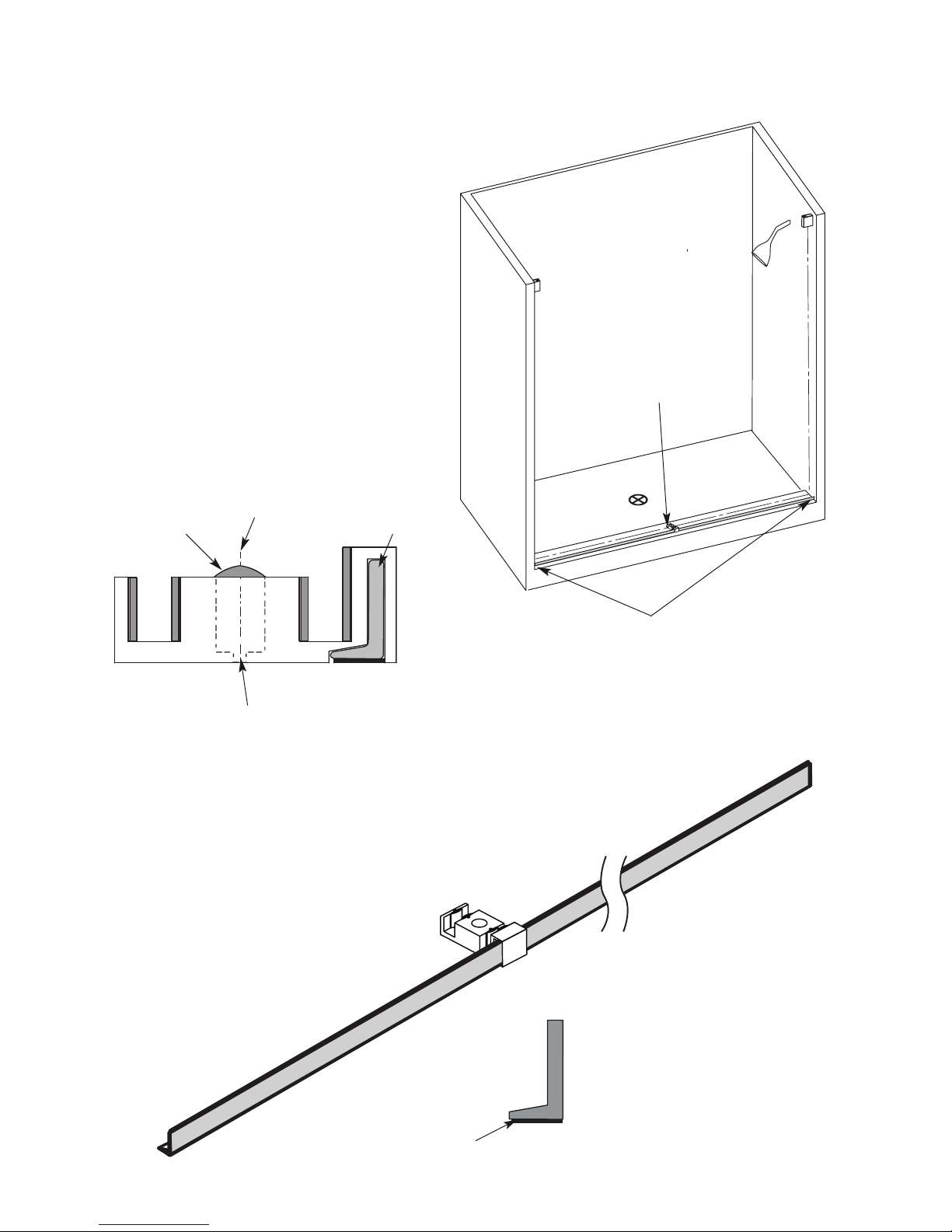
• The proper dimensions for this installation were submitted
at the time of order. The two doors may overlap to
accommodate minor smaller opening. One end of the Header
many be cut with a Hacksaw for stainless steel, but it must fit
completely in the Header Wall Brackets for a safe installation.
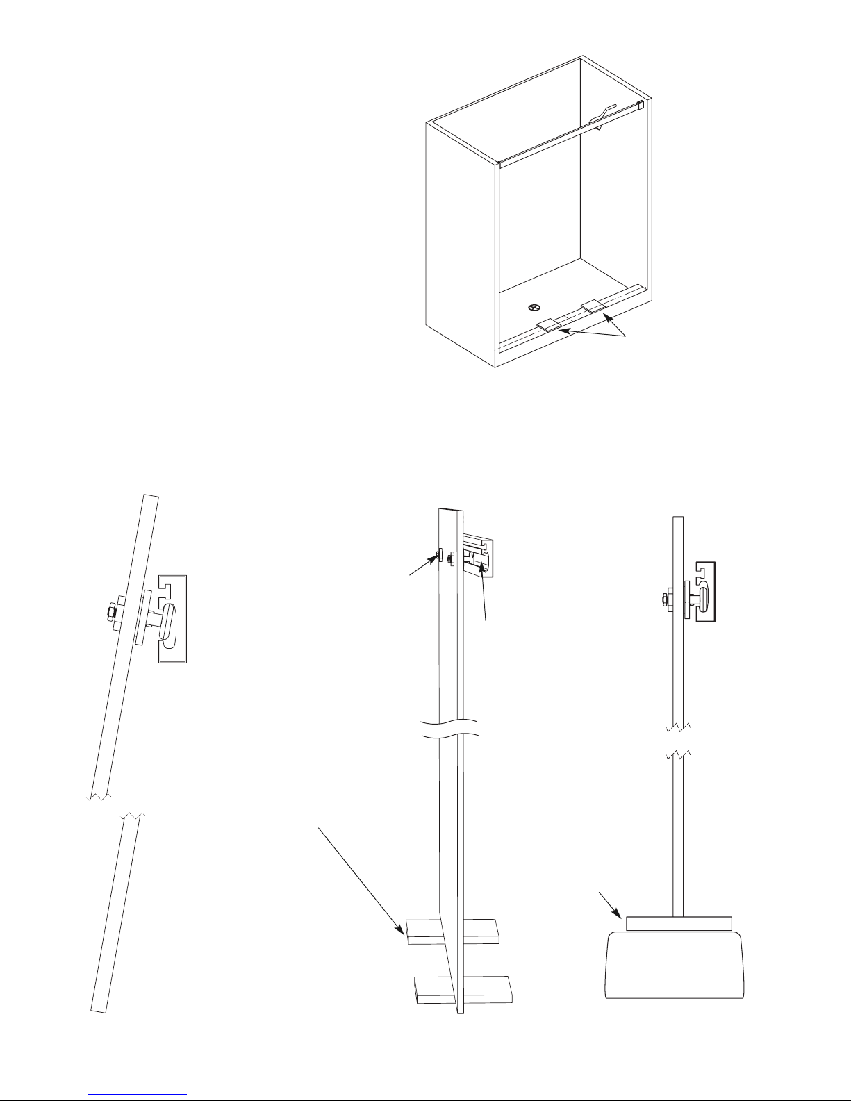
• When installing any mechanical parts through the
pre-drilled holes in the glass door and panel be sure to use
the gaskets and bushings supplied between any metal
element and the glass. Do no overtighten any fittings.
• If the installation is over ceramic tiles the wall Jamb must lay
flat on these tiles for the entire height of the unit.
• Silicone Sealant is used to seal some parts during
installation.
2
CAUTION: Risk of injury or product damage. Do not attempt to cut tempered glass.
I PORTANT! Children should be supervised at all times while in Tub/Shower Enclosure.
I PORTANT! Never use Door Handle to support yourself. This is for towels or wash cloths only.
PLEASE STOP THE INSTALLATION AND CONFIR WITH FACTORY IF THE ACTUAL NU BER OR TYPE OF PARTS IS DIFFERENT.
90°
B
90°
THIS ANUAL IS FOR INSTALLATION OF THE EQUALIS SERIES™
FRA ELESS -BYPASS FOR SHOWER STALL OR TUB ENCLOSURES
THE EQUALIS SERIES™ FRA ELESS -BYPASS IS ALSO
AVAILABLE WITH RETURN
FOR BOTH SHOWER STALL OR TUB ENCLOSURES.
THE RETURN CONFIGURATION HAS A
SEPARATE ANUAL FOR THE RETURN.
TUBSTALL

I PORTANT: Determine if your Tub/Shower Stall
Enclosure ledge is Level and Walls are plumb.
If they are out of Level/Plumb, by more than 3/8”,
STOP! and call Customer Service.
The Phone number is 1-888-683-1362 .
If they are evel/Plumb, or out of Plumb for less than
3/8” proceed with installation.
SPECIAL NOTE:
2 3/4” INI U CURB WIDTH REQUIRED.
When ordering replacement parts,please specify the
odel Number, Item Number & Part Description.
Save these Installation Instructions For
Future Reference.
Write your Dealer information down on Notes Section.
Ask your Dealer for JOB OG NUMBER ( xxxxxx-xxx)
referencing to your shower enclosure.
Parts
3
Unpacking: • A box Cutter should not be use to open any box.
• Please remove all staples from the box prior to unpacking metal and glass.
• Stand Panels upright on a cushioned base, such as a piece of carpet or towel.
• Never place glass directly on hard surfaces.
• Any assembly that requires the panel to lay flat must be on a cushion surface.
I PORTANT: Read all instructions carefully and become familiar with all parts before installation.
1
Header
Bracket
2
Header
3
Inside Door
Stop
4
Outside Door
Stop
6
Inside Door
Roller
8
Flathead Screw
9
Anchor
7
Outside Door
Roller
16
”A” Vinyl
15
Towel Bar
14
Hex Key Set
13
Center Guide
Leaf
12
Curb Dam
(From Inside)
11
Roller Adjustment
Wrench
10
Center Guide
(From Inside)
17
”H” Vinyl
(Splash Guard)
5 Glass Doors
Header
(Section view)
VERY I PORTANT -- If your installation includes a
RETURN PANEL consult the instructions and part list
for the Return Panel and follow those steps.

4
STEP 1B. Determine the Level and centerline
of the Curb. (Work from high side first.)
Determine the level of the curb and mark the “high” side
(A maximum of 3/8” out of level is acceptable.)
Draw a pencil line side to side on the center line of the
Curb. Draw a line front to back on the exact center of
the curb.
STEP 1. Determine the Plumb Condition of the
opening: Use a level to determined that the enclosure
is plumb on both sides. If any side is out of plumb more
that 3/8” it will make the adjustment of the Glass Doors
complicated.
Detail 1A Detail 1B
Detail 1C — Extend the centerline from the high side of the curb on the wall
Determine the high side
Find the Midpoint of the Curb and mark
a pencil line from front to back
Find the Centerline of the curb
and mark a pencil line from left
to right.
With a plumb line or a level
extend the center line to the
height of the header (either
66” or 76”)
76” high unit
66 high unit

5
Detail 2B
Detail 3A
Detail 3B
Use a level to determine that the dotted line
on the template is perfectly vertical and
matched with the marked centerline on the
curb.
Mark the correct height for the top of the
bracket.
STEP 2. Using the penciled centerline on the wall use
a level to recheck the exact vertical position. Mark the
top height for the bracket at 66” or 76” as per your
unit. Place the bracket in position on the centerline
and mark holes for the wall bracket.
76” high unit
66 high unit
NOTE: oosen the set screws
and the bracket top slides out
for installation
After drilling the holes for the Header Bracket,
add silicone to each hole and put the anchors in
place.
FOR ODELS USING A RETURN PANEL:
Stop here and read the installation manual for the
RETURN PANEL. The Return panel and supporting
elements must be installed before proceeding.
STEP 3. Drill and install the install the Header Wall
Bracket Use the Flathead Screws and and anchors as
supplied.

6
STEP 4. Position for second Header Wall Bracket -- .
Extend the pencil centerline from the marked center
line on the curb and use a plumb or level to determine
the correct vertical position.
Detail 4A
Detail 5A
Detail 5B
Detail 5C
NOTE: With a plumb or
level create an extension
of the curb centerline on
the wall in the same
manner as shown in
Detail 2B.
Using a level and
the template
mark the location
for the second
Header Bracket.
Drill the holes and fasten the left
side Header Bracket to the wall.
To check that the header
is exactly level hold the
bracket and the header in
place on the template and
check with a level.
I PORTANT NOTE: The header must be exactly
level to insure the correct operation of the
doors. If the header is out of level the doors will
not close properly.
STEP 5. If the curb is out of square, the location
of the second header bracket will not align as
level. The difference will be the out-of-square
measure at the curb.
Use a level to determine the exact position as
follows:
• Place the second side wall Header Bracket on
the Header — loosen the set screws to slide
onto the Header —and place the other end of
Header in the installed Wall Bracket.
NOTE: When placing the header into the bracket squeeze each
end to be sure that the stainless steel cladding is tight against
the aluminum header bar to a oid bending and
damaging the header finish.
• ower the Header with the installed Wall
Bracket into position as aligned centered on the
marked vertical centerline.
• Use a level to determine the correct level
position for the second Wall Bracket.
• Mark the top and outside of the Wall Bracket
and then remove the header and place the Wall
Bracket in position.
• Mark for the installation holes.
• Drill and install the second Wall Bracket.
After drilling
the holes for
the Header
Bracket add
silicone to each
hole and put
the anchors in
place.
Fasten with the
flathead screws
supplied.
NOTE: Install the Header after Steps #6 & 7 in
Step #8 on page 8.

7
STEP 6. easure for the Curb Dam
The Curb Dam must be cut to size. Measure
from the inside edge of opening. Cut it and
test fit with the Center Guide . Align the Cen-
ter Guide screw hole with the marked cenert-
line. Mark the position for the Center Guide
screw hole. Install later in Step #12
STEP 6B. Mark the position of the Curb Dam
with pencil lines at each end on the wall and
across the outside edge of the Curb Dam on
the base. Measure at both ends of this pencil
line for the Curb Dam to determine that it is
exactly parallel to the center line for the
Center Guide. The offset from the centerline
should be 1 15/32 (1.4686”).
The Center Guide and the Curb Dam must be
installed at the same time. (See Step 12).
Detail 6A
NOTE: Do not install the Center Guide
at this time. (See Step 12)
Detail 6B— Center Guide and
Curb Dam Assembly
(Shown from outside view)
Detail 6C - Curb Dam
(Shown end view)
Double Faced Tape
Mark the position of the Curb Dam with pencil lines
at each end on the wall and across the outside edge
of the Curb Dam on the base.
Mark the Center
Guide screw hole
Curb Centerline
Remove this cap for
access to mark the
hole location
Mark this hole for later drilling
OutsideInside
Curb Dam

8
PRE-ASSE BLE THE HEADER:
STEP 7. Slide the inner stops into the bottom channel in
the header with the square end facing the wall end of the
header. Slide the outer stops in the top channel of the
header near each end of the header. DO NOT TIGHTEN
THE SCREWS FOR STOPS AT THIS TIME.
HH
STEP 8. Install the header in the wall brackets, insert
the brack covers and tighten the set screws. Be sure the
header rest firmly on the bottom of the bracket and
that it is exactly level.
Detail 7A
Shows inside
of the Header
Detail 8A
Detail 8B
Detail 8C
Outer Door Roller Stops
Inner Door Roller Stops
to each end of the
header and tighten just
enough to hold in place.
Outer Door Roller Stops to
each end of the header and
tighten just enough to hold
in place.
Tighten
Set Screws

KK
9
JJ
PRE-ASSE BLE THE INNER DOOR:
(Note: the Inner Glass Door has and identifying label.)
STEP 9. Install both of the inner glass door Roller Assemblies
on the door. The each assembly has twin rollers that face
out. Do not tighten the back screws on the assembly. The
rollers must sit tight on the glass but the back screw must
only be hand tight.
Detail 9D
Detail 9C -- Top View
Detail 9D -- Section View
Detail 9A
Install the inner rollers
on the inner glass door.
Do not tighten the back screws
of inner roller assembly.
The roller assembly must
be loosely fixed on glass at this
time.
Detail 9B -- Inner Roller Assembly (Exploded View)
Detail 9C -- Inner Roller Assembly
(as supplied assembed)
Do not tighten the back screws
of inner roller assembly.
The roller assembly must
be loosely fixed on glass at this time.
Inner Glass
Inner Glass
Front Plate of
the Roller

10
INSTALL THE INNER DOOR:
STEP 10. Create two cushioning blocks for the inner
door installation. Use the cardboard from the box and
cut, tape and assemble two 3/8” to 1/2” thick 6” x 6”
blocks.
STEP 11. The inner door is installed from the
inside with the twin rollers facing out. ift the door
over the curb and angle it to the inside. Working
from each side of the door lift and tip it (about 15 to
25 degree angle is necessary) so that the rollers on
both sides of the door move up and into the desig-
nated channel. As you lower the door into the track
move the position to vertical and rest on the
cushioning blocks on the curb. Tighten the back
screws of the rollers with the wrench supplied.
Remove the cushion blocks.
From the inside-- ift the inner door with
rollers assembled and set the rollers inside the
groove on the inner side of the header in the
manner shown.
The glass door must be angled - 15-25 degrees.
The rollers must go in and up into the upper
cavity of header. Swing the bottom of glass
forward to parallel it with header until both
rollers are inside the groove bring the glass
and rest it on the cushion blocks on the curb.
When the glass door is
resting on the blocking
and rollers are inside the
header use the Roller
Wrench to tighten the
screws on the back of the
rollers.
After tightening the screws
with the Roller Wrench
remove the blocks under
the doors.
Cut 4 strips of cardboard 6"x 6”
and tape 2 of them together
making 3/8”-1/2” thick 6” x 6”
blocks. Make 2 blocks out of 4
strips.
Set two 3/8”-1/2”
blocks (not provided)
on curb top (as
shown). Use the
cardboard from the
boxes that glass was
shipped in for the
blocking.
Detail 10A
Detail 11A Detail 11C
Detail 11B
Move the inside stops to the ends of the header and
temporarily snug them in place to prevent the Glass
from hitting the wall during installation.
Final stop adjustment is done in step 18.
(NOT SHOW HERE)
Inner and Outer Door Roller
Stops must be in the end of
the header and tightened
just enough to hold in place.

11
STEP 12. easure to Position the Curb Dam
Assemble the Curb Dam (as cut to size) with the Center
Guide. Slide the Center Guide under the Inner door. (Be
sure to align the Center Guide with the mark for the
screw hole). Be sure to use the marked
position of the Curb Dam following the pencil lines at
each end on the wall and across the outside edge of the
base. Tape into temporary position with duct tape. Test
the Inner door for smooth movement holding the
Center Guide in position.
STEP 13. ift out the parts and drill the hole for the Cen-
ter Guide. Insert a small amount of silicone and the An-
chor. Wipe the base clean of all debris. Clean surface
with denatured alcohol (Do Not remove the pencil
marks for the outside of the Curb Dam.)
Centerline
Pencil line for
Curb Dam
position
Position the Curb Dam
pencil mark for outside
edge 1 15/32” from the
center line.
Detail 12C— Section View Detail 12D — Center Guide Detail
Detail 12B— Top view
Detail 12A
Mark the holes, drill and
install the anchor.
Shows the Curb
Dam within the
Center Guide with
Double Faced Tape
Guide eaf
Inside view

12
Detail 14A
Detail 14B --
View from Inside
Detail 14C --
View from Outside
Slide the Center Guide under the Inside Door and
position over the drilled hole . Screw into place
with the Flathead Screws provided.
Inside Door
STEP 14. Turn the Curb Dam over. Remove the film
covering the double faced tape. Carefully align and
place on the curb to the pencil marks. Fit the Center
Guide into place sliding it over the Curb Dam and
under the Inside Door.
Retest the movement of the Door, side to side
through the Center Guide. Screw the Center Guide
into place and press the Curb Dam firmly into
place.
Double Faced Tape
Replace the plastic
cover for the Center
Guide

13
INSTALL THE OUTER DOOR:
(Note: the Outer Glass Door has an identifying label.)
STEP 15. Install the Outer Roller assemblies in the
predrilled holes in the outer glass door.
• The Roller assemblies go on the inside of the door.
• Be sure to use the plastic washers fittings as supplied in
the assembled Rollers to protect the glass from metal
elements.
•Tighten the Roller into position from the outside of the
door. Do not overtighten as the final adjustment of the
door operation may be required.
• BE SURE THAT THE “ANTI- IFT” SCREW GROOVES IN THE
CENTER OF THE RO ER -- AS VIEWED FROM THE INSIDE--
ARE PERPENDICU AR TO THE EDGE OF THE G ASS. (See
Detail 15C)
• Do not install the Outer Roller Cap or the Outer
Roller Back Plate and screw until after the doors are
finally adjusted.
90.00°
Detail 15B Detail 15C As viewed from the
inside of the door
BE SURE THAT THE “ANTI- IFT” SCREW GROOVES IN THE
CENTER OF THE RO ER -- AS VIEWED FROM THE INSIDE--
ARE PERPENDICU AR TO THE EDGE OF THE G ASS.
Do not install the Outer Roller Cap or the Outer Roller
Back Plate and screw until after the doors are finally
adjusted.
Outer Roller Cap
Outer Roller Back Plate
Anti- ift Screw Grooves
Plastic Washers
and Fittings
Detail 15A - Exploded View of
the Outer Roller Assembly

STEP 16. ift the door straight up and lower it into position
with the Roller on the header with the bottom edge of the
glass inside the guide on the curb. Test the movement left to
right to be sure the doors move freely and are not scaping on
the bottom guide.
Adjust the doors using the roller adjustment wrenches, as supplied, as shown
in the illustrations Detail 16C for the inside door rollers and Detail 16D for the
outside door rollers. After they are adjusted for smooth operation tighten the
inner door roller screws and place the Inner Roller Cap Detail 16E over each
Inner Roller. Fix the Inner Roller Cap in place with the set screw. Install the
Outer Roller Cap Detail 16F and the Outer Roller Back Plate as shown in the
Illustrations. Fix the Outer Roller Caps and Back Plates in place with the set
screws.
14
Detail 16B -- Side View
Detail 16E
Install the Inner
Roller cap
Detail 16F
Install the
Outer Roller
Cap
and the
Back Plate
Detail 16DDetail 16C
Detail 16A -- Front View
ift the door
straight up and
lower it into posi-
tion with the Roller
on the header with
the bottom edge of
the glass inside the-
center guide on the
curb.

STEP 17.Install the “A” Vinyls on the wall side of
each door. The “A” Vinyls ae supplied oversize and
should be measured against the glass and cut to size.
An “H” Vinyl is also supplied to be installed on the
inside edge of the Inner door to be used only if the
shower sprays into the gap between the doors.
STEP 18. Adjust the Door Stops: Working from the inside of the
shower, bring both doors to the closed position where the Vinyls are
touching the walls on both sides. Move the Inner and Outer Stops into
the desired positions where the “A” Vinyls are just slightly compressed.
Tighten the screws for the door stops for this closed position.
Carefully move the doors to the opposite ends of the header,
leave 1/2” to 1” gap between this position and the wall and tighten
the second set of stops at this end of the header for both doors.
15
Detail 17A -- “A” Vinyl
Detail 17C -- Shows“A” Vinyl in place
Detail 18A — Shows Doors in closed Position
Detail 18B -- Shows Doors fully open with 1/2” gap to the wall
Detail 17B -- “H” Vinyl
Only use if needed as a splash
guard between the doors
Vinyls should be
touching the wall.
1/2” gap between
the glass door
and the wall.
Move the outer edge Stops to this
position and tighten in place.
Tighten both Inner and Outer Door
Stops on both doors at this poistion at
the the ends of the Header in to prevent
the glass doors from hitting the wall.

Revised 10/2018
GLASSCRAFTERS, INC
193 Veter ns Blvd., C rlst dt, NJ 07072
1+(888) 683-1362 — (F) (201) 525-1117
s les@gl sscr ftersinc.com
Cleaning Recommendations:
Never use abrasive cleaners or cleaners
containing ammonia. This may cause
chemical damage .
For cle ning, we recommend using
mmoni free Spr yw y br nd gl ss
cle ner, which is v il ble t v riety
of ret il outlets.
www.spr yw yinc.com/content/gl ss-cle ner
16
CLEANING INSTRUCTIONS:
Never use scouring powder, pads or sharp instruments
on metal work or glass panels. We recommends the use
of a squeegee after each shower to eliminate the water
spots on the inside of the glass panels. An occasional
wiping down on the glass panels and metal parts with a
mild detergent , diluted in water, is all that is need to
keep your shower/tub enclosure looking brand new.
EQUALIS Series™ Models
Catalog Number PSS - Polished Stainless Steel
BSS - Brushed Stainless Steel
CHA - Polished Chrome Anodized
IBK - Black Iron
Shower Enclosures
Met l Finish.
DS-48T-38 PSS
DS-48T-38 BSS
DS-48T-38 CHA
DS-48T-38 IBK
DS-54T-38 BSS
DS-54T-38 PSS
DS-54T-38 CHA
DS-54T-38 IBK
DS-60T-38 PSS
DS-60T-38 BSS
DS-60T-38 CHA
DS-60T-38 IBK
DS-66T-38 PSS
DS-66T-38 BSS
DS-66T-38 CHA
DS-66T-38 IBK
Tub Enclosures
Met l Finish.
DT-60T-38 PSS
DT-60T-38 BSS
DT-60T-38 CHA
DT-60T-38 IBK
DT-66T-38 PSS
DT-66T-38 BSS
DT-66T-38 CHA
DT-66T-38 IBK
NOTES:
odel Number… ___________________________________
Dealer ________________________________________________
Job Log # _____________________________________________
STEP 19. Install the Towel Bar Assembly (See Detail 19B)
on both the inside and outside of each door as shown in
the top view below (Detail 19A).
Detail 19 A-- Top View
Detail 19B--
Parts assembly
Table of contents
Other GlassCrafters Other manuals
Popular Other manuals by other brands

Aodyo Instruments
Aodyo Instruments Sylphyo Link user guide

F-SECURE
F-SECURE MOBILE SECURITY - QUICK GUIDE FOR BUSINESS Getting started

Nedap
Nedap COMBI-BOOSTER installation guide

hopf
hopf 8029NTS-V2/GPS Technical manual

Iron-Fence Shop
Iron-Fence Shop STRONGHOLD IRON installation guide

Basement Systems
Basement Systems Sani Dry CSB Installer's & owner's manual