ASI 0198-1 Service manual

1PLEASE CAREFULLY READ THROUGH THIS MANUAL BEFORE USING THE PRODUCT. OBSERVING ALL SAFETY INFORMATION, WARNINGS AND CAUTIONS WILL PROTECT YOURSELF AND OTHERS . PLEASE KEEP INSTRUCTIONS FOR FUTURE REFERENCE.Operating Instructions and Parts Manual Hand DryerSurface-mounted High-Speed hand dryer www.americanspecialties.comAMERICAN SPECIALTIES, INC.441 Saw Mill River Road, Yonkers, NY 10701 (914) 476-9000MODEL # 0198-1MODEL # 0198-2ITEM CATEGORYOperating Voltage, 0198-1Operating Voltage, 0198-2Output Warm Air Volume Output Warm Air Temp Output Air SpeedSound PressureMotor TypeMotor Thermal ProtectionHeater ElementHeater Thermal ProtectionDrying TimeCircuit OperationSensor RangeTiming ProtectionTiming DurationCover TypeCover FinishNet WeightShipping WeightUnit SizePERFORMANCE DATATECHNICAL SPECIFICATIONS110-120 VAC, 50/60 Hz, 0.84-1.0kW220-240 VAC, 50/60 Hz, 0.84-1.0kW60 CFM {102 m³/h}131°F {55°C} at ambient T = 77°F {25°C}201 mph (295 ft/s) [90 m/s {324 km/h}]66 dB-A @ 2m0.67 HP, 29 krpm, Brush Type, Dual Ball Bearings120 VAC, Auto Resetting Thermostat turns unit off at 275°F {135°C}240 VAC, Auto Resetting Thermostat turns unit off at 203°F {95°C}500W Nichrome wire with auto reset circuit breaker (thermostat)Auto Resetting Thermostat turns unit off at 185°F {85°C}, Resets at 167°F {75°C}Less than 15 secondsInfrared Automatic, self adjusting5-1/8" to 10" {130 mm to 254 mm}, Adjustable; Standard 7" {178 ± 20 mm}60 seconds auto shut off2 seconds delayed turn off after last sensor read18 gauge {.047", 1.2 mm} thick drawn steel or 304 series stainless steelWhite epoxy on steel or Bright or Satin on stainless steel8.4 lbs {3.8 kg}9.2 lbs {4.2 kg}9-25/32" W x 6-5/8" H x 5-13/32" D {248.3 mm x 168.2 mm x 137.5 mm}VAC115120220230240Motor Heater Vac115120220230240Inrush A(W)5.99 (689 )6.25 (750 )2.86 (630 )2.99 (689 ) 3.13 (750 )Operating A (W)3.99 (459 )4.17 (500 )1.91 (420 )2.00 (459 )2.08 (500 )3.99 (459 )4.17 (500 )1.91 (420 )2.00 (459 ) 2.08 (500 )Vac115120220230240TotalInrush A(W)9.98 (1148)10.42 (125 0) (1250)4.68 (105 0)4.99 (1148) 5.21Operating A(W)7.89 (918 )8.33 (100 0) (1000)3.82 (840 )3.99 (918 ) 4.17N0198-10000198-1198-2198-2198-2ModelInputInrush / Operating A(W)Patent Pending9-25/32”(248.3 mm)5-13/32”(137.5 mm)6-5/8"(168.2 mm)1001211545 Rev E 28 May. 2013

General safety information:InstallationInstallation Kit Included (find in carton)2-- NOTE: Do not install dryer over washbasin --Operating Instructions and Parts Manual Hand Dryer Disconnect power at theservice breaker before installing or servicing. This product is intended for installation by a qualified service person. Use AWG NO. 12 solid conductor for wiring. All units must be supplied with a 3-wire service. The ground wire must be connected to the dryer's backplate. Failure to properly ground unit could result in severe electrical shock and/or death.www.americanspecialties.com1. Self-Threading screws 1/4" x 1-3/4" (M6 x 44) x 4 pcs2. Plastic expansion anchor ØØ5/16" x 1-3/8" (Ø8 x 35) x 4 pcs1. Make sure power supply breaker is switched off. Installation must be carried out in accordance with the current edition of the local wiring regu lations code having juris diction. Installation should be performed only by a qualified electrician.2. Place template against wall at desired height (see mounting height recommendations) and mark locations of 4 mounting holes and wire service entry at knockout (KO) location. Note: For two or more dryers, dryers should be no closer than 24 inches (610 mm) on center.3. Remove and retain 2 cover screws and cover.4. a. For in-wall (concealed) power supply - Provide supply wire to KO location according to local code and attach securely to chassis at KO with appropriate strain relief connector (not supplied). b. For Surface Mounted Conduit (exposed) power supply - Provide appropriate conduit to entry location according to local code and attach securely to chassis with correct strain relief connector (not supplied).5. Drill four (4) holes at locations A, B, C and D of Ø5/16" (Ø8) Diameter x 1-3/8" (35mm) deep if using wall anchors supplied with unit. Install supplied anchors flush with wall face, or install other fastening system suitable for wall conditions (not supplied). Attach dryer to wall. For wood wall/studs use Ø1/4 inch (M6) screws at length that will ensure 1 inch (25 mm) min. stud penetration. For masonry walls u se expansion bol ts or anc hors for Ø1/4 inch (M6) screw s to ensure penetration 1/4 inch (6 mm) deeper than anchor. Shim if necessary to ensure base plate is flat against wall.6. Connect supply and ground wires to terminal block where indicated or connect supply wires to terminal block where indicated and connect ground wire to base plate with ground screw. Connections: A. Connect the live wire (colored Brown, Red or Black) to the terminal block marked "L". B. C onnect the neutral wire (colored Black, Blue, White or Gre y) or connect the second live wire (colored Red or Orange) to the terminal block marked "N". C. Connect the ground wire to the terminal block mar ked " " or to the green screw marked " ". Bare grounding (earth) wires should be sleeved with green and yellow or green tubing. Colors of liv e and neutral wir es depend on v oltage of supply service and requirements of Building and Electrical Code having jurisdiction.7. Replace cover. Do not over-tighten screws. Service Tool Included (with installation kit)Security hex driver 4 mm x 1 pcs (5/32" pin-hex will work if tool is lost)Please unpack the unit and check the quantity of the above tool and kit. Surface-mounted High-Speed hand dryer 1001211545 Rev E 28 May. 2013

OperationPeriodic cleaning of the unit is recommended to ensure optimum performance.Disconnect the electrical supply.Remove the two cover-mounting screws.Remove the cover.Clean all dust lint from the interior of the dryer.Replace the cover. Do not over tighten the screws.Wipe the cover with a damp cloth and mild cleaning solution. Do not Soak. Never use abrasives to clean the cover.Cleaning and Maintenance50" 3Operating Instructions and Parts Manual Hand Dryerwww.americanspecialties.comWarrantyRecommended mounting heights- from bottom edge of dryer above finished floor (AFF) SEE TEMPLATE 1001211546 MenWomenChildren 4-7 yearsChildren 8-10 yearsChildren 11-13 yearsChildren 14-16 yearsHandicaped(1270 mm)47" (1194 mm)35" (889 mm)39" (991 mm)43" (1092 mm)47" (1194 mm)40" (1016 mm)All Approaches 48" (1219 mm)Reference ADAAGReach LIMIT (unrestricted)AFF (maximum)Surface-mounted High-Speed hand dryer All of our dryers are designed and manufactured to provide years of depend ab le performanc e.Component p ar ts are guaranteed t o be free of defects in material and workm an sh ip for a period of Five years. This guarantee will be honored provided that the dryer is ins ta ll ed and maintained in accordance with the instructi on s. Parts damaged duri ng the Installation are the purchaser's responsibility. ASI's warranty covers defect s exclusively, and on ly li ab il it y for the replacement of defective part s wil l be accepted. This warranty d oes n ot cove r wea r and tear, or misuse and abuse. Transportatio n, fre ig ht costs and labor are also excluded. Defective parts must be retur ne d pr ep ai d, accompanied by the unit seria l number, to the point of purchase. This warranty is grant ed solely to the original purchaser of the unit and is subject to re gi st ra tion. Circuit DiagramShake excess water from hands. Place hands under the nozzle and dryer automatically starts operation. Rub hands lightly and rapidly under the nozzle.Dryer stops when hands are removed from sensor zone or if maximum time is reached.Patent PendingCircuit Board Module0198-1 P/N A01780198-2 P/N A0179Transistor Power Switch123456NH/MSENSORHeater With Thermo-fuse0198-1 P/N A01810198-2 P/N A0182Motor With Thermal Switch 2A0198-1 P/N A01700198-2 P/N A0171GNLBrownBlueG/YThermostatTerminal blockWhite (110-120~Vac)Brown (220-240~Vac)Red (110-120~Vac)Blue (220-240~Vac)BlackBlackL/H/MBrown1001211545 Rev E 28 May. 2013

4Operating Instructions and Parts Manual Hand Dryerwww.americanspecialties.comDiagnostics and RemediesIf the dryer will not runThe dryer cycles by itselfor runs constantlyThe dryer runs but a irstream is low pressureand/or low velocityEnsure that there is no obstruction on or in front of the IR sensor. Cleanany dirt or debris off the sensor lens. If problem persists, replace sensor.First ensure that the breaker supplying the dryer is operational. If it is,disconnect the power and remove the dryer cover. Taking suitableprecautions to avoid shock hazard, reconnect the power and check forVoltage at the terminal block. Verify that connections are made correctly.Surface-mounted High-Speed hand dryer Ensure that the supply Voltage is correct. Dryer will run weakly if theinput Voltage is too low. Verify Voltage requirement on unit rating labeland correct supply as required.The dryer makes a loudnoise and does not runfor a complete cycleEnsure that the supply Voltage is correct. Dryer will make a loud hummingnoise if the input Voltage is too high. Verify Voltage requirement on unitrating label and correct supply as required. If CBM has been damaged,replace CBM, IR sensor module and VR component and cable.Symptom Corrective Actions for Initial Installation FailuresSymptom Corrective Actions for In-Service FailuresIf the dryer will not runThe IR sensor only “sees”close range objectsThe dryer only blows coldair during a full cycleEnsure that there is no obstruction on or in front of the IR sensor. Cleanany dirt or debris off the sensor lens. If problem persists, disconnect thepower and remove the dryer cover. Taking suitable precautions to avoidshock hazard, reconnect the power and try carefully adjusting the sensitivity control (yellow shaft in blue box on CBM) to increase the sensing range. If problem persists, replace sensor.First ensure that the breaker supplying the dryer is operational. If it is,disconnect the power and remove the dryer cover. Replace the CBMand IR sensor module. Taking suitable precautions to avoid shock hazard, reconnect the power and check for Voltage at the terminal block.Disconnect the power. Remove the dryer cover and disassemble the blower-motor/fan housing. Test the thermostat for open circuit. Check the heater element for signs of burning or breakage. Damaged element must be replaced.The heater gets hot butno air stream is producedDisconnect the power. Remove the dryer cover and disassemble the blower-motor/fan housing. Replace the fan motor.The air stream is lowpressure and velocityCheck the output nozzle for obstructions. If none are present, disconnectthe power. Remove the dryer cover. Remove any dust/lint buildup from intake vent slots. Disassemble the blower-motor/fan housing. Check the motor brushes for worn condition (≤ 1-3/16” [30 mm] graphite remains) and replace them, if necessary.1001211545 Rev E 28 May. 2013

5Repair parts listOperating Instructions and Parts Manual Hand Dryerwww.americanspecialties.com123456789101112131415161718192021222324252627282930313233KeyKeyPart #Part #A0166A0168A0170A0171A0169A0167A0172A0173A0174A0175A0099A0068A0176A0177A0178A0179A0029A0180A0181A0182A0133A0010A0183A0011 - - - - - - - - -DescriptionDescriptionQtyQty11111111111111111111Blower housing - UpperMotor rubber - UpperMotor0.67HP@120Vac0.67HP@240VacMotor rubber - LowerBlower housing - LowerBlower mounting bracketCoverSteel - Epoxy enamelStainless steel - BrightStainless steel - SatinSecurity hex cap head 1/4"-20x5/8" screw with lock washerCaution Discon PWR labelCable protectorSensor bracketSensor module (part of CBM)Nylon hole busingBase plateHeater assembly500W@120Vac,28.8Ω500W@240Vac,115.2ΩMylar shield with LNG markedTerminal blockCAUTION labelNylon cable clampCircuit Board Module (CBM)110-120Vac220-240VacGrounding screw with cupScrew M5x50,philips pan headSelf threading screw M4x10,philips pan headScrew M4x18,philips pan headScrew M5x8,philips pan headwith external tooth lock washerScrew M5x10,philips pan headScrew M3x8,philips pan headScrew M4x5,philips pan headwith external tooth lock washerScrew M4x10,philips pan headwith external tooth lock washerScrew M3x16,philips pan headTimer terminal legendLabel, Circuit DiagramWires Harness (Not Shown) 1161432112111Surface-mounted High-Speed hand dryer 1001211545 Rev E 28 May. 2013

Assembly Diagram6Operating Instructions and Parts Manual Hand Dryerwww.americanspecialties.com6Surface-mounted High-Speed hand dryer Patent Pending123456257822231514131718292110112826272326241293019162031321001211545 Rev E 28 May. 2013

AMERICAN SPECIALTIES, INC.
441 Saw Mill River Road, Yonkers, NY 10701
(914) 476.9000 • (914) 476.0688
www.americanspecialties.com
THIS MANUFACTURER RESERVES THE RIGHT TO MAKE CHANGES IN DESIGN OR DIMENSIONS WITHOUT FORMAL NOTICE
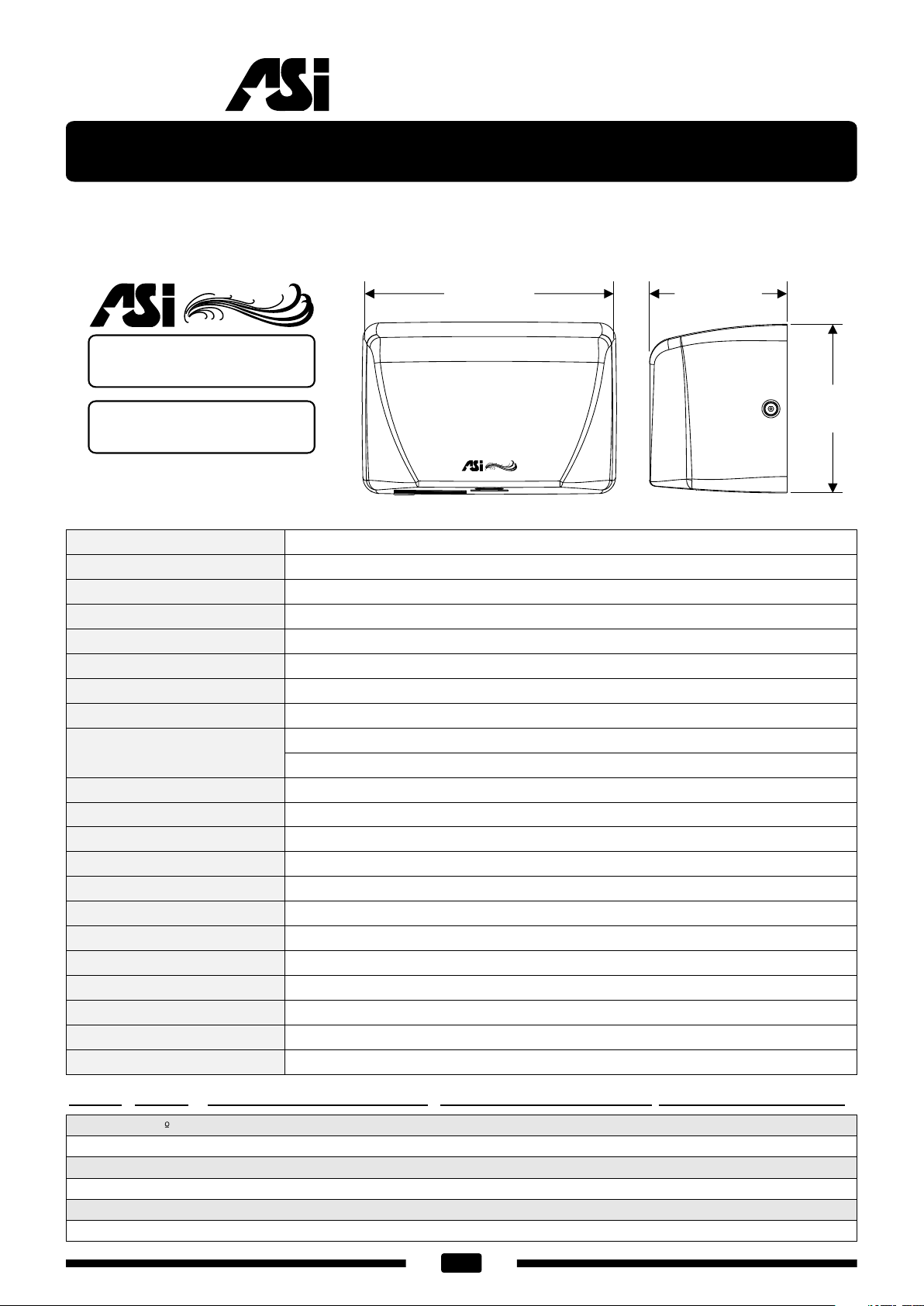
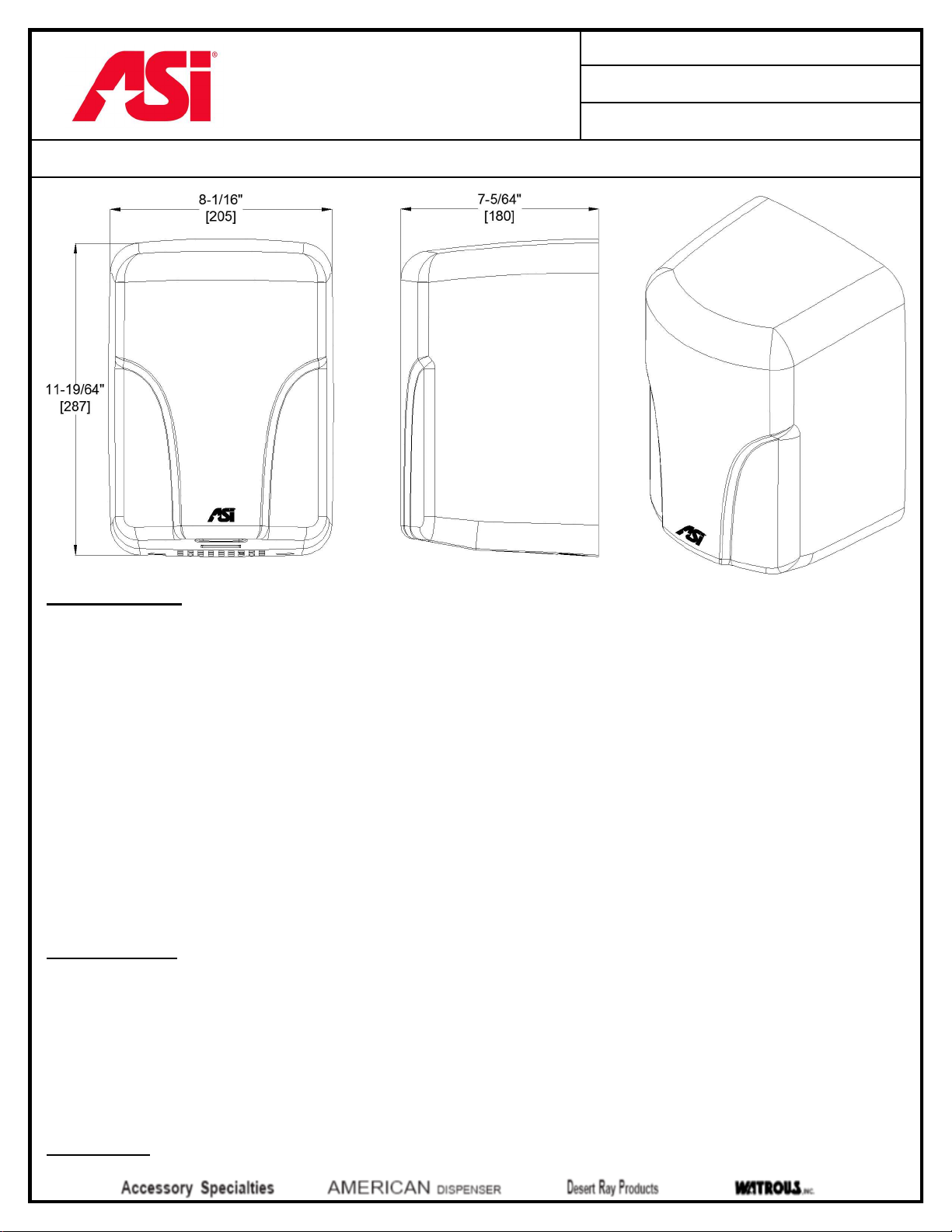
SURFACE MOUNTED HIGH-SPEED HAND DRYER (PAGE 1 OF 2)
MODEL : 0197
ISSUED: 2-08
REVISED: 16 AUG 2016
SPECIFICATION
Surface Mounted High-Speed Hand Dryer shall operate automatically from IR sensor activated by beam reflection from
objects placed in sensing zone. Motor and heating element shall have internal resetting automatic thermal protection. Unit
shall develop 68 CFM (116 m3/h) of heated air and shall provide drying time of less than 12 seconds. Warm air output
temperature and velocity shall be adjustable by owner. Cover shall be fabricated of heavy-duty, one piece formed stainless
steel 1/16" [1.5] thick finished on all exposed surfaces as satin or bright polished (by option specified) or heavy-duty, one
piece formed steel 1/16" [1.5] thick finished on all exposed surfaces with white porcelain enamel. Fixed directional air
nozzle shall be heavy-duty, rust proof and highly tamper resistant. Air intake slots shall not allow access to internal parts.
Circuitry shall have self-adjusting time-out and fail-safe off protection controlled by a microprocessor that shall detect and
reject false signals and shall automatically self-calibrate to provide uniform sensitivity over its entire life span. Sensitivity
shall be adjustable by owner to suit mounting conditions and intended usage population. Entire unit shall be internally
electrically grounded. Motor speed shall be adjustable by owner in range between maximum power and maximum
efficiency. Dryer unit shall have C-UL-US®, CE, and TÜV approval and be listed under the re-examination services of
Underwriters Laboratories, Inc. Unit shall be warranted against defects in materials or workmanship for five (5) years.
Surface Mounted High Speed Hand Dryer shall be Model 0197-___{specify voltage suffix}-____{specify color
option if other than white} of American Specialties, Inc., 441 Saw Mill River Road, Yonkers, NY 10701-4913
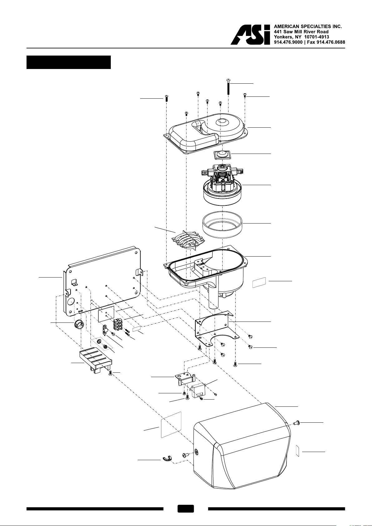
INSTALLATION
Surface mount unit on wall with four (4) 1/4" [6.4] washers and screws or bolts (not supplied) through holes (provided) in a
corrosion protected steel back plate into suitable prepared mountings (by others) or other suitable mounting hardware (by
others) to suit wall conditions. Electrical service is supplied and connected (by others) prior to installing cover. Cover is
secured to back plate with recessed, pin-hex socket head cap screws (supplied). For compliance with ICC/ANSI A-117.1-
2003 and 2010 ADA Accessibility Standards for adults, install unit with bottom of sensor lens 48" [1219] maximum above
finished floor (MAX AFF) if unobstructed reach access is provided or 44" [1118] MAX AFF if forward reach over an
obstruction (e.g. vanity or commode) with reach depth greater than 20" [508] and less than 25" [635] is only provided. For
general utility, install unit so that sensor lens is 44" to 54" [1118 to 1372] AFF.
OPERATION
Activate dryer by placing hands under sensor. Dryer automatically shuts off after user removes hands from sensor zone.

AMERICAN SPECIALTIES, INC.
441 Saw Mill River Road, Yonkers, NY 10701
(914) 476.9000 • (914) 476.0688
www.americanspecialties.com
THIS MANUFACTURER RESERVES THE RIGHT TO MAKE CHANGES IN DESIGN OR DIMENSIONS WITHOUT FORMAL NOTICE
SURFACE MOUNTED HIGH-SPEED HAND DRYER (PAGE 2 OF 2)
MODEL : 0197
ISSUED: 2-08
REVISED: 16 AUG 2016
COLOR OPTIONS*
Unit is supplied with white finish unless color option is specified. Specify optional covers Bright or Satin Stainless
Steel by adding appropriate code number suffix to standard model number.
COLOR
CODE
COVER COLOR
-92 Bright Stainless Steel
-93 Satin Stainless Steel
RATINGS
MODEL TYPE AIR
VELOCITY
TIMING
SAFETY
VOLTS AC
FREQUENCY Hz AMPS WATTS
x1000 COLOR
0197-1
Hand
156-224 mph
70-100 m/s Automatic
60 second
Shut-Off
110 V-120 V
50/60 Hz
14.6
Max 1.3-1.6
White*
0197-2156-224 mph
70-100 m/s
220 V-240 V
50/60 Hz
7.3
Max 1.3-1.6
MOTOR H/P RPM
x1000
FAN
TYPE HEATING ELEMENT CFM
m3/h
AIR OUTPUT
TEMPERATURE
Brush
Type
Dual Ball
Bearings
17-18 Multi-Inlet
Centrifugal
400-900 Watt Nichrome
wire with auto reset circuit
breaker
68
116
140o F ± 5 @ 77o F
(60o C ± 2.4 @ 25o C)
Ambient room temp
NET
WT
SHIP
WT
DRYING
TIME SENSING RANGE SAFETY WATER
PROTECTION
12.8
Lbs
5.8 kg
13.7 Lbs
6.2 kg
Less Than
12 seconds
5-1/8"-13-51/64" [130-
350] ADJUSTABLE
Standard = 7" ± 25/32"
[178 ± 20]
C-UL-US®,
CE, TÜV-GS
Drip Proof
IP23
SENSOR
TYPE
DRYING
PERSISTENCE
MOTOR THERMAL
PROTECTION
HEATER THERMAL
PROTECTION
SOUND
PRESSURE
IR
780 nm
Automatic
≤ 2 second Hold-
On Shut-Off delay
Shut off @ > 275 °F
{> 135 °C}
Reset on @ < 212 °F
{< 100 °C}
Shut off @ > 185 °F
{> 85 °C}
Reset on @ < 167 °F
{< 75 °C}
71.1-74.4 dB-A
@ 1m
65.4-69 dB-A
@ 2m
This manual suits for next models
1
Other ASI Dryer manuals
Popular Dryer manuals by other brands

Gardner Denver
Gardner Denver RDS Series Operation and maintenance

Dexter Laundry
Dexter Laundry T-20SWD Installation & operation instructions

GE
GE GTD42GASJ0WW Installation instruction

Kenmore
Kenmore Super capacity plus clothes dryer 64912 user guide

Electrolux Professional
Electrolux Professional TD6-20 N2 Series user manual

Kenmore
Kenmore 62842 owner's manual

B-Air
B-Air Bear Power Pro Series Instrucion manual

ASI JD MACDONALD
ASI JD MACDONALD 10-20200-2 Operating instructions and parts manual

Toto
Toto TYC602P user manual

Ryonet
Ryonet RCJ21-3500 manual

Hotpoint
Hotpoint TVAM 70 Aquarius Insrtuction booklet

Hotpoint Ariston
Hotpoint Ariston TCD 87B Instruction booklet