AMERICAN SPECIALTIES, INC.
441 Saw Mill River Road, Yonkers, NY 10701
(914) 476.9000 • (914) 476.0688
www.americanspecialties.com
THIS MANUFACTURER RESERVES THE RIGHT TO MAKE CHANGES IN DESIGN OR DIMENSIONS WITHOUT FORMAL NOTICE
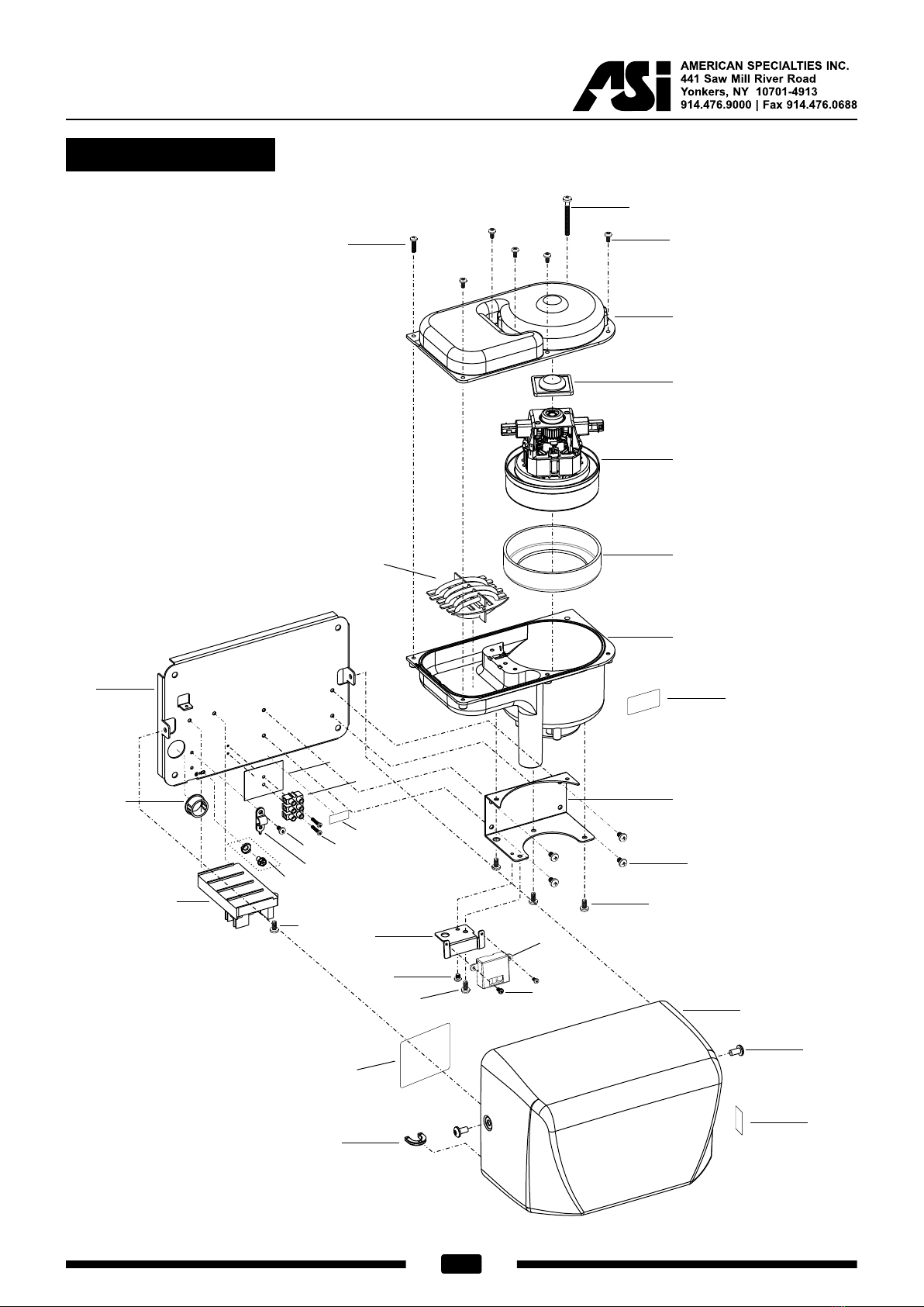
SAFE-Dri™ - HIGH SPEED ANTI-LIGATURE HAND DRYER (PAGE 2 OF 2)
MODEL : 0198-MH
ISSUED: 6/2015
REVISED: 22 Feb 2016
INSTALLATION
Mount unit cabinet in wall recess with four (4) 10 [M5] screws (not supplied) into suitably prepared mountings
(by others) or other suitable mounting hardware (by others) to suit wall conditions. For masonry walls use
expansion bolts or anchors for 1/4" [M6] screws. See unit diagram for electrical service cable rough-in location.
Electric service of 100-240VAC 20A 50/60 Hz (provided by others) is brought to RWO at location for dryer
indicated on diagram above and is hooked up (by others) in accordance with schematic and Owner’s Manual
provided with unit. Electrical service is supplied and connected (by others) prior to installing cover. Cover is
secured to cabinet with four (4) pin-hex socket flat head security screws (supplied). For compliance with ICC/
ANSI A-117.1 and 2010 ADA Accessibility Standards install unit with top of dryer hand chamber 48" [1219]
maximum above finished floor (MAX AFF) if clear floor reach access is provided or 46" [1168] MAX AFF if side
reach access over an obstruction (e.g. vanity) with reach depth greater than 10" [254] and less than 25" [635] is
only provided or 44" [1118] MAX AFF if forward reach over an obstruction (e.g. commode) with reach depth
greater than 20" [508] and less than 25" [635] is only provided. For general utility install unit so that top of dryer
hand chamber is 44" to 50" [1118 to 1270] AFF. Note that top of RWO is 9/32" [7] below top of unit. For
installation of two or more dryers, dryers should be no closer than 24" [610] on center. See OM and Template MT
& IG supplied with unit.
RWO required is 12-1/4" W x 15-3/16" H x 5-1/4" D minimum [311 x 386 x 133]
OPERATION
User activates dryer by placing hands under sensor. Dryer automatically shuts off after time-out when user
removes hands from sensor zone.
MODEL TYPE TIMING SUPPLY
AC VOLTS HERTZ (HZ)
AMPS
(MAX)
WATTS
X1000 COVER
0198-MH-1
Hand Automatic
115-120 50/60 10.4 0.84-1.0 Satin Finish;
Vertical Grain;
304 Stainless Steel
0198-MH-2208-240 50/60 5.2 0.84-1.0
MOTOR H/P RPM FAN TYPE AIR FLOW HEATING ELEMENT HEAT TEMP.
Brush Type
Dual Ball
Bearings
0.67 29 Multi-Inlet
Centrifugal
60 CFM
[102 m3 /h]
230 ft/s
[70 m/s]
500 Watt with auto reset
circuit breaker
131º F ± 5 @ 77º F
[55º C ± 2.8 @ 25ºC]
Ambient room temperature