ASIX Forte User manual
FORTE
Reference Manual
High-Speed USB Programmer

ASIX s.r.o.
Staropramenna 4
150 00 Prague
Czech Republic
www.asix.net
support@asix.net
sales@asix.net
ASIX s.r.o. reserves the right to make changes to this document, the
latest version of which can be found on the Internet.
ASIX s.r.o. renounces responsibility for any damage caused by the use
of ASIX s.r.o. products.
© Copyright by ASIX s.r.o.

Table of Contents
Introduction 9
1
9
1.1 Abbreviations & Terms Used
FORTE 10
2
10
2.1 Package Content
10
2.2 Features
11
2.3 Quick Start
11Windows2.3.1
11Linux2.3.2
11
2.4 Use
13
2.5 Controls and Connectors
13Programming Connector2.5.1
14GO Button2.5.2
14LED Indicators2.5.3
ACTIVE 14
ON-LINE 14
14USB Connector2.5.4
14
2.6 Connecting to Application
14Custom-made Connecting Cable2.6.1
15Programming in ZIF Socket2.6.2
15Connecting Procedure2.6.3
Table of Connections 16
17Connection Examples2.6.4
PIC Microcontrollers 17
AVR Microcontrollers 17
AVR with TPI Interface (e.g. ATtiny10) 18
ATxmega with PDI Interface 18
Atmel 8051 18
Cypress PSoC 19
MSP430 / CC430 with TEST Pin, JTAG Interface 19
MSP430 / CC430 without TEST Pin, JTAG Interface 20
MSP430 / CC430, SBW Interface 20
TI (Chipcon) CCxxxx 21
STM8 21
ARM with SWD interface 21
I2C Memory Chips 21
SPI Memory Chips 22
Microwire Memory Chips 22
UNI/O Memory Chips 22
1-Wire Interface 23
JTAG Interface 23
24
2.7 HPRAVR Adapter
24Use2.7.1
25
2.8 Technical Specifications
25Limit Values2.8.1
25Operating Specifications2.8.2
27Declaration of Conformity2.8.3
DRIVERS 28
3
28
3.1 Driver Installation
28Windows Operating Systems3.1.1
Windows 7 and later 28
Older supported Windows versions 28
29Linux3.1.2
29
3.2 Driver Updating

UP SOFTWARE 30
4
30
4.1 Abbreviations Used
30
4.2 Installation
30
4.3 Device Programming
30Programmer Selection4.3.1
31Projects4.3.2
31Device Type Selection4.3.3
31Program settings4.3.4
Longer delay for VDD switching on/off when
supplied from programmer 32
Production Programming Settings 33
Settings for Programming During Development 33
Programmer Settings 33
Fuses and Working with Them 34
34Programming4.3.5
Differential Programming 35
35
4.4 Further Features
35Setting the GO Button4.4.1
35Mass Production4.4.2
36Serial Numbers4.4.3
Format of Files with Serial Numbers 37
Data Record 37
Example of File with Serial Numbers 38
38Calibration Memory Support4.4.4
Working with Calibration Memory When Erasing a
Device in UV Eraser 38
Working With Calibration Memory in Devices With
Flash Memory 39
39
4.5 Program Controls
39Toolbar4.5.1
39Status Bar4.5.2
39Menus4.5.3
File Menu 40
File ➙ New 40
File ➙ Open... 40
File ➙ Open next file... 40
File ➙ Reload actual file 40
File ➙ Save 40
File ➙ Save as... 40
File ➙ Import data memory from file... 40
File ➙ Open file with data memory automatically 41
File ➙ New project 41
File ➙ Open project... 41
File ➙ Save project... 41
File ➙ Close project 41
File ➙ Recent projects 41
File ➙ Read calibration data... 41
File ➙ Save calibration data... 41
File ➙ Export to bin... 41
File ➙ Exit 42
Edit Menu 42
Edit ➙ Fill with value... 42
Edit ➙ Text insert... 42
Edit ➙ Fill selected location with RETLW 42
View Menu 42
View ➙ Code/main memory 42
View ➙ Data memory 43
View ➙ Configuration memory 43
View ➙ Display code/main memory 43
View ➙ Display data memory 43
View ➙ Display configuration memory 43
Device Menu 43
Device ➙ Program 43
▸ Program all 43
▸ Program all except data memory 43
▸ Program code/main memory 44
▸ Program data memory 44

▸ Program configuration memory 44
▸ Program differentially 44
▸ Differential program data memory 44
▸ Mass Production 44
Device ➙ Read 44
▸ Read all 44
▸ Read all except data memory 44
▸ Read code/main memory 45
▸ Read data memory 45
▸ Read configuration memory 45
Device ➙ Verify 45
▸ Verify all 45
▸ Verify all except data memory 45
▸ Verify code/main memory 45
▸ Verify data memory 45
▸ Verify configuration memory 45
Device ➙ Erase 45
▸ Erase all 45
▸ Erase code/main memory 46
▸ Erase data memory 46
Device ➙ Blank check 46
▸ Blank check all 46
▸ Blank check all except data memory 46
▸ Blank check of code/main memory 46
▸ Blank check of data memory 46
▸ Blank check of configuration memory 46
Device ➙ Select device 46
Options Menu 47
Options ➙ Program settings ➙ Programming 47
▸ Reload file before every programming 47
▸ Ask before erasing 47
▸ Ask before programming of OTP / Flash /
Code/Data Protection / differential 47
▸ Display fuse warning messages 47
▸ Except for programming: Close status
window 47
▸ After programming: Close status window 47
▸ Beep after successful finishing 47
▸ Beep after unsuccessful finishing 47
▸ Turn off all sound for UP 48
▸ Slower switching of voltage with ICSP 48
▸ Do not perform blank check before cfg
word programming 48
▸ Do not perform blank check after erasing 48
▸ Do not erase device before programming 48
▸ Do not erase data memory before its
programming 48
▸ Do not verify unprogrammed words at the
end of the memory 48
▸ Do not verify 48
▸ Verify with two supply voltages 49
Options ➙ Program settings ➙ Panels 49
▸ Display selected device on toolbar 49
▸ Display selected programmer on toolbar 49
▸ Display the status bar in the lower part of
the window 49
▸ Display icons on toolbar buttons 49
▸ Display descriptions on toolbar buttons 49
▸ Show mass production counter in status
bar 49
Options ➙ Program settings ➙ Files 49
▸ File save style 49
▸ Automatically check for newer versions of
actual file 50
▸ Check device type when loading .hex file 50
▸ Save device type into .hex file 50
▸ Warn when loaded file does not contain
CFG memory data 50
▸ Binary file loading and saving style 50
▸ Save unused locations to .hex file 50
▸ Clear code/main / data memory / ID
positions before file reading 50
▸ Erase configuration memory before file
reading 50
▸ Read data memory not from the file but
from the device 51
▸ Read ID positions not from the file but
from the device 51

▸ Project saving style 51
Options ➙ Program settings ➙ Colors 51
Options ➙ Program settings ➙ Editors 51
▸ Code/main memory editor: show words as
bytes 51
▸ Code/main memory editor 8 words wide 51
▸ Data memory editor 8 words wide 51
▸ Boot memory editor 8 words wide 51
▸ Show only the lowest byte of word in ASCII 52
▸ Mask ID positions while reading from
device, from file, etc. 52
▸ Mask ID positions during direct user input 52
▸ Configuration memory editor: show cfg
word instead of fuses 52
Options ➙ Program settings ➙ Serial numbers 52
▸ Serial numbers 52
▸ Prepare S/N before programming 52
▸ Find successor after programming 52
▸ Prepare S/N after programming 52
▸ Serial number interval 52
▸ Log to file 52
▸ Serial number length (the number of
characters) 52
▸ Number base 53
▸ Code as ASCII 53
▸ Initial serial number 53
▸ Next S/N 53
▸ Destination 53
▸ Hexadecimal address of first word 53
▸ Fill with RETLW instruction 53
▸ Characters per word 53
▸ Sequence 53
Options ➙ Program settings ➙ Others 53
▸ Update check settings 53
▸ Allow internal and external supply
voltages collision 53
▸ Do not show warning if internal 5V is
switched on with 3.3V device 54
▸ Allow to change supply voltage level when
it is on 54
Options ➙ Select programmer 54
Options ➙ Language selection... 54
Options ➙ Keyboard shortcuts... 54
Help Menu 54
Help ➙ Help on program 54
Help ➙ List of supported devices 55
Help ➙ Check Internet for updates 55
Help ➙ ASIX website 55
Help ➙ About 55
55Programmer Settings Window4.5.4
FORTE Programmer Settings Window 55
Power supply from the programmer 55
In idle state 55
During programming 55
Reset 55
Settings Associated with PIC Microcontrollers 55
▸ Programming method 55
▸ Use PE 55
Settings Associated with AVR Microcontrollers 55
Oscillator frequency 56
Faster Programming with Slow Clock 56
Inverse Reset 56
HVP 56
Settings Associated with I2C Memory Chips 56
I2C Bus Speed 56
I2C Memory Address 56
PRESTO Programmer Settings Window 56
Idle Power Supply 56
Active Power Supply 56
Settings Associated with PIC Microcontrollers 56
MCLR Pin Control 56
Programming Method 57
Algorithm Programming 57
Use PE 57
Settings Associated with AVR Microcontrollers 57

Oscillator Frequency 57
Faster Programming with Slow Clock 57
Inverse Reset 57
HVP 57
Settings Associated with I2C Memory Chips 57
I2C Bus Speed 57
I2C Memory Address 57
57HEX Editor Windows4.5.5
Selecting an Area 58
Code/Main Memory Editor 58
Data Memory (EEPROM) Editor 58
Configuration Memory Editor 58
Tips for Advanced Users 58
59
4.6 Running UP from Command Line
59List of Parameters4.6.1
Using a Project File 60
Examples of Use 60
File Opening 60
Device Programming 61
61Program Return Codes4.6.2
61
4.7 Running UP by Means of Windows
Messages
62List of Commands4.7.1
Example of use 63
64
4.8 UP_DLL.DLL Library
65
4.9 Running More Than One Instance of UP
65
4.10 Access of More UP Instances to One
Programmer
65
4.11 Updating UP
66
4.12 Appendix A UP_DLL.DLL
66Data Types4.12.1
66List of UP variables4.12.2
70
4.13 Appendix B: Use of ICSP
70Pins Used for Programming4.13.1
HVP Algorithm 70
LVP algorithm (without VPP) 70
Loading of Different Programmer Pins 70
71Power Supply Options4.13.2
Power Supply Capacities in Application 71
72ICSP Connector4.13.3
72
4.14 Appendix C: Intel‑HEX File Format
72Supported Alternatives of HEX Files4.14.1
73Description of Intel‑HEX File Format4.14.2
Data Record 73
End of File 73
Extended Linear Address 73
Saving Device Type in .hex File 74
JTAG PLAYER 75
5
75
5.1 JTAG Device Programming
75SVF File5.1.1
Examples of How to Create SVF Files 75
State of .svf File Implementation 76
76XSVF File5.1.2
Examples of How to Create XSVF Files 76
State of XSVF File Implementation 77
77Programming Connector5.1.3
77
5.2 Settings
77Default TCK signal frequency5.2.1
78Fast Clocks Option (FORTE only)5.2.2
78RUNTEST without run_count (SVF only)5.2.3
78RUNTEST Timing Multiply (both SVF and XSVF)5.2.4

78RUNTEST with run_count and no timing
(bothSVFandXSVF)
5.2.5
79VPP PRESTO / P FORTE pin usage while running test
(file) / after test completion
5.2.6
79Default Settings5.2.7
Default Settings for FPGAs 79
Default Settings for XC9500 79
Default Settings for AVR: 79
80
5.3 Running JTAG Player from Command Line
TROUBLE-SHOOTING 81
6
81
6.1 Tips and Tricks
81
6.2 FORTE Tester
Document history 83
7

Page 9
1
Introduction
This manual describes FORTE, a High-Speed USB
programmer and its control software, both manufactured
by ASIX.
Chapter 1 gives you ‘quick start’ instructions on how to
start working with the programmer, offers examples of its
connecting to applications and provides technical
specifications.
Chapter 2 focuses on the installation of drivers and
software updates.
Chapter 3 introduces the UP program, which is software
used for controlling all ASIX programmers. You can find
procedures there for setting up the programmer prior to
programming, for actual programming and/or verification
of devices. It also describes how to control the software
from a command line or a DLL library.
Chapter 4 presents the JTAG SVF Player software used for
programming devices with the JTAG interface using .svf/
.xsvf files.
Chapter 5 offers tips and tricks in case of experiencing
difficulties with programming.
1.1 Abbreviations & Terms
Used
HVP (High Voltage Programming) is a
programming mode in which a higher
voltage than the power-supply voltage is
applied to pin P in the initial phase.
ICSP (In-Circuit Serial Programming). The
meaning of ICSP is identical with the
meaning of ISP (In System Programming) in
this manual, i.e. device programming done
inside a system.
LVP (Low Voltage Programming) is a
programming mode in which none of the
pins has higher than the power-supply
voltage applied.
PDI Program and Debug Interface
SBW (SPY-BI-WIRE) MSP430 microcontroller
interface
SWD (Serial Wire Debug) ARM microcontroller
interface
TPI Atmel Tiny Programming Interface
VCC If the text features VCC or VDD, they mean
the power-supply voltage on the VDD pin,
which can serve as either input or output
depending on the particular application.
VPP If the text features VPP, it means the
programming voltage on pin P of devices
with High Voltage Programming.
The term “file” means a file with data to be programmed
in context of this manual, in other cases a particular type
of file is specified. A file with .hex extension means Intel-
HEX file whilst a file with .bin extension means binary file.

Page 10
2
FORTE
Thank you for buying the FORTE programmer made by
ASIXs.r.o. It was a wise decision. Feel free to contact our
technical support in case of any questions or doubts.
2.1 Package Content
Your Forte package should include:
FORTE programmer
ICSPCAB16 cable
ICSPCAB8 cable
USB cable (type A - B)
CD-ROM with manual and drivers
Info leaflet
2.2 Features
FORTE is a fast and flexible High-Speed USB In-System
programmer suitable for programming a range of devices
such as microcontrollers, EEPROM or Flash serial memory
chips, CPLD, FPGA and many others.
very fast programmer (30MHz out, 15MHz in/out)
High-Speed USB2.0 (480Mbps) interface, programmer
powered via USB
embedded processor pro comprehensive functions
synchronous and asynchronous programming, JTAG
support
programming voltage from 1.8V 1 to 5.5V
feeds applications with 1.8V to 5.5V
programming interface of 8×I/O + individually
configurable pull-up/down resistors
built-in fast input/output HW protection, independent of
the status of the PC
overcurrent protection on VDD and P sources
overvoltage protection on VDD pin
GO button for quick function selection
more than one simultaneously running programmer per
PC, command line support, support for Windows
messages and for DLL
Windows XP or later, Linux (Wine)
compact
1 lower speeds can typically be programmed at less than
1.2V.

Page 11
2.3 Quick Start
Please install the drivers and the UP software prior to the
first use of FORTE.
2.3.1 Windows
Administrator rights are required to run the software
for the first time.
Start with installing the UP program. Its installer installs
the USB driver for FORTE, too. You can find the installer
on the supplied CD-ROM or on the web (the preferred
option).
Once the installation is complete, connect the FORTE
programmer to your computer. In Windows XP it is
necessary to confirm the installation in “Found New
Hardware” wizard. The green ON-LINE LED should turn on
after a few moments and the Windows Device Manager
should present the programmer as correctly installed.
2.3.2 Linux
The programmer can be operated under Wine in Linux.
Please find detailed installation instructions at:
http://www.asix.net/tools/supp_linux.htm.
2.4 Use
FORTE is a fast and flexible High-Speed USB programmer
suitable for programming of a range of devices such as
microcontrollers, EEPROM or Flash serial memory chips,
CPLD, FPGA and many others. It is equipped with
overcurrent protection at the VDD and VPP sources and
with overvoltage protection at the VDD pin.
The programmer is powered via USB. It can feed the
application to be programmed with a voltage of 1.8V to
5.5V or it can utilize an external application’s voltage
during programming.
The programmer may run under Windows XP or later or
under Linux in Wine.
Numerous Supported Devices
The list of supported devices includes:
Microchip PIC microcontrollers – devices with serial
programming, which include all PIC and dsPIC devices
with the exception of several obsolete types.
Microcontrollers with ARM core – such as ATSAM3N2A
or LPC2148.
Atmel AVR microcontrollers – all devices supporting
"SPI Low Voltage Serial Downloading" such as ATtiny12,
AT90S8535 or ATmega128.
Atmel ATxmega microcontrollers – devices
programmable via JTAG or PDI interface such as
ATxmega32D4 or ATxmega128B1.
Atmel AVR32 microcontrollers – AT32UC3A1256, for
example.
Atmel 8051 microcontrollers – devices that support ISP
programming such as AT89S8253, AT89LP4052,
AT89LP216 or AT89S2051.
Texas Instruments microcontrollers – 16-bit MSP430,
CC430 and CCxxxx with a flash memory, including their
fuse programming.
Cypress – PSoC microcontrollers.
Serial EEPROM and Flash memory chips - I2C
(24LCxx), Microwire (93LCxx) and SPI (25Cxx).
Devices with JTAG interface, for which an SVF or an
XSVF file can be created. These include CPLD (such as
Xilinx XC95xx and CoolRunner), configuration memory
for FPGA (such as Xilinx XC18Vxx and XCFxxS),
microcontrollers (such as ATmega128) and others.
This, however, is not an exhausting list of possibilities.
Additional types are regularly supplemented in response
to customers’ interest. New software versions are
downloadable from the Internet for free.

Page 12
High Speed
Compared to the PRESTO programmer, FORTE features an
embedded processor making it possible to perform
complex operations with the device being programmed as
well as offering a significantly faster output interface. Due
to this, devices may be programmed up to the limits of
their theoretical performance.
USB Connection
FORTE is controlled and powered through a USB port. It
communicates in the High-Speed mode (480Mbps) /
connected to a USB 2.0 port and in the Full-Speed mode /
connected to a USB 1.1 port. This means that connecting
the programmer is fast and easy, requiring only a single
cable.
Programming of Placed Devices
ISP (In-System Programming) or the special ICSP (In-
Circuit Serial Programming) for the PIC microcontrollers is
currently replacing the traditional method in which
devices were first programmed and only then placed on a
PCB (printed circuit board). Thanks to ISP even SMD
devices with an extremely narrowly spaced pins can
easily be programmed and their firmware upgraded in
already assembled and finished devices.
Programming of Autonomous Devices
Those who still need to program autonomous devices, i.e.
devices not yet placed on a PCB can use the ISP2ZIF
adapter featuring a ZIF (zero insertion force) socket.
Programming Interface
The FORTE programmer features 8 independent I/O pins
with individually configurable pull-up/down resistors.
Devices to be programmed are connected through a
16-pin ISP connector, which is backward compatible with
the 8-pin ICSP connector for PIC microcontrollers. VPP can
be set to any value between 6.5 V and 17 V.
Connection to a remote application through a 16-wire
ribbon cable has been improved by interleaving its
individual signals with ground.
Power Supply From Application
The VDD output can serve as an input using the power
from the application for feeding the output buffers, or it
can become an output and as such to provide voltage for
the application.
FORTE can power applications with a voltage from 1.8V
to 5.5V. A controlled discharge resistor is incorporated
for faster transitions between different programming
phases when capacitors in the application need to be
discharged all the way down to 0V.
FORTE includes a built-in “voltmeter” at pins P and VDD.
Overcurrent Protection
FORTE includes a fast-responding hardware overcurrent
protection at pins P and VDD, which is independent of the
state of the controlling PC.
User Interface
The programmer status is clearly indicated by two LEDs.
ON-LINE (green LED) informs of connecting to USB while
ACTIVE (two-state yellow/red LED) signals an activity or a
faulty state (error) of the programming interface.
The GO button significantly increases the operator’s
comfort in repeated programming. It starts programming
or other user-defined commands
Software
The UP program is a basic software tool for working with
FORTE, also compatible with the PRESTO programmer.
Apart from standard commands, UP provides numerous
above-standard functions, which broaden the
programmer’s applications and simplify its operation.
These include the possibility to define projects, existence
of adjustable parameters when running from the

Page 13
command line providing for unattended programmer
operation in routine programming, environment
personalization incl. keyboard shortcuts, automatic
generation of serial numbers, etc.
UP has been developed for Windows XP or later. It also
works under Linux (through Wine).
Modified drivers developed by FTDI are used for
communication through USB.
Devices with the JTAG interface, for which an SVF or an
XSVF file can be created, can be programmed by means
of the JTAG SVF Player software.
The voltage at the VDD pin is permanently displayed in
UP for greater comfort and for monitoring of the
operation. The reset signal is conveniently controlled by a
single button.
2.5 Controls and
Connectors
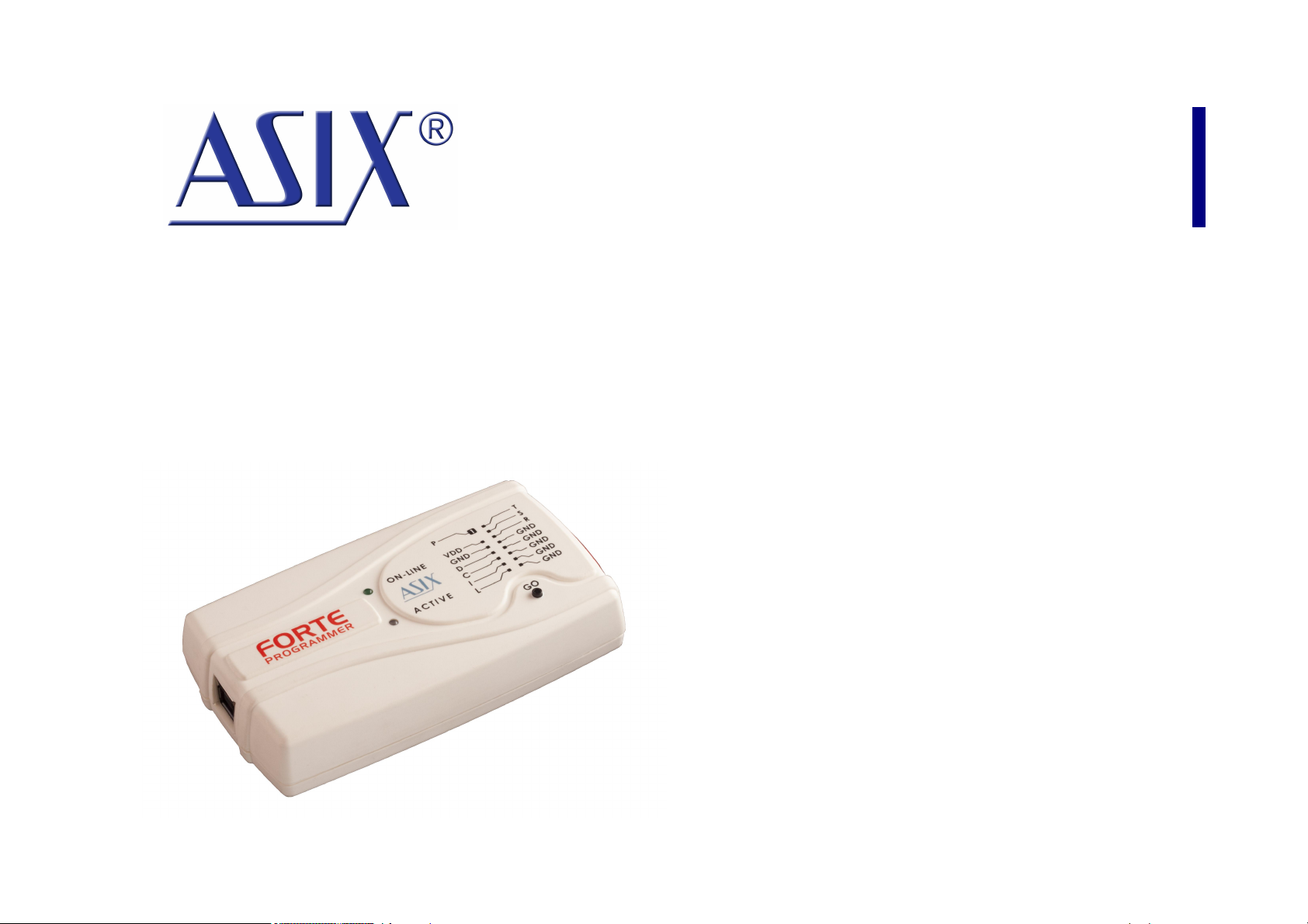
Fig.2: The FORTE programmer
FORTE features two LEDs, a button, a connector for
linking to USB and a programming connector.
2.5.1 Programming
Connector
The programming connector is a 16 way double row plug
with pin No. 3 (in standard numbering) missing. Spacing
between pins is 2.54mm.
Fig.3: Programming connector
Pin
Type
Description
P
I/O, VPP
signal input/output or VPP output
VDD
PWR
power input/output
GND
PWR
signal grounding
D, C, I, L, T, S, R
I/O
signal input/output
Table 1: programming connector
Page 14
2.5.2 GO Button
This button simplifies work with the application being
programmed. It triggers device programming or another
pre-programmed function. For further information on
settings see Setting the GO Button.
2.5.3 LED Indicators
ACTIVE
This two-state LED informs you of the equipment status.
The yellow color means that there is ongoing
communication between the programmer and a device.
A red color signals an error state.
ON-LINE
The green LED informs you that FORTE is connected to a
computer and that the computer and the programmer
“understand each other”, i.e. drivers are installed and
work correctly.
In Linux, the green LED turns on upon connecting the
programmer to a PC even before the driver is correctly
installed.
2.5.4 USB Connector
A standard USB (type B) connector is provided for
connecting to a computer. The programmer uses the
USBHigh-Speed (480 Mbps) interface for communication.
2.6 Connecting to
Application
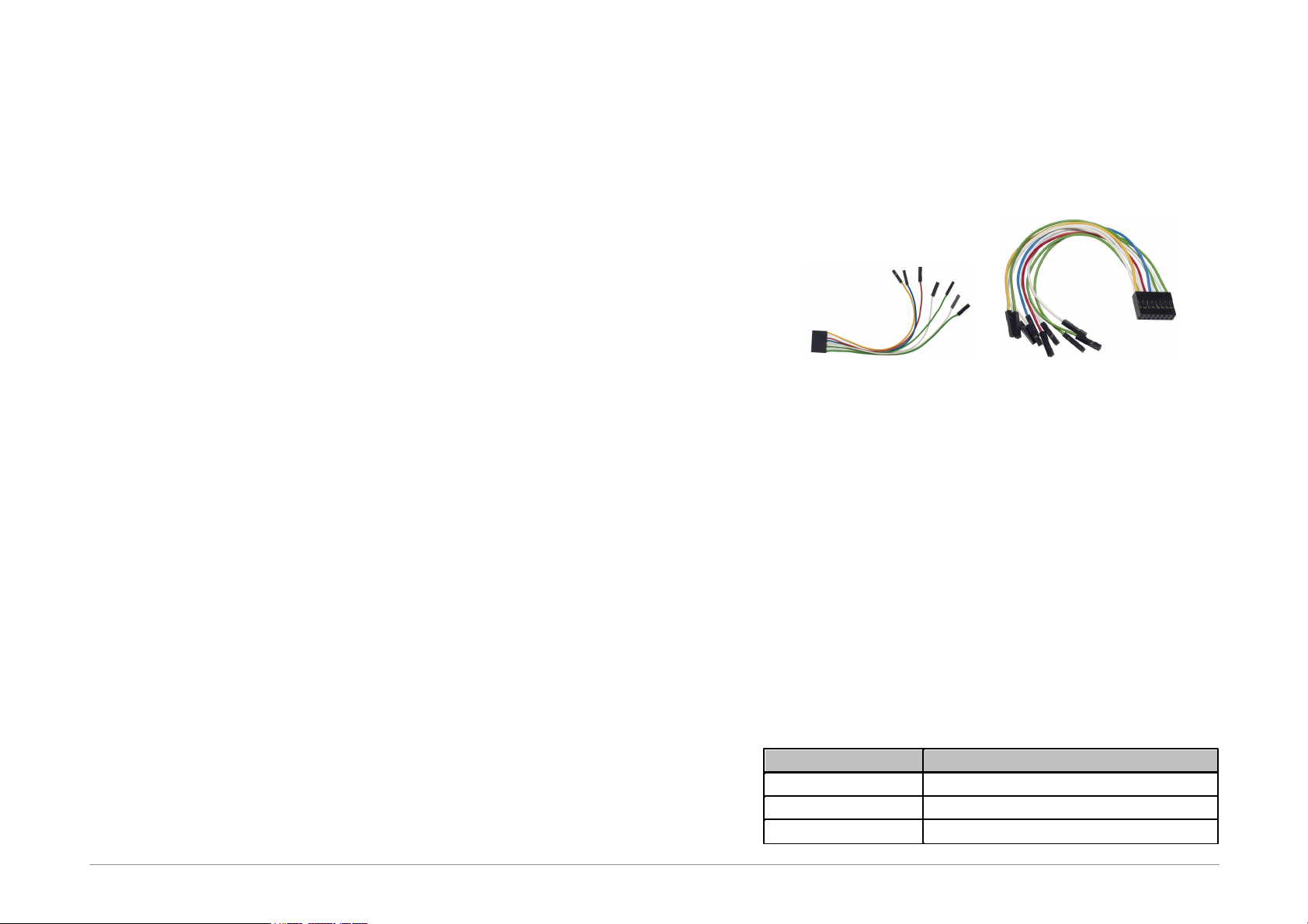
The programmer should be connected to an application to
be programmed with an ICSPCAB8 or ICSBCAB16 cable.
The cables are designed for 2.54 spacing.
Fig.4: ICSPCAB8
Fig.5: ICSPCAB16
2.6.1 Custom-made
Connecting Cable
Should an application to be programmed have a non-
compatible type of connector for linking to the
programmer, the customer can make his/her own
programming cable. Its length should not exceed 15cm.
This is where interleaving of individual signals with GND
in a 16-wire ribbon cable can be used conveniently. In
order to utilize this ground-interleaving, all GND signals
must be actively connected on the application's side.
The following table lists markings of connectors by FCI
Electronics suitable for making a custom cable. Ofcourse,
it is possible to use any similar ones:
FCI marking
Description
65039-036LF
housing, 1 pin
65039-029LF
housing, 1 x 8 pins
65043-029LF
housing, 2 x 8 pins

Page 15
47217-000LF
pin
Table 2: ICSP cable - material list
A cable with a cross-section between 0.1 and 0.3 mm2
may be used for making the custom connecting cable.
2.6.2 Programming in ZIF
Socket
If programming of autonomous device is required, i.e.
those that are only later connected to an application, it is
possible by means of our optional ISP2ZIF accessory.
Fig.6: ISP2ZIF
ISP2ZIF consists of a zero insertion force (=ZIF) socket
and an ICSP connector for connecting to the programmer,
which can also provide voltage for feeding the program
circuitry.
2.6.3 Connecting
Procedure
The correct procedure for connecting the programmer:
first connect FORTE to the target application, then
connect FORTE to the USB and finally turn on the
application’s power supply.
Please make sure that the GND of the application, the
programmer and the USB are interconnected before
signals and the power are applied.
Important warning
If an application is powered by a switched
power source or is not grounded, a significant
voltage difference may appear between the
programmer’s ground and the application’s
ground. This could damage the programmer.
The simplest way of connecting the GND prior to the
other signals is to ground the application before
connecting it to the programmer. This can, for example,
be achieved by making the GND pin of the application’s
ICSP connector longer than the other pins. It will make
sure that both grounds are interconnected first.
Page 16
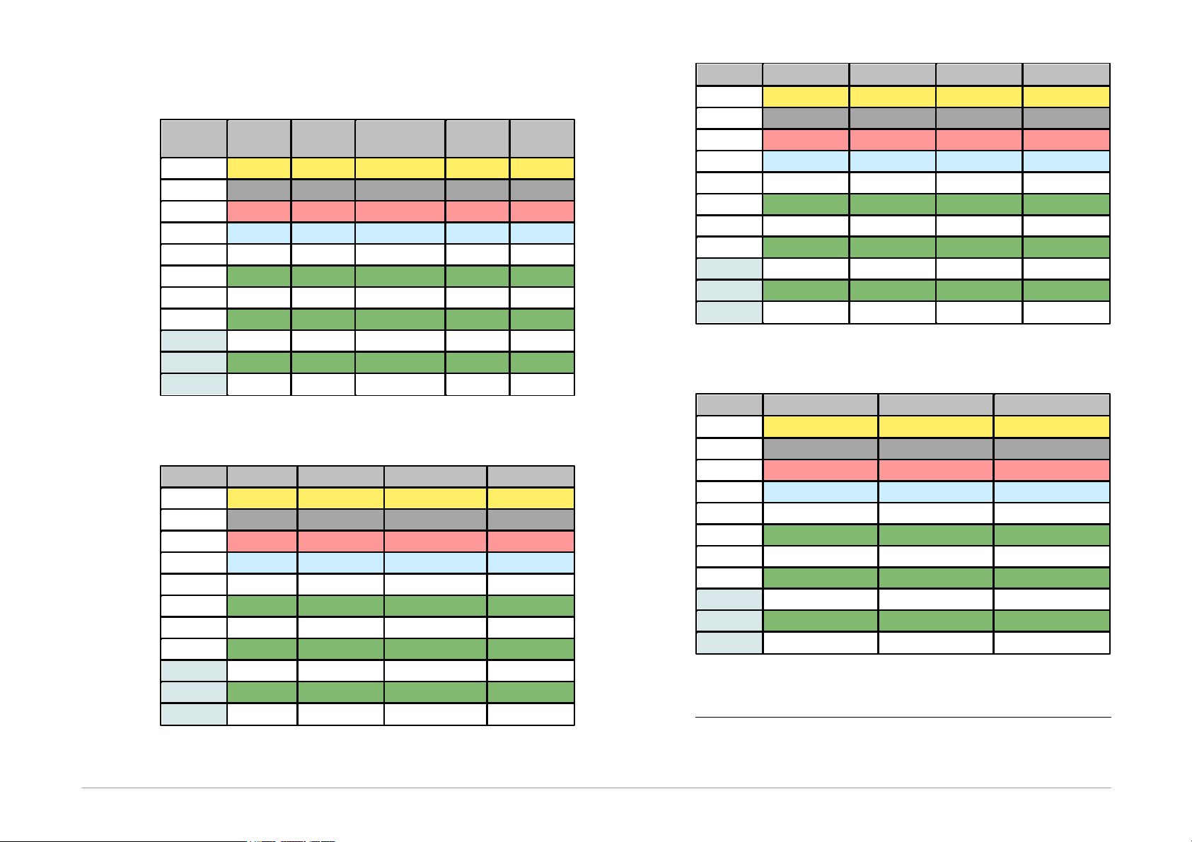
Table of Connections
Pin
AVR
AVR TPI
ATxmega
PDI
8051
JTAG
P
RESET
RESET
RESET
USR
-
VDD
VCC
VCC
VCC
VCC
VDD
GND
GND
GND
GND
GND
GND
D
MOSI
TPIDATA
PDI_DATA
MOSI
TDI
C
SCK
TPICLK
PDI_CLK
SCK
TCK
I
MISO
MISO
TDO
L
SS
TMS
T
S
R
Table 3: Connection list No.1
Pin
PIC
MSP430
MSP430 SBW
TI CCxxxx
P
MCLR
TEST/VPP
VPP
RESET
-
VDD
VDD
VCC
VCC
VDD
GND
VSS
VSS
VSS
GND
D
PGD
TDI
SBWTDIO
Debug_data
C
PGC
TCK
SBWTCK
Debug_clock
I
TDO
L
LVP
TMS
T
S
R
RESET
Table 4: Connection list No.2
Pin
I
2
C
SPI
Microwire
UNI/O
P
- CS
CS
-
VDD
VDD
VDD
VDD
VCC
GND
GND
GND
GND
VSS
D
SDA
SI
DI
SCIO
C
SCL
SCK
CLK
I
SO
DO
L
ORG/(PRE)
T
S
R
Table 5: Connection list No.3
Pin
PSoC
1-Wire
ARM SWD
P
XRST
IO1
NRST
-
VDD
VDD
VDD
VDD
GND
VSS
GND
GND
D
ISSP-DATA
SWDIO
C
ISSP-SCLK
SWCLK
I
L
T
S
R
Table 6: Connection list No.4
1 An external pull-up resistor or possibly a Schottky diode
should be connected for 1-Wire components – see
chapter 1-Wire Interface.

Page 17
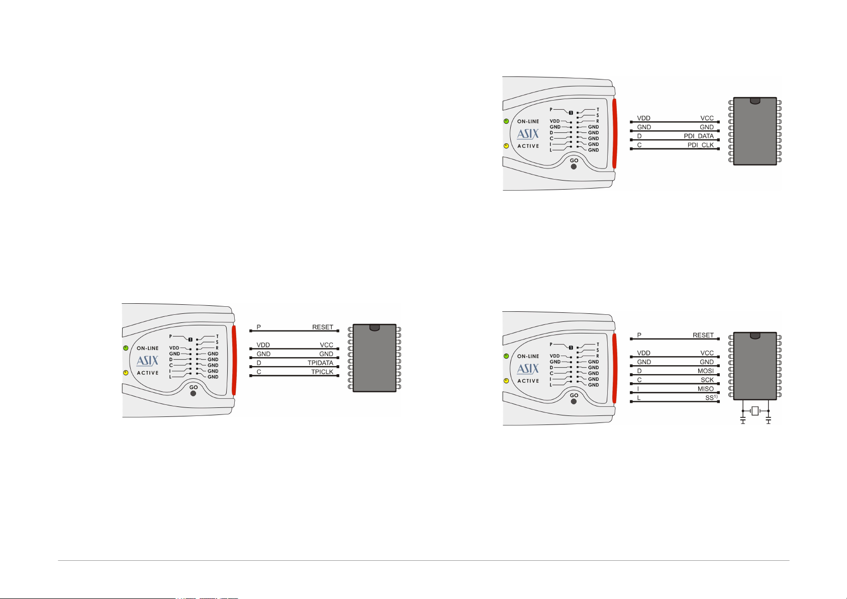
2.6.4 Connection Examples
The following text presents examples of connections
between FORTE and the device being programmed. We
use a notation according to the manufacturer datasheet
of each particular device.
PIC Microcontrollers
Fig.7: PIC microcontroller
1)Not all devices have the PGM pin. The PGM pin can be
connected to programmer’s L pin, to VSS via a pull-
down resistor (for HVP programming) or to VDD via a
pull-up resistor (for LVP programming).
2)The whole device must be erased before programming
if code/main memory protection (CP) or data memory
protection (CPD) is active.
3)Some devices cannot be erased when CP or CPD is
active if the power-supply voltage is less than 5V.
4)If a microcontroller has more than one power-supply
VDD or VSS pin, all of them must be connected
including the AVDD and AVSS pins.
5)If the LVP mode is used, it is recommended to check
whether the LVP fuse is still set after erasing the part.
6)Programming of PIC32MX devices is supported by
means of the ICSP interface.
7)Devices with an ICPORT fuse must have the dedicated
ICSP port off for LVP programming.
8)PIC24 and dsPIC33 devices may be programmed using
PE (Programming Executive) or using the standard
method. Programming by means of PE is usually faster.
AVR Microcontrollers
Fig.8: AVR microcontroller
1)A source of the clock signal, which is set in the device
or which will be set by fuses during programming must
be connected to the device. A crystal must be
connected if set up as the clock source.
2)Device fuses have been set up by the producer to the
internal oscillator with a frequency of 1MHz. In the
initial programming, the device should be programmed
with “Oscillator frequency” set up at “>750kHz” or
lower in the “FORTE programmer settings” window.
3)Not all AVR devices allow use of a crystal
(e.g.ATtiny13, ATtiny15).
4)After the device fuses are correctly set up, right-click
(i.e. using the right mouse button) inside the
Configuration window and choose Learn fuses. This
saves the fuses in the up.ini file or in the project if used.
This is necessary due to the fact that .hex files for AVR
microcontrollers themselves do not contain
configuration fuses. If a device is programmed from the
command line, a .ppr project file containing saved fuses
needs to be used.
Page 18
5)Ticking the Open file with data memory
automatically option in the File menu loads data for
the data memory simultaneously with the code/main
memory data.
6)Use the EESAVE fuse if preservation of data memory is
required. If the EESAVE is active, choose Program all
except data memory for programming, otherwise a
warning appears at this place (blank check of data
memory).
7)HPRAVR is an optional accessory for programming AVR
microcontrollers in applications with the ISP10PIN
standard connector on the device's side.
8)Some AVR devices have their ISP interface provided at
different pins than the SPI interface. Further
information can be found in the device data sheet (in
the Serial Downloading section).
AVR with TPI Interface (e.g.
ATtiny10)
Fig.9: AVR microcontroller, TPI interface
ATxmega with PDI Interface
Fig.10: ATxmega microcontroller, PDI interface
1)For programming that uses the JTAG interface, devices
must be connected as described in the JTAG Interface
section.
Atmel 8051
Fig.11: Atmel 8051 microcontroller
1)The SS pin must be connected only for AT89LP2052 /
4052 / 213 / 214 / 216 / 428 / 828 / 6440 / 51RD2 /
51ED2 / 51ID2 / 51RB2 / 51RC2 / 51IC2.
2)AT89LP213, AT89LP214 and AT89LP216 have the
inverse reset logic. Thus an appropriate resistor must
be pulled-up to VCC.

Page 19
3)FORTE can not program devices containing the letter
“C” in their name, however, it supports devices with “S”
in their name, of which some are compatible with the
“C” types. For example, AT89C2051 is not supported,
but AT89S2051 is.
4)The software assumes that while programming
AT89LP52, the device’s POL pin is in logical 1. If POL is
in logical 0, the Inverse RESET option should be
activated in the program. AT89LP51RD2, AT89LP51ED2,
AT89LP51ID2, AT89LP51RB2, AT89LP51RC2 and
AT89LP51IC2 have the inverse reset logic, therefore the
software assumes the POL pin in logical 0.
Cypress PSoC
Fig.12: Cypress PsoC microcontroller
1)The way of entering in the programming mode should
be set in the FORTE programmer settings window.
Devices without an XRST pin can only use initialization
through the power-on reset (by power supply). Devices
with an XRST pin may use both methods, but the
method using the reset signal for initialization is better
as it can be used in combination with an external power
supply.
2)Algorithm programming in the FORTE programmer
settings window should be set in accordance with the
power supply cable used.
MSP430 / CC430 with TEST Pin,
JTAG Interface
Fig.13: MSP430 / CC430 microcontroller, TEST pin,
J TAG interface
1)If the oscillator calibration values are saved in the
information memory and this memory is not going to be
re-programmed (erased) during programming, the
device should be programmed with the Cal Int. RC
(=calibrated internal RC oscillator) option selected in
the FORTE programmer settings window. In the
other cases Not Cal Int. RC (=not calibrated internal
RC oscillator) should be selected.

Page 20
MSP430 / CC430 without TEST
Pin, JTAG Interface
Fig.14: MSP430 / CC430 microcontroller, no TEST pin,
J TAG interface
1)Pin P feeds the device with 6.5V during the fuse
programming. If the fuse is not to be programmed, this
pin does not have to be connected.
2)The MSP430F5xxx and CC430 devices lock in a different
way, i.e. pin P stays disconnected. Even the 100 R
resistor can be left out in such a case.
3)If the oscillator calibration values are saved in the
information memory and this memory is not going to be
re-programmed (erased) during the programming
process, the device should be programmed with the
Cal Int. RC (=calibrated internal RC oscillator) option
selected in the FORTE programmer settings window.
In other cases Not Cal Int. RC (=not calibrated
internal RC oscillator) should be selected.
MSP430 / CC430, SBW Interface
Fig.15: MSP430 / CC430 microcontroller, SBW interface
1)Pin P feeds the device with 6.5 V during the fuse
programming. If the fuse is not to be programmed, this
ping does not have to be connected.
2)The MSP430F5xxx and CC430 devices lock in a different
way, i.e. pin P stays disconnected. Even the 100 R
resistor can be left out in such a case.
3)If the oscillator calibration values are saved in the
information memory and this memory is not going to be
re-programmed (erased) during the programming
process, the device should be programmed with the
Cal Int. RC (=calibrated internal RC oscillator) option
selected in the FORTE programmer settings window.
In the other cases Not Cal Int. RC (=not calibrated
internal RC oscillator) should be selected. There is no
need to select the oscillator for the MSP430F5xxx and
CC430 devices.
4)Speed in the FORTE programmer settings window
should be slow down if any external capacitor is
connected to the device's reset pin.
5)The FORTE programmer also erases the Segment A of
the information memory with the EraseSegmentA
option selected.
Other manuals for Forte
1
Table of contents


