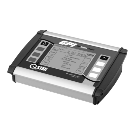
ASIX OMEGA User manual

OMEGA
Reference Manual
LOGIC ANALYZER

ASIX s.r.o.
Staropramenna 4
150 00 Prague
Czech Republic
www.asix.net
support@asix.net
sales@asix.net
ASIX s.r.o. reserves the right to make changes to this document, the
latest version of which can be found on the Internet.
ASIX s.r.o. renounces responsibility for any damage caused by the use
of ASIX s.r.o. products.
© Copyright by ASIX s.r.o.

Table of Contents
General Information 5
1
5
1.1 Product Overview
5
1.2 Package Contents
6
1.3 Panel Overview
6
1.4 Product Version
Getting started 7
2
7
2.1 Installation on Windows
7
2.2 Installation on Linux
7
2.3 Target connection
8
2.4 Acquire the data
Controls 9
3
9
3.1 Indicators and button
9
3.2 Target Connection
Using SIGMA & OMEGA Logic
Analyzers Software
11
4
11
4.1 Clock Source
11Modes of operation4.1.1
13Synchronous Clock Timing4.1.2
13
4.2 Input pins
13
4.3 Traces
14
4.4 Trigger Settings
15Basic Trigger Settings4.4.1
15Advanced Trigger Settings4.4.2
16Trigger Position within Acquisition4.4.3
17External Triggering4.4.4
17Other Trigger Settings4.4.5
18Amount of triggers4.4.6
19
4.5 Working with the acquired data
19Navigation and analysis4.5.1
20UART Protocol Decoder4.5.2
21SPI Bus Decoder4.5.3
21I2C Bus decoder4.5.4
22USB 1.1 Analyzer Plugin4.5.5
Installation 22
What to measure 23
Measure tool attachment 23
Measuring 23
Processing 23
Viewing 24
Searching 25
Linking the events window with the analyzer
window 26
Gathering of related communication into trees 26
26
4.6 Auxiliary functions
27Insider4.6.1
29Function Generator4.6.2
30
4.7 Frequency Measuring
30
4.8 Pin View
30
4.9 Availability of Auxiliary Functions
31
4.10 Using the Application for Automated
Acquisition
31
4.11 Command Line Interface omegacli.exe
32
4.12 Data streaming using Command Line
Interface omegartmcli.exe

32
4.13 Conversion to and from binary data
stream using bin2stf.exe a stf2bin.exe
33
4.14 Working with binary data stream using
binconvert.exe
33
4.15 Tips on working with binary data stream
33
4.16 Plugins
Using the Logic Analyzer 35
5
35
5.1 Sampling Frequency
35
5.2 Powering the Analyzer
36
5.3 Using the Application as a Portable
Application
Synchronization 38
6
38
6.1 Logic Analyzer Connection to PC when
Using Synchronization
38
6.2 Synchronization Interconnection
38Using Synchronization Cable6.2.1
39Interconnection of two Logic Analyzers6.2.2
39Interconnection of three Logic Analyzers6.2.3
39Interconnection of more than three Logic Analyzers6.2.4
40
6.3 Synchronization Accuracy
Using OMEGA Logic Analyzer under
Linux
41
7
OMEGA and SIGMA2 Comparison 43
8
Specifications 44
9
Document history 46
10

Page 5
1
General Information
1.1 Product Overview
OMEGA is a logic analyzer - development tool designated
for tracing and debugging of TTL (and compatible) digital
signals.
OMEGA Logic Analyzer is the highest performance logic
analyzer by ASIX s.r.o. from series of SIGMA/SIGMA2/
OMEGA Logic Analyzers.
The OMEGA Logic Analyzer is equipped with 512Mb
ofmemory (equivalent to 64MB) and provides with up to
16 digital inputs and sampling rate of 200Msps by a
single device. More inputs and memory can be utilized
using synchronization between multiple logic analyzers
units. Built-in data compression allows for tracing of long
running signals without exhausting logic analyzer
memory. When using all 16 inputs per analyzer,
guaranteed minimum capacity is over 29 million samples1
at full speed. OMEGA uses High-Speed USB2.0
(480Mbps) which ensures both data transfer and power
delivery with a single cable. There is no additional power
supply needed.
Features:
•Up to 16TTL compatible inputs per unit
•Synchronization between multiple units
•Up to 400Msps sampling rate (limited number of
inputs)
•External clock up to 99.95MHz
•512Mb of internal memory
•Real-Time mode utilizing the memory only as a FIFO
buffer
•Advanced hardware scompression
•Flexible trigger options
•USB interface for data and power
1.2 Package Contents
Please inspect the logic analyzer mechanically and
electrically upon receiving it. Unpack all items from the
shipping box and check for any obvious signs of physical
damage that may have occurred during transportation.
Report any damage to the shipping agent immediately.
We recommend to save the original packing carton for
possible future reshipment. Every logic analyzer is
shipped with the following contents:
•OMEGA Logic Analyzer
•Target cables:
•20 individual pins (SIGMACAB)
•one-to-one 20 pins (SIGCAB20)
•one-to-one 10 pins (SIGCAB10)
•USB cable (A-B)
•CD-ROM (software, drivers)
•Synchronization header
•Synchronization cable
•Optional accessory (must be ordered separately):
•Set of 10 variously colored hooks (PicoHook10)
Verify that all ordered items are included in the shipping
container. If anything is missing, please contact your local
distributor.

Page 6
1.3 Panel Overview
Fig.2: OMEGA Panel Overview
Panel Overview
1 USB port
2 Indication LEDs
3 Multifunction Start/Stop/Trigger button
4 Target interface
1.4 Product Version
The logic analyzer may come in different hardware or
software version. This manual reflects features and
options of logic analyzer software equipment Logic
Analyzer version 3.00. Updates to the latest version of
the software are always available free of charge on the
internet at www.asix.net. The main software comes with
many supporting utilities, which may be different version.
Trade Name
Serial Number
Availability
SIGMA
Since
A6010001
Since 2007
No longer
available
SIGMA 2
Since
A6020001
Since 2011
Low cost
OMEGA
Since
A6030001
Since 2012
Flagship
Table 1: Logic Analyzer Versions
The logic analyzer software supports basic functionality of
all logic analyzer hardware versions in the table, but
advanced features availability may differ. This manual
describes the hardware and software features available
only to the OMEGA Logic Analyzer.
Detailed comparison of the logic analyzers is in the
chapter OMEGA and SIGMA2 Comparison.
1 OMEGA will use approximately 18.1bits of memory per
16 input sample.

Page 7
2
Getting started
Before connecting and powering up the logic analyzer,
please review and go through all the instructions in this
chapter. You will learn all basic functions required to
debug your first application with the logic analyzer.
2.1 Installation on Windows
Install the ASIX SIGMA & OMEGA Application Package
available on CD or at www.asix.net to your computer.
Check the web page periodically for software updates.
Software updates are free and may address a discovered
problems and add new features. The OMEGA Logic
Analyzer is a USB device, therefore it requires USB
drivers. The drivers are installed automatically during
software package installation. Connect OMEGA to a USB
port or aUSB hub using supplied cable. In a while green
ON-LINE LED should turn on and the OMEGA Logic
Analyzer should appear in Device manager as correctly
installed.
2.2 Installation on Linux
The software for the OMEGA Logic Analyzer is designated
for Windows, but it runs on most distributions of Linux
using Wine.
For installation instructions of ASIX SIGMA & OMEGA
Application Package on Linux see the chapter Using
OMEGA Logic Analyzer under Linux.
2.3 Target connection
The OMEGA Logic Analyzer is equipped with 16 high
impedance inputs with logic levels compatible to TTL and
auxiliary Trigger In and Trigger Out pins.
Fig.3: Target connector
Always connect the ground between the application and
the analyzer and then connect desired input pins. The
OMEGA Logic Analyzer do not isolate ground between the
PC and the application.
If you want to use TriggerIn and TriggerOut pins, use
Settings ➙ Trigger Options..., tab Other Settings.
Warning:
Trigger In and Trigger Out pins are not 5V tolerant!
Note:
Capacitance and length of the probe cables should
be taken into consideration when connecting to a
debugged application, otherwise across-talks of fast
signals may occur. The leads of the supplied cable
with individual pins may be split to reduce
capacitance between adjacent wires for mid-range
signal speeds. For high-speed signals, using of any
cable is not recommended, it is recommended to
connect directly the logic analyzer to the application.

Page 8
2.4 Acquire the data
Start the application ASIX SIGMA & OMEGA Logic
Analyzers from start menu and launch the data
acquisition by pressing Enter. The OMEGA memory will
last most probably for minutes, so you can stop data
acquisition any time by pressing button Stop Acquisition
Now.
•To zoom, select a range with mouse or use key + or *
on keyboard.
•To take back last zoom operation, use key -,
Backspace or /.
•To move over the measured data, use arrow keys →, ←,
Page Down and Page Up, mouse wheel or hold Ctrl
key while moving mouse pointer.
• Using Alt+←/Alt+→ you can jump to next change on a
line where the mouse pointer is.
•Jump to another line is possible with arrows ↑ and ↓.
•To measure time or frequency or count number of
edges, use keys Spacebar, F and Q.
•To select a trigger, press T key and to use different
clocking options, press C key.
•OMEGA Logic Analyzer supports many auxiliary
functions. You can setup them with U key (U for
utilities).
Fig.4: Counting edges in an acquisition
To start using protocol analyzers, double click any trace
label on left margin of the window to add a new line.
Every new protocol analyzer is on a separate line, called
a trace.

Page 9
3
Controls
3.1 Indicators and button
Main panel contains two bi-color LED indicators providing
an operator with quick status information.
ONLINE / BUSY (green/yellow LED)
off: OMEGA is in low-power (Sleep) mode or no
USB driver has been installed (Windows
only) or no synchronization signal is being
received during Daisy-Chain operation
green: OMEGA is ready to operate
yellow: OMEGA is acquiring data
TRIGGER STATUS (red/yellow LED)
off: Trigger logic is inactive - no trigger
condition has been detected
red: OMEGA is waiting for trigger condition
yellow: flashes when trigger condition or trigger
pattern has been matched
The Go button helps to control the analyzer comfortably -
it cyclically switches among essential operation states.
When it is pressed in idle state the data acquisition is
launched. When it is pressed in running state the software
trigger is initiated. When it is pressed in triggered state 1
the acquisition is stopped, idle mode is launched and the
data transfer from logic analyzer memory to PC begins.
3.2 Target Connection
Fig.5: Target connector
The OMEGA Logic Analyzer is equipped with sixteen high
impedance inputs with TTL input logic levels and 1MΩ
pull-down resistors to park the pins when they are
unused. The functions Trigger In and Trigger Out are
available. The function Power Output2 is available on
Trigger In. The function of Synchronization (Daisy-Chain
connection) is available on the Trigger In/Trigger Out
pair.
Warning:
Trigger In and Trigger Out pins are not 5V tolerant!
If you want to use TriggerIn and TriggerOut pins, use
Settings ➙ Trigger Options..., tab Other Settings.
The digital inputs are organized as two 8-pin ports (inputs
1 to 8 are merged into port 1, inputs 9 to16 are merged
into port 2). Pin-to-pin skew between inputs on a single
port is rather low while it may beconsiderably higher
between the ports.
Always connect the ground between the application and
the analyzer and then connect desired input pins. OMEGA
Logic Analyzer do not isolate ground between the PC and
the application 3.

Page 10
min.
typ.
max.
VIL
input low voltage
0.8
V
VIH
input high voltage
2.0
V
VIN
absolute rating, inputs 1..16
-0.3
5.5
V
VIN
absolute rating, trigger I/O
-0.3
3.6
V
tsksp
pin-to-pin skew within single port
1
ns
tskbp
pin-to-pin skew between ports
4.8
ns
Table 2: Inputs Electrical Specifications
Note:
Capacitance and length of the probe cables should
be taken into consideration when connecting to a
debugged application, otherwise across-talks of fast
signals may occur. The leads of the supplied cable
with individual pins may be split to reduce
capacitance between adjacent wires for mid-range
signal speeds. For high-speed signals, using of any
cable is not recommended, it is recommended to
connect directly the logic analyzer to the application.
1 When using OMEGA Real-Time mode where is
unconstrained number of triggers, end of acquisition
can be performed by long pressing of the GO button.
2 Usage of any OMEGA-powered logic level translator is
possible thanks to possibility to power it from the logic
analyzer using Power Output feature on Trigger In pin.
3 When using a USB optoisolator designed for USB Full-
Speed (12Mbps) you will benefit from unique OMEGA
feature: The logic analyzer will download the data you
are currently looking at in preference. Therefore, the
data you are looking at will be available virtually in the
same time you will focus on them.

Page 11
4
Using SIGMA &
OMEGA Logic
Analyzers Software
4.1 Clock Source
4.1.1 Modes of operation
OMEGA can operate in one of several modes adapted to
actual user needs and particular debugged application
(number of inputs, sampling period etc...). The mode of
operation can be selected in Settings➙Clocksource.
Fig.6: Modes of operation
Available modes of operation:
Basic Mode
16inputs, sampling rate 200Msps.
Basic operation mode, sampling is derived
from internal oscillator.
Daisy Chain Mode
16×n inputs, sampling rate 200Msps.
Several OMEGA Logic Analyzers connected
together with a synchronization cable.

Page 12
Higher Sampling Rate Mode
8inputs, sampling rate 400Msps.
Number of input pins is reduced to eight
with benefit of twice sampling rate. Inputs
are limited to single port due to higher
demands on the delay skew between
inputs.
Real-Time Mode
16 inputs, sampling rate 200Msps.
The whole internal memory works as FIFO
buffer and data are streamed in real-time
to the PC. This mode is very memory
demanding, therefore lot of free RAM and
free space on hard drive is required.
Synchronous Clock Mode
15 inputs, external clock.
Input1 is utilized as external clock input.
Rising or falling sampling edge or both
(DDR) can be chosen. Clock speed should
be within the range of ~100kHz to
99.95MHz. Due to internal pipeline circuits,
the clock signal must be present before
start of the data acquisition and some time
after the end of the acquisition otherwise
several last samples will not be contained
in the captured data. Using this mode for
measuring synchronous bus (e.g. processor
bus) can be advantageous. The
synchronous clock can be used with or
without asynchronous time information1.
Synchronous clock Mode Without Asynchronous
Time Scale The OMEGA Logic Analyzer tries optionally
to measure the clock speed with auxiliary
low resolution frequency counter and uses
this information for time scale. Because
time information is not included in the
acquisition data, the memory usage is
lower compared to the mode with
Asynchronous Time Scale enabled.
Synchronous clock Mode With Asynchronous Time
Scale With external clock frequencies <40MHz,
The OMEGA Logic Analyzer can together
with the data also save the time with
resolution 10ns. Higher frequencies up to
the maximum possible external clock
frequency are allowed, but the accuracy is
degraded due to higher utilization of the
clock synchronization circuitry. It is not
possible to use both DDR and
Asynchronous Time Scale at the same
time.
Fig.7: Clock not present on Input 1 during OMEGA
Synchronous Clock Mode
The clock on Input 1 must be continuous and present
before the acquisition starts.
Note:
Data compression (RLE and Huffman coding) is used
in every case, disregarding selected mode, giving
possibility tocapture long time running signals with
precise timing. The actual compression ratio
depends oncharacteristics of the particular signal.

Page 13
4.1.2 Synchronous Clock
Timing
Fig.8: Synchronous clock timing
The synchronous clock timings are measured at the input
connector. At the maximum clock rates, use of custom
cables and amplifiers may be necessary.
Delay
Class
Typical
Maximum
Inputs 2-8
Maximum
Inputs 9-16
Setup
tsetup
Hold
thold
Setup
tsetup
Hold
thold
Setup
tsetup
Hold
thold
1
0.10
1.10
1.10
2.10
4.90
5.90
ns
2
-0.15
1.45
0.85
2.45
4.65
6.25
ns
3
-0.40
1.10
1.10
2.10
4.90
5.90
ns
4
-0.90
2.45
0.10
3.45
3.90
7.25
ns
5
-1.10
2.70
-0.10
3.70
3.70
7.50
ns
6
-1.40
3.10
-0.40
4.10
3.40
7.90
ns
7
-1.80
3.55
-0.80
4.55
3.00
8.35
ns
8
-1.95
3.75
-0.95
4.75
2.85
8.55
ns
Table 3: Synchronous Clock Timing
Delay Class can be selected in a dialog Settings ➙ Clock
Source. All inputs must be set up for the same Delay
Class.
4.2 Input pins
The term input pin refers to physical input of OMEGA
Logic Analyzer. The logic analyzer use fixed input
threshold levels compatible with TTL or 5V / 3.3V CMOS. If
a particular input is not required by user, but its value
differs from logic 0, OMEGA can disable some of the
unused inputs to save amount of required memory for
data acquisition. If the unused pins are in logic 0 (weak
internal pull-down will guarantee this), the amount of
saved memory is negligible.
The number and placement of used input pins can be
selected in Inputs Dialog. The dialog can be opened using
Settings ➙ Inputsmenu or using I hotkey.
4.3 Traces
The term trace refers to visualization of acquired data. A
trace can be composed of several inputs as well,
otherwise a single input may be used in multiple traces,
e.g. it is possible tovisualize several inputs as a bus while
still having the possibility to display individual signals.
Traces are defined in Traces dialog. The dialog can be
opened by double-clicking a name of each trace in the
main viewer window, using Settings ➙ Tracesmenu or
using Ctrl+T hotkey.

Page 14
Fig.9: Traces Dialog
Traces Dialog
1
List of traces
The selected trace is being edited.
2
Trace caption
Trace caption can have arbitrary name. Common
negation characters in the expression are treaded
as a negation.
3
Trace color
The color is mixed with color for logic 0 and logic 1.
4
Input selector
When the selector selects a decoder, it can be
directly configured via Plugin Config... button (8).
5
Bus number setup
Any textual prefix and suffix can be selected, radix can be
in range of 2 to 36.
6
Add and Delete Trace buttons
Click the button to add a new trace or delete one.
7
Trace move buttons
Click the button to move the trace up and down.
The shortcut to use the buttons is Shift+↑ and Shift
+↓.
8
Plugin Config Dialog
When a decoder is selected as source of the data,
the configuration of the decoder can be invoked by
pressing the Plugin Config Dialog button.
If a trace is defined as a bus, thevalue on the bus will be
displayed according to configurable formatting. Radix
from 2 to 36 can be used to format thevalue as a number
using alphabetical characters A-Z for digits 10-35. There
is also special formatting option for displaying data as
ASCII characters; values which do not represent a
printable character in selected set are shown as
hexadecimal numbers. The output may be prefixed by a
text, suffixed by a text or padded with zeros from the left
to given particular width and likewise digit grouping can
be used.
4.4 Trigger Settings
Trigger options are defined in the Trigger settings dialog.
The dialog can be invoked from menu by Settings ➙
TriggerSetup or using a T hotkey.
Availability of certain trigger settings depends on clock
settings. For higher sample rates, only basic trigger on an
edge of a selected input signal is available. In the other
modes either a pin trigger or an advanced trigger can be
used. The advanced trigger allows user to set up precise
specification of a trigger condition.

Page 15
4.4.1 Basic Trigger
Settings
Fig.10: Basic Trigger Settings
Basic trigger settings define a trigger event as a
combination of desired levels and edges on input pins.
Note:
Although setting the edge detector on more than
one input pin lacks a little sense, it is possible to set
the edge detector on up to two input pins. The
acquisition is then triggered only when an edge is
detected within one clock period of the detector
logic, which is 10 ns. This can be somehow useful for
race condition hunting, but the probability of the
detection is disputable.
The trigger can occur immediately (occurs as soon as the
defined combination turns up) or delayed by a counter.
4.4.2 Advanced Trigger
Settings
Advanced trigger settings define the trigger event by a
set of boolean expressions in combination with an
advanced event and delay counter.
Fig.11: Advanced Trigger Settings
Advanced Trigger Dialog Overview
1
Advanced Trigger Selector
2
Trigger Mask

Page 16
The mask made of any number of inputs can be
selected. The inputs in the mask can be either
ANDed, ORed, NANDed or NORed, but not their
combination.
3
Boolean Function between Masks
There can be any boolean function of list AND, NAND,
OR, NOR, XOR, XNOR.
4
Adder of new Functions and Masks
A new function and a mask can be added by clicking the
adder mark.
5
Inversion or Edge Detector
Nothing, inversion or any edge detectors can be set
up here. The detector include rising edge, falling edge
and any edge.
6
Precondition toggle button
A precondition can be enabled and disabled by
clicking on the precondition button. The trigger is then
detected only when a boolean condition is matched after at
least one occurrence of the precondition.
7
Advanced event and delay Counter
The event and delay counter enables a time and
count related condition.
8
Lower than / Higher than / Constraints toggle
button
By clicking the length button the condition will toggle
between a Lower than / Higher Than / Constraints
condition.
9
Value with prescaler
The value of the counter. Due to a prescaler, the
value may be rounded to nearest value achievable
with the prescaler.
10
Unit selector
Note:
There are three masks available for the condition
and precondition in total. The condition must use at
least one, therefore at most two masks are available
for the precondition.
Fig.12: Advanced Trigger Masks
Mask selection
1
Edge and inversion selector
2
Input or trace Term
The term can also have negation and in case of busses
constant comparison
2.
3
Mask function selector
The selector can be either AND or OR.
4
Add new input term
5
Delete one term
Although this approach makes the description of very
complex situations possible, accordingly it allows to
define the moment to be captured precisely, there are
certain limitations determined by capabilities ofthe
hardware. If the expression is too complex to be
implemented in the OMEGA Logic Analyzer hardware, an
exclamation icon appears to indicate this fact.
4.4.3 Trigger Position
within Acquisition
The Post-Trigger Time can be selected on the Other
Trigger Settings tab of the Trigger Settings dialog.
This Post-Trigger Time selects the amount of logic
analyzer memory which can be used after the acquisition
was triggered. The rest of the memory is used as Pre-

Page 17
Trigger Time. If the trigger was detected before the
whole Pre-Trigger Time memory was wasted, the
remaining memory will not be used, even for the Post-
Trigger acquisition. If the amount of the memory used is
greater than the Pre-Trigger memory amount, the very
beginning of the acquisition is dropped.
The Post-Trigger Time setting can be set from range of
1-99% with resolution of 1%. The accuracy of the setting
is within ±1%.
4.4.4 External Triggering
The OMEGA Logic Analyzer comes with Trigger In and
Trigger Out pins (on the SIGCAB20 cable described as TI
and TO). The Trigger Out can be configured as
3.3VCMOS output with negative or positive polarity or as
an open collector output. The Trigger Out pulse length
can be set to either 1µs or 1ms.
The Trigger In input can be configured as positive or
negative polarity. The function of Power Out can be
configured on Trigger In.
The Trigger In and Trigger Out pins are shared with Daisy
Chain functionality on the OMEGA Logic Analyzer.
The source of the activation of the Trigger Out pin can be
selected from variety of sources:
•By external Trigger In.
•By trigger by trigger condition.
•By trigger by Go button.
•By trigger in PC software.
•During acquisition.
•During acquisition after it has been triggered.
Min.
Typ.
Max.
VIL
input low voltage
0.8
V
VIH
input high voltage
2.0
V
VIN
absolute rating, trigger I/O
-0.3
3.6
V
VPO
power output on Trigger In
2.0
2.4
3.3
V
I
PO
power output on Trigger In
100
mA
Table 4: Electrical Specification on the Trigger In/Out Pin
Warning:
The absolute maximum voltage on the Trigger In
and Trigger Out pins is 3.6V.
4.4.5 Other Trigger
Settings
During normal acquisition, the acquisition is triggered by
first occurrence of the trigger from beginning of the
acquisition. If any successive triggers are detected, they
are ignored by the Post-Trigger acquisition termination
logic, but the Trigger LED can be configured to either
blink on every detected trigger or only on the first trigger
launching the acquisition.

Page 18
4.4.6 Amount of triggers
When using OMEGA Real-Time Mode, the trigger is being
detected and stored during whole acquisition, not only for
the first time to trigger the acquisition.
Fig.13: Time scale around trigger
The time scale zero time can be set to:
•The beginning of the acquisition.
•The first trigger.
•The last trigger.
The viewer can be set to display:
•Only the first trigger.
•Only the last trigger.
•Every trigger.
Note:
Setting the trigger as an event which is very often
(e.g. rise edge of a communication clock) is highly
discouraged in the real-time mode because the
trigger is stored in the FIFO and consumes significant
amount of the buffer. The performance of the
software is also reduced when displaying lot of
triggers.
Trigger Filter
The trigger filter is a filter which reduces the number of
triggers to one per millisecond, but allowing bursts of up
to 256 triggers. The filter should be always turned on
during normal operation.

Page 19
4.5 Working with the
acquired data
4.5.1 Navigation and
analysis
Navigation in the main viewer can be controlled by
keyboard, mouse or by a combination of both.
Action
Key or mouse action
Viewer window sliding along the
time axis
← or →
mouse wheel
Ctrl and mouse move
Zoom
+ or -
Ctrl and mouse wheel
Select by mouse drag
Undo last zoom / move
Backspace
Zoom 50× in
*
Zoom whole acquisition
3
/
Jump to acquisition end3
End
Jump to trigger
3
Home
Move mouse to another trace
↑ or ↓
Jump to next edge on selected
trace
Alt+→ or Alt+←
Place bookmark
Ctrl+Shift+0 to 9
Jump to bookmark
Ctrl+0 to 9
Place marker
Space
Count number of edges
Q
Toggle between period and
frequency
F
Display counting options
QQ
Table 5: Mouse and Keyboard action for navigation and analysis

Page 20
Fig.14: Counting edges in an acquisition
Note:
Several functionality of the software is coded in
plugins. All described functionality is within plugins
distributed together with the software. By disabling
or replacing the plugins, the functionality will differ.
4.5.2 UART Protocol
Decoder
This decoder decodes captured UART signal and displays
ASCII characters, decimal or hexadecimal values.
Fig.15: UART Decoder
Several options can be set up:
Input The input pin.
Line Polarity
The polarity of the line. This is useful when
using direct connection of voltage limited
RS-232 (be aware of maximum ratings on
OMEGA pins).
Table of contents
