bonitron M3452ON User manual

Model M3452ON
Active Braking Indicator
Customer Reference Manual

Bonitron, Inc.
2
Bonitron, Inc.
Nashville, TN
An industry leader in providing solutions for AC drives.
ABOUT BONITRON
Bonitron designs and manufactures quality industrial electronics that improve the reliability of
processes and variable frequency drives worldwide. With products in numerous industries, and
an educated and experienced team of engineers, Bonitron has seen thousands of products
engineered since 1962 and welcomes custom applications.
With engineering, production, and testing all in the same facility, Bonitron is able to ensure its
products are of the utmost quality and ready to be applied to your application.
The Bonitron engineering team has the background and expertise necessary to design, develop,
and manufacture the quality industrial electronic systems demanded in today’s market. A strong
academic background supported by continuing education is complemented by many years of
hands-on field experience. A clear advantage Bonitron has over many competitors is combined
on-site engineering labs and manufacturing facilities, which allows the engineering team to have
immediate access to testing and manufacturing. This not only saves time during prototype
development, but also is essential to providing only the highest quality products.
The sales and marketing teams work closely with engineering to provide up-to-date information
and provide remarkable customer support to make sure you receive the best solution for your
application. Thanks to this combination of quality products and superior customer support,
Bonitron has products installed in critical applications worldwide.

Bonitron, Inc.
3
AC DRIVE OPTIONS
In 1975, Bonitron began working with AC inverter drive specialists at synthetic fiber plants to
develop speed control systems that could be interfaced with their plant process computers. Ever
since, Bonitron has developed AC drive options that solve application issues associated with
modern AC variable frequency drives and aid in reducing drive faults. Below is a sampling of
Bonitron’s current product offering.
WORLD CLASS PRODUCTS
Undervoltage Solutions
Overvoltage Solutions
Uninterruptible Power for Drives
(DC Bus Ride-Thru)
Voltage Regulators
Chargers and Dischargers
Energy Storage
Braking Transistors
Braking Resistors
Transistor/Resistor Combo
Line Regeneration
Dynamic Braking for Servo Drives
Common Bus Solutions
Portable Maintenance Solutions
Single Phase Power Supplies
3-Phase Power Supplies
Common Bus Diodes
Capacitor Formers
Capacitor Testers
Power Quality Solutions
Green Solutions
12 and 18 Pulse Kits
Line Regeneration

M3452ON
4
This page intentionally left blank

Table of Contents
5
1. INTRODUCTION..........................................................................................................................7
1.1. Who Should Use...........................................................................................................................7
1.2. Purpose and Scope........................................................................................................................7
1.3. Manual Version and Change Record............................................................................................7
Figure 1-1: Model M3452ON......................................................................................................................7
2. PRODUCT DESCRIPTION............................................................................................................9
2.1. Related Products...........................................................................................................................9
2.2. Part Number Breakdown ..............................................................................................................9
2.3. General Specifications..................................................................................................................9
Table 2-1: General Specifications Chart......................................................................................................9
2.4. General Precautions and Safety Warnings .................................................................................10
3. INSTALLATION INSTRUCTIONS................................................................................................11
3.1. Environment ...............................................................................................................................11
3.2. Unpacking................................................................................................................................... 11
3.3. Mounting ....................................................................................................................................11
3.4. Wiring and Customer Connections............................................................................................. 11
Figure 3-1: Typical Interconnection Diagram ...........................................................................................12
3.4.1. Power Wiring..................................................................................................................................12
3.4.2. I/O Wiring.......................................................................................................................................12
Table 3-1: Wiring Specifications...............................................................................................................13
4. OPERATION..............................................................................................................................15
4.1. Functional Description ...............................................................................................................15
4.2. Features....................................................................................................................................... 15
4.2.1. Connectors ......................................................................................................................................15
4.2.2. Output Selection Switch..................................................................................................................15
Table 4-1: Output Switch selections..........................................................................................................15
4.2.3. Test Mode (Position 9)....................................................................................................................16
Figure 4-1: Front View..............................................................................................................................17
5. MAINTENANCE AND TROUBLESHOOTING...............................................................................19
5.1. Troubleshooting..........................................................................................................................19
6. ENGINEERING DATA................................................................................................................21
6.1. Dimensions and Mechanical Drawings ......................................................................................21
Figure 6-1: M3452ON Chassis Dimensional Outline Drawing.................................................................21

M3452ON
6
This page intentionally left blank

User’s Manual
7
1. INTRODUCTION
1.1. WHO SHOULD USE
This manual is intendedfor use by anyone who is responsiblefor integrating, installing,
maintaining, troubleshooting, or using this equipment with any DC energy storage
system.
Please keep this manual for future reference.
1.2. PURPOSE AND SCOPE
This manual is a user’s guide for the Model M3452ON Active Braking Indicator. It will
provide the user with the necessary information to successfully install, integrate, and
use the M3452ON.
In the event of any conflict between this document and any publication and/or
documentation related to the system, the latter shall have precedence.
1.3. MANUAL VERSION AND CHANGE RECORD
Rev 00 is the original release of the M3452ON manual.
Updates to About Bonitron were made in Rev 00a.
The manual template was updated in Rev 00b.
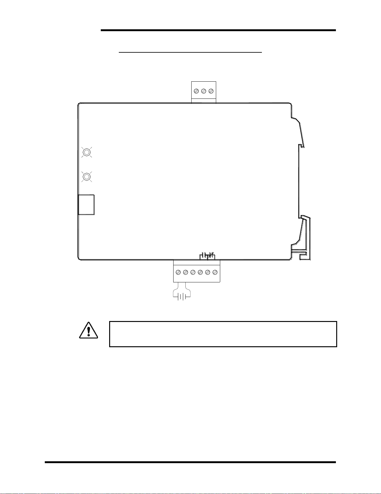
Figure 1-1: Model M3452ON

M3452ON
8
This page intentionally left blank

User’s Manual
9
2. PRODUCT DESCRIPTION
The M3452ON Active Braking Indicator has been designed for use with the M3452 high
current braking chopper series. It is intended to provide a contact that may be used to
indicate braking activity. The M3452ON module is intendedto connect to the Master/Slave
control signal of the standard braking modules and provide a Form C MOSFET output
isolated from the input. The Form C output may follow the input signal directly or provide
a signal with a selectable minimum pulse width.
2.1. RELATED PRODUCTS
This product is designed for use with any M3452 braking chopper with Master/Slave
control signal connections. Contact your distributor for more information.
2.2. PART NUMBER BREAKDOWN
BASE MODEL NUMBER
The Base Model Number, M3452, indicates that the unit is related to braking modules.
‘ON’ specifies a buffer board and ‘M1’ specifies the version.
There are no special options at this time.
2.3. GENERAL SPECIFICATIONS
Table 2-1: General Specifications Chart
PARAMETER
SPECIFICATION
Power
24VDC ± 10%, 100 mA
Input Signal
Control Signal from M3452 Braking Chopper
Outputs
Active braking
Form C Solid State Relay,
250V, 100mA, 35 Ω
Operation Temperature
0ºC to +40ºC
Storage Temperature
-20ºC to +65ºC
Humidity
Below 90% non-condensing
Atmosphere
Free of corrosive gas and dust

M3452ON
10
2.4. GENERAL PRECAUTIONS AND SAFETY WARNINGS
DANGER!
HIGH VOLTAGES M AY BE PRES ENT!
FAILURE TO HEED THESE WARNINGS MAY
RESULT IN SERIOUS BODILY INJURY OR DEATH!
CAUTION!
NO USER-SERVICEABLE PARTS ARE CONTAINED WITHIN
THIS PRODUCT.
INOPERABLE UNITS SHOU LD BE REPLACED OR RETURNED
FOR EVALUATION AND /OR REPAIR BY QUALIFIED
TECHNICIANS
BEFORE ATTEMPTING INS TALLATION OR REM OVAL OF
THIS PRODUCT,BE SURE TO REVIEW DOCUMENTATION OF
ALL CONNECTED DEVISE S FOR PERTINENT SAFETY
PRECAUTIONS.
INSTALLATION AND/OR REMOVAL OF THIS PRODUCT
SHOULD ONLY BE ACCOM PLISHED BY A QU ALIFI ED
ELECTRICIAN IN ACCOR DANCE WITH NATIONAL
ELECTRICAL CODE OR EQUIVALENT REGULATIONS.
ANY QUESTIONS AS TO APPLICATION, INSTALLATION OR SERVICE
SAFETY SHOULD BE DIRECTED TO THE EQUIPMENT SUPPLIER.

User’s Manual
11
3. INSTALLATION INSTRUCTIONS
WARNING!
Installation and/or removal of this product should only be performed by a
qualified electrician in accordance with National Electrical Code or local
codes and regulations.
Proper installation of the Model M3452ON Active Braking Indicator is described below.
Please direct all installation and start up inquiries regarding this product to your supplier
or system integrator.
3.1. ENVIRONMENT
The installation site should be dry and clean without extreme temperatures.
3.2. UNPACKING
Upon receipt of this product, please verify that the product received matches the
product that was ordered and that there is no obvious physical damage to the unit. If
the wrong product was received or the product is damaged in any way, please contact
the supplier from which the product was purchased.
3.3. MOUNTING
The unit is mounted with a standard DIN rail clip attached to the back of the enclosure.
Refer to Figure 6-1 to determine the correct mounting dimensions for your unit.
3.4. WIRING AND CUSTOMER CONNECTIONS
This section provides information about the field connection of the M3452ON Active
Braking Indicator.
Be sure to review all system documentation as well as the power wiring information in
Section 3.4.1 before proceeding.
For the maximum wire size accepted by the individual field connection terminals, refer
to Table 3-1. Wire types and sizes should be chosen in accordance with national and
local electrical codes to meet the voltage and current levels present for your
application.
Figure 3-1 shows a typical interconnection of the M3452ON with a typical braking
chopper and I/O signals.
M3452ON
12
Figure 3-1: Typical Interconnection Diagram
ACTIVE BRAKING INDICATOR
M3452ON-M1
FROM M3452 BRAKING UNIT
MASTER / SLAVE SIGNAL
NO C NC
6
CONTACTS
ACTIVE
+
OUTPUT
SELECT
WIDTH
PULSE
POWER LED
5
4
3
21
TB2
POWER
24Vdc
+ -
ACTIVE LED
SIGNAL
- +
INPUT
23
1
TB1
WARNING!
Only qualified electricians should perform and maintain the interconnection
wiring of this product. All wiring should be done in accordance with
National Electrical Code or equivalent regulations.
3.4.1. POWER WIRING
This unit requires an external 24Vdc power supply . The system must be
supplied with at least 100 mA at 24VDC +/- 10% to guarantee correct
operation.
3.4.2. I/O WIRING
The Input Signal connector should only be connected to the Master/Slave
control signal of a M3452 Braking Transistor. The Output Contacts ratings
are listed in the table below.
Dwg: 100044 Rev: 20100323

User’s Manual
13
Table 3-1: Wiring Specifications
TERMINAL
FUNCTION
ELECTRICAL
SPECIFICATIONS
MIN
WIRE
AWG
MAX
WIRE
AWG
TORQUE
TB1-1
Signal Input +
0-30VDC to TB1-3
28
16
.22-.25 Nm
TB1-2
No Connection
TB1-3
Signal Input -
Common to TB1-1
28
16
.22-.25 Nm
TB2-1
Power Input +
+24VDC to TB2-2
28
16
.22-.25 Nm
TB2-2
Power Input -
24VDC common to TB2-1
28
16
.22-.25 Nm
TB2-3
No Connection
TB2-4
NO Output Contact
250V AC/DC 120mA Max
28
16
.22-.25 Nm
TB2-5
Contact Common
250V AC/DC 120mA Max
28
16
.22-.25 Nm
TB2-6
NC Output Contact
250V AC/DC 120mA Max
28
16
.22-.25 Nm

M3452ON
14
This page intentionally left blank

User’s Manual
15
4. OPERATION
4.1. FUNCTIONAL DESCRIPTION
The M3452ON Module monitors the signal from the standard M3452 Braking
Transistor module and provides isolated output contacts that follow the input. The
output pulse width may be adjusted for longer on-state periods for use by other
devices. The module uses a 10 position switch to select the output pulse width.
4.2. FEATURES
4.2.1. CONNECTORS
4.2.1.1. TB1 –1&3(INPUT SIGNAL)
The input signal connector accepts the control signal from an M3452
braking transistor. This signal is a 24Vpk pulse which may vary from a
200µS to 10mS. The signal from the M3452 unit may be common to the
Negative DC Bus and wire should be rated for 600V. The input signal is
optically isolated from all other connections on the M3452ON.
4.2.1.2. TB2 –1&2 (POWER)
The power input accepts 24VDC to supply power to the voltage monitor
board.
4.2.1.3. TB2–4, 5, &6 (FORM COUTPUT CONTACT)
The output contact is composedof a Form C optomosrelay. The optomos
relay is much faster than a mechanical relay allowing lower input to output
delays. This relay will accept AC and DC voltages up to 250V and a
current of 120mA. For loads requiring more current, buffer relays may be
needed.
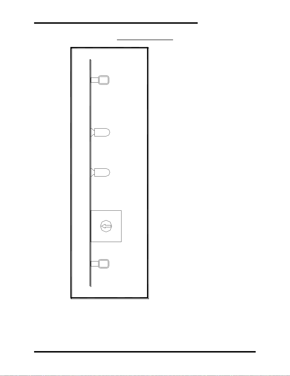
4.2.2. OUTPUT SELECTION SWITCH
4.2.2.1. RANGE (POSITION 0TO 8)
The Output Selection Switch allows the user to choose the output pulse
time when an input signal is received. The output contact times may be
found in the following table.
Table 4-1: Output Switch selections
SELECTION
OUTPUT
0
= INPUT
1
= INPUT + 100mS
2
= INPUT + 200mS
3
= INPUT + 300mS
4
= INPUT + 400mS
5
= INPUT + 500mS
6
= INPUT + 1 Sec
7
= INPUT + 2 Sec
8
= INPUT + 5 Sec
9
TEST MODE 1 Sec Off/On

M3452ON
16
4.2.3. TEST MODE (POSITION 9)
Test mode is used to insure the wiring for the output of the module is correct.
In test mode, the output will cycle on and off at 1 second intervals regardless
of the input.
To enter test mode:
1. Remove 24V power from the module.
2. Select Position “9” on the output selection switch.
3. Apply 24V power from the module.
4. Output will cycle.
5. When finished testing, select a different switch position and cycle power.
Note: Unit will stay in test mode until power is cycled.
User’s Manual
17
Figure 4-1: Front View
COMMON Test Point
SIGNAL Test Point
SELECTION
POWER LED
ACTIVE SIGNAL LED
9
6
8
7
2
1
0
3
5
4
PULSE
OUTPUT
Dwg: 100045 Rev: 20100323

M3452ON
18
This page intentionally left blank

User’s Manual
19
5. MAINTENANCE AND TROUBLESHOOTING
5.1. TROUBLESHOOTING
If a problem occurs on start-up or during normal operation, refer to the problems
described below. If a problem persists after following the steps below, contact the
product supplier or your system integrator for assistance.
Repairs or modifications to this equipment are to be performed by Bonitron approved
personnel only. Any repair or modification to this equipment by personnel not
approved by Bonitron will void any warranty remaining on this unit.
OUTPUT CONTACTS DO NOT CHANGE
Remove power and set selection switch to position “9”. Apply power and the Power
LED should be on as well as Signal LED pulsing in 1 second intervals. The output
contacts should be following the Signal LED. The Output contacts should read
approximately 30 ohms when closed. If the module functioned properly during the
preceding step you may set the selection switch back to the desired mode. Verify the
connection including polarity on the Input Signal and check for proper operation again.
If the module does not operate correctly during this step, contact Bonitron.

M3452ON
20
This page intentionally left blank
Table of contents
Popular Measuring Instrument manuals by other brands


Fluke
Fluke SMFT-1000 Calibration manual

Greenlee
Greenlee 93-172 instruction manual

Brooks
Brooks 1250-55 Series Installation and operation manual

Thermo Scientific
Thermo Scientific Orion Star A216 reference guide

Reed Instruments
Reed Instruments R3530 instruction manual

VOLTCRAFT
VOLTCRAFT PA-10 operating instructions

Titan
Titan Metraflow 240-020 instruction manual

AQUASCAN INTERNATIONAL
AQUASCAN INTERNATIONAL DX-300 operating instructions

PCB Piezotronics
PCB Piezotronics 353B77 Installation and operating manual

Spirent
Spirent NOMAD UX Operation guide

SAEHAN
SAEHAN DHD-3 user manual

Badger Meter
Badger Meter Preso Gemini Cone user manual