Asko D3mmmXL User manual

Page1
AA
AA
AUTUT
UTUT
UTOMAOMA
OMAOMA
OMATIC HIGH LTIC HIGH L
TIC HIGH LTIC HIGH L
TIC HIGH LOOPOOP
OOPOOP
OOP
TT
TT
The drhe dr
he drhe dr
he drain hose is fain hose is f
ain hose is fain hose is f
ain hose is fastened to the bacastened to the bac
astened to the bacastened to the bac
astened to the backk
kk
k
ofof
ofof
of the macthe mac
the macthe mac
the machine ahine a
hine ahine a
hine at the best height.t the best height.
t the best height.t the best height.
t the best height.
TT
TT
Too
oo
o
eliminate potential drain problems,eliminate potential drain problems,
eliminate potential drain problems,
lealea
lealea
leavv
vv
ve this hose in place
e this hose in place
e this hose in placee this hose in place
e this hose in place..
..
.
IMPORTANT!
Read all of these instructions
before installing the dishwasher.
SAVE THESE INSTRUCTIONS FOR FUTURE REFERENCE
Introduction 2
What You Need 2
Dimensions 3
Preparing the Location 3
Water Supply 4
Drain Connections 5
Electrical Connections 6
Preparing the Dishwasher for Installation 6
Moving the Machine into Place 7
Connecting the Electric Cable 8
Connecting the Water Supply 8
Adjusting the Leveling Legs 9
Fastening the Dishwasher to the Cabinet 9
Installing the Toe Kick 9
Fitting the D3252XLFI, D3532XLFI, and D3532XLFIWS Custom Door
Panel 10
Index 12
CONTENTSCONTENTS
CONTENTSCONTENTS
CONTENTS
ASKO XL TALL TANK
DISHWASHER
INSTALLATION
INSTRUCTIONS

Page2
TOOLSTOOLS
TOOLSTOOLS
TOOLS
1) Phillips No. 2 screwdriver
2) Flat blade screwdriver
3) Torx screwdriver size T 20
4) Adjustable wrenches (if you use copper fittings)
5) Open-ended wrench (1/2" [12 mm] or 5/8" [16 mm])
6) Tape measure
7) Spirit level
8) Electric drill with 1” drill bit
9) Keyhole saw
MAMA
MAMA
MATERIALSTERIALS
TERIALSTERIALS
TERIALS
♦Minimum 3/8" OD copper tubing of sufficient length
for your installation
♦Shut-off valve and fittings for water supply line
Tip Guards (optional)Tip Guards (optional)
Tip Guards (optional)
When it is not possible to attach the
dishwasher to the cabinet or the
underside of the cabinet top, you
should install tip guards to prevent the
machine from tipping when you open
the door.
Refer to page 4 for installation
instructions.
TECHNICAL DTECHNICAL D
TECHNICAL DAA
AA
ATT
TT
TAA
AA
A
Water pressure 18-176 psi
Power 120 V, 60 Hz, 15 amp.
Heating element 1200 W
Max loading 1300 W
Read these instructions carefully and completely before
you install the machine. The installation should be
carried out by a qualified person who is familiar with all
local codes and ordinances for electrical and plumbing
connections.
If a dishwasher is being installed in this area for the
first time, most of the cabinet work, plumbing, and
electrical has to be done before you move the machine
into place.
NOTE: Cosmetic damage must be reported to the
ASKO dealer within five days fromthe dateofpurchase.
As soon as you unpack the dishwasher, thoroughly
check it for cosmetic damage.
If you are replacing an old dishwasher, you must check
the plumbing connection and wiring before you move
the new dishwasher into place.
Tip Guards
(P/N 8070851)
INTRODUCTIONINTRODUCTION
INTRODUCTION
WHAWHA
WHAWHA
WHATT
TT
T YY
YY
YOU NEEDOU NEED
OU NEEDOU NEED
OU NEED
The dishwasher is shipped with the high loop drain
hose, inlet hose and electrical cord attached and ready
to be connected.

Page3
UNIT DIMENSIONSUNIT DIMENSIONS
UNIT DIMENSIONS
US Metric
Measurements Measurements
Height 34" - 37" 864 - 939 mm
Width 24" 610 mm
Depth 23-5/8" 600 mm
Depth w/door open 48” 1219 mm
Weight 104 lb 48 kg
DIMENSIONSDIMENSIONS
DIMENSIONS
The best place for your dishwasher is in the kitchen
near the sink. This makes it easier to connect the water
and drain supply lines.
A built-in dishwasher must be enclosed on the top, both
sides and the back.
The electrical and water supplies should enter through
the area indicated by the shading on the illustration at
right.
Access holes must be round and smooth, and they
should be 1-1/2” (38mm) in diameter.
EUREUR
EUREUR
EUROPEAN INSTOPEAN INST
OPEAN INSTOPEAN INST
OPEAN INSTALLAALLA
ALLAALLA
ALLATIONSTIONS
TIONSTIONS
TIONS
The kick plate supplied with your dishwasher fits a 24"
(610 mm) opening. When using European standard
installation, a 23-1/2” (597 mm) wide toe kick is available
from yourASKO dealer. (Part numbers: White=8073566-
0, Black=8073566-29, Metallic=8073566-81,
Bisque=8059758-84)
PREPPREP
PREPPREP
PREPARINGARING
ARINGARING
ARING THE LTHE L
THE LTHE L
THE LOCAOCA
OCAOCA
OCATIONTION
TIONTION
TION
CABINET OPENINGCABINET OPENING
CABINET OPENING
US Metric
Measurements Measurements
Height 34" - 37" 864 - 939 mm
Width 24-1/8” 613 mm
Depth 23-5/8" 600 mm
2-1/4"
57 mm
6-1/4"
159 mm
34" - 37"
864 - 939 mm
23-5/8"
600 mm
48"
1219 mm
Door
6-1/4" - 8-1/4"
159 - 210 mm
1½”
38 mm
24"
610 mm
23-7/16"
596 mm
24-1/8"
613 mm
34" - 37"
860 - 920 mm
1½”
38 mm
6-1/4" to 8-1/4"
159 to 210 mm

Page4
WARNING! Plumbingconnections must complywith
applicablesanitary, safety and plumbing codes in your
area.
The machine can be connected to either a hot or cold
water supply. If a cold water supply is used, the washing
times will be longer but the performance will not be
affected.
The dishwasher comes with a 6-foot PEX water supply
line that has a 3/8" NPT female connection.
After determining where the water supply line will enter
under the sink, drill a 1-1/2" (38 mm ) access hole and
runthe line to the approximate inlet valvelocation shown
in the figure below. The water line inlet valve is on the
right rear of the machine.
For service convenience, a shut-off valve (not supplied)
should be installed in the supply line in an easily
accessible location, such as, beneath the sink.
It is important that the water supply line and the shut-off
valve have a sufficient flow volume. At last 3 gallons (12
liters) per minute must be able to pass through the
line. The water pressure should be 18-176 psi.
CORNER INSTCORNER INST
CORNER INSTALLAALLA
ALLAALLA
ALLATIONTION
TIONTION
TION
2” clearance
If the dishwasher is installed in a corner, there must be
a minimum clearance of 2” (50 mm) from the side wall
so the door can open.
EE
EE
EASYASY
ASYASY
ASYII
II
INSTNST
NSTNST
NSTALLALL
ALLALL
ALL CONNECTIONSCONNECTIONS
CONNECTIONSCONNECTIONS
CONNECTIONS
Drain hose boot
Readyto be cutto desired
drain connection. Only
one clamp required.
PEX tubing with 3/8”
compression fitting
PEX tubinghas a 95-year
spec life. Fits American
dishwasher water supply
valves.
WW
WW
WAA
AA
ATER SUPPLTER SUPPL
TER SUPPLTER SUPPL
TER SUPPLYY
YY
Y
(1) Water supply
(2) Water supply valve
(not supplied)
In order to prevent heat damage to the inlet valve, all
solder connections must be made before the water
line is connected to the dishwasher.
WARNING!
WARNING!
Do not use an extension cord for this appliance.
Electrical cord
110-120 volts, 15/20 amp
cord supplied with unit.
INSTINST
INSTINST
INSTALLINGALLING
ALLINGALLING
ALLING THETHE
THETHE
THE TIP GUTIP GU
TIP GUTIP GU
TIP GUARDSARDS
ARDSARDS
ARDS
(OPTIONAL)(OPTIONAL)
(OPTIONAL)
When it is not possible to fasten the dishwasher to the
cabinet, you should install tip guards to prevent the
machine from tipping when the door is opened. The tip
guards can be attached either to the floor or the wall.
The tip guards should be mounted behind the machine,
19” (483 mm) apart (measuring center to center) and
18-1/2” (470 mm) from the front of the machine. (Note:
This measurement could vary, depending on the
thickness of the custom panel, if any.)
Tip Guards
(P/N 8070851)
We recommend that you install tip
guards when it isn’t possible to fasten
the dishwasher to the cabinet.
Rear
Be sure to run the PEX tubing through the hole
to sink compartment before moving the
dishwasher into position.
NOTE:

Page5
ASKO provides a 7/8” (22 mm) corregated drain hose
which is connected to the back of the unit to form a high
loop. If additional drain hose is the added hose and
any joints or connections can be no smaller than 7/8"
O.D.Stock.
NOTE:Do not use any fittings anywhere in the drain
line that are less than 7/8" (22 mm) O.D. Stock.
.
The access hole for the drain line should be 1-1/2" (38 mm).
The end of the drain line is
1/2” (12 mm), but it is
adjustable to 7/8”, 3/4”, 5/
8” (22mm, 19 mm, and 16
mm). If the drain connection is larger than 1/2” (12 mm),
you can easily cut the drain line to fit the connection.
The illustrations to the right show three ways to connect
the drain supply line.
THE HIGH LOOPTHE HIGH LOOP
THE HIGH LOOP
The high loop is necessary for proper
draining. Therefore, all ASKO
dishwashers have the drain hoses
attached to the drain pump and
fastened to the top back of the unit, as illustrated. This
gives the drain hose an automatic high loop, which is
necessary for proper draining. The drain hose is
fastened at the best high loop height.
To eliminate potential drain problems, simply leave
this hose in place.
IMPORIMPOR
IMPORIMPOR
IMPORTT
TT
TANTANT
ANTANT
ANT THINGSTHINGS
THINGSTHINGS
THINGS TT
TT
TOO
OO
O
REMEMBER:REMEMBER:
REMEMBER:REMEMBER:
REMEMBER:
♦Failure to provide the proper drain connection height
(minimum of 20" (508 mm) above the bottom of the
dishwasher base) or a 20" (508 mm) high loop will
result in improper drainage, which will damage the
machine.
♦No part of the drain hose should be higher than 35"
(889 mm) from the bottom of the dishwasher.
♦Thedrain hosecan be extended to a maximum length
of 10 feet (3048 mm). Joints and jointed tubes, if any,
must have a minimum 7/8" (22 mm) O.D. Stock.
♦If the drain line is going to be connected to a waste
disposer, be sure to remove the knockout or plug
from the fitting on the disposer before connecting
the drain line.
♦Do not use fittings smaller than 7/8” (22 mm);
otherwise the water may not drain properly.
When the installation is ready, open the supply valve
and let the pressure act for a while. Then check that all
connections are tight and there are no leaks.
THREETHREE
THREETHREE
THREE WW
WW
WAA
AA
AYY
YY
YSS
SS
S TT
TT
TO INSTO INST
O INSTO INST
O INSTALLALL
ALLALL
ALL
DRAIN CONNECTIONSDRAIN CONNECTIONS
DRAIN CONNECTIONS
A.)Typical connection to sink plumbing before
trap (high loop drain)
B.)Connection to air gapthen to the trap
C.)Connection to waste disposer with air gap
NOTE: Don’t forget to remove the knockout
or plug from the disposer fitting.
DRAIN CONNECTIONSDRAIN CONNECTIONS
DRAIN CONNECTIONS
508
508
508

Page6
WARNING!
Before working on wiring for any
electrical appliance, be sure the electrical power
has been turned off at the breaker/fuse box.
WARNING!
Disconnect electrical power
supply and place a tag at the disconnect switch
indicating that you are working on the circuit.
WARNING!
Electrical and grounding
connections must comply with the applicable
portions of the national electrical code and/or
other local electrical codes.
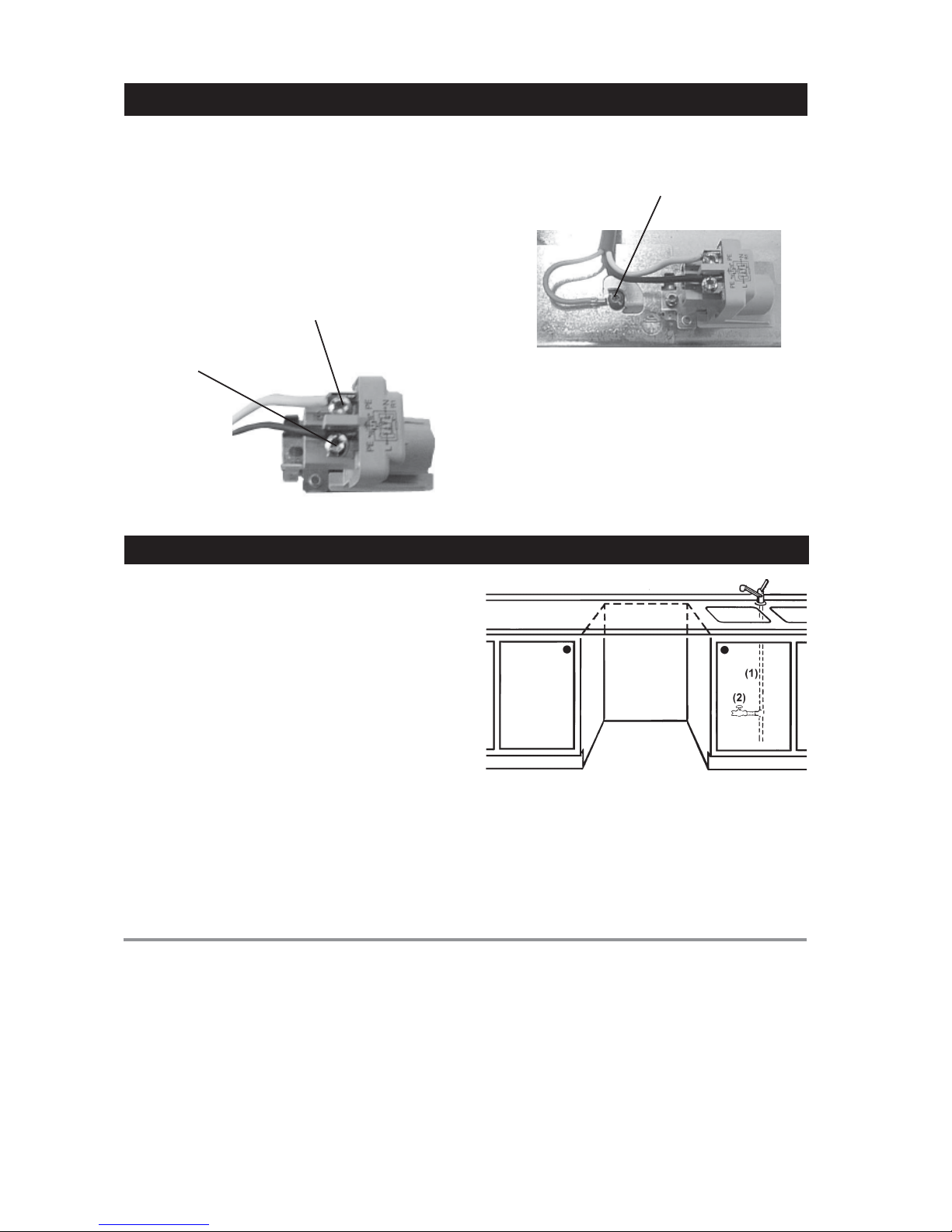
This unit must be grounded to operate properly. It must
be connected to a grounded metal, permanent wiring
system, or an equipment-grounding conductor must
be run with the circuit conductors and connected to the
equipment-grounding terminal or lead of the appliance.
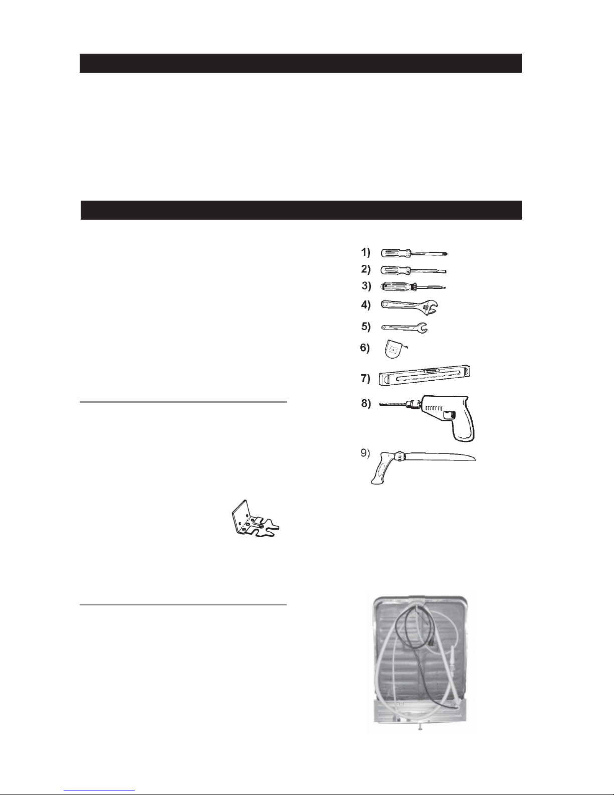
NOTE: Access holes should be 1-1/2” to 2” (38 mm
to 50 mm) in diameter with no sharp edges.
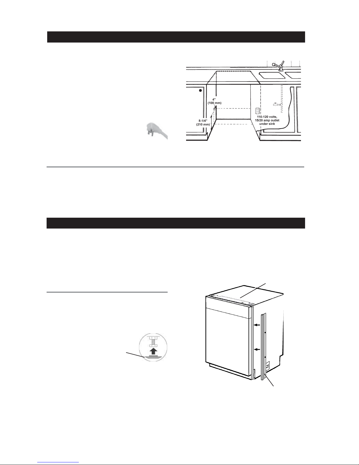
The dishwasher comes with an electrical
cord for 110-120 volts, 15/20 amp
supplied. This cord should be plugged into
the 110-120 volt outlet under the sink.
If the cord is not long enough, or if a hard-
wire installation is needed, follow
instructions on page 8.
GRGR
GRGR
GROUNDING INSTROUNDING INSTR
OUNDING INSTROUNDING INSTR
OUNDING INSTRUCTIONSUCTIONS
UCTIONSUCTIONS
UCTIONS Damage to the dishwasher could occur if it is not
properly grounded.
WARNING!
Make sure the water supply line,
drain line and branch circuit wiring do not touch
any exposed terminals of dishwasher wiring.
At this point the styrofoam, plastic wrap, and the wood
pallet (base) should be removed from the dishwasher.
Now is an excellent time to inspect for any shipping
damage. Should you find any damage, you should
report it to your dealer or builder immediately.
Be sure to remove the toe kick and toe kick insulation
which are on top of the dishwasher.
SLIDES FOR LEGSSLIDES FOR LEGS
SLIDES FOR LEGS
The unit comes with white plastic slides for the legs to
protect the kitchen floor from being damaged when you
slide the unit into place. The slides simply snap onto
the bottom of the legs.
ELECTRICAL CONNECTIONSELECTRICAL CONNECTIONS
ELECTRICAL CONNECTIONS
PREPPREP
PREPPREP
PREPARINGARING
ARINGARING
ARING THE DISHWTHE DISHW
THE DISHWTHE DISHW
THE DISHWASHER FOR INSTASHER FOR INST
ASHER FOR INSTASHER FOR INST
ASHER FOR INSTALLAALLA
ALLAALLA
ALLATIONTION
TIONTION
TION
WARNING!
Do not use an extension cord for this appliance.
THE FILL STRIPSTHE FILL STRIPS
THE FILL STRIPS
All Asko Tall Tank dishwashers come with color-coded
fill strips to finish out the installation.
Fill Strip
NOTE: If the cabinet opening is European measure-
ment (23-1/2 inches [597 mm]), remove the fill
strips to fit the dishwasher into the opening.
Protective slides for legs simply
snap onto the bottom of the legs.
Fill Strip
(Noton allmodels)

Page7
WARNING!
Make sure you put the protective slides on the legs to
prevent damaging the floor when you slide the unit
into place (see page 6).
1. Position the machine in front of the cabinet
opening.
2. Make the height adjustment while the dishwasher
is in front of the opening.
3. Pull out the drain hose to ensure there are no sharp
bends.
4. Start to feed water and drain lines and electric cord
(if necessary) into the access hole in the cabinet.
5. Gently slide the unit into the dishwasher opening.
As you do this, feed the drain line and inlet hose
into the access hole in the side of the cabinet.
WARNING!
Be careful of sharp edges.
As you slide the unit into place, feed the drain line and
inlet hose into the access hole in the side of the cabinet.
MOMO
MOMO
MOVINGVING
VINGVING
VING THE MATHE MA
THE MATHE MA
THE MACHINE INTCHINE INT
CHINE INTCHINE INT
CHINE INTO PLAO PLA
O PLAO PLA
O PLACECE
CECE
CE

Page8
TESTING FOR LEAKSTESTING FOR LEAKS
TESTING FOR LEAKS
1. Turn on the water supply and check for leaks.
2. Turn the power on at breaker/fuse box and test the
dishwasher operation by running a Rinse cycle.
(This should take about four minutes.)
3. Turn off the electrical power and check for leaks
In order to prevent heat damage to the inlet valve, all
solder connections must be made before the water
supply line is connected.
Flush the water supply line prior to connecting it to the
water fill tube.
The unit has a float switch in the base pan to protect
against flooding. If the inlet valve connection is not
seated properly, water may leak into the base pan and
activate the float switch.
It is important that the water supply line and the shut-off
valve have a sufficient flow volume. At last 3 gallons (12
liters) per minute must be able to pass through the
line. The water pressure should be 18-176 psi.
Be sure to run the PEX tubing through the hole
to sink compartment before moving the
dishwasher into position.
NOTE:
under the dishwasher and sink.
4. Make sure that no kinks have developed in the drain
lines.
If there are no leaks and the dishwasher seems to be
working properly, continue with the installation.
CONNECTINGCONNECTING
CONNECTING THETHE
THETHE
THE WW
WW
WAA
AA
ATER SUPPLTER SUPPL
TER SUPPLTER SUPPL
TER SUPPLYY
YY
Y
(1) Water supply
(2) Water supply valve
(not supplied)
1. Connect supply cable with
a UL-listed strain relief
bushing (if nonmetallic
cable is to be used).
2. Connect branch circuit
whitelead to N leadon filter.
3. Connect branch circuit
blacklead to L leadon filter.
WARNING!
Before starting this procedure, be sure
the power is turned off at the breaker/fuse box.
CONNECTING THE ELECTRIC CABLECONNECTING THE ELECTRIC CABLE
CONNECTING THE ELECTRIC CABLE
If the cord is not long enough, or if a hard-wire
installation is needed, follow the steps below to
complete the electrical connection. 4. Connect ground wire to ground connection screw
on the bottom.
NOTE: When doing a hard-wire installation, you must
remove the supplied power cord.

Page9
Now that all the connections are made and the machine
is in place under the cabinet, you should make the final
height adjustment.
1. You should set the
rear foot first. To do
this, use a
screwdriver to rotate
the adjusting screw
on the bottom front of
the machine. Turn the
screw clockwise to
raise the foot and
counterclockwise to lower it.
2. Using a 1/2” (12 mm) wrench, adjust the locking
nuts until the machine is
level. (The machine may
have an inclination of 1/4"
maximum without affecting
its performance.)
3. When the feet are properly adjusted, tighten the
locking nuts to the base pan.
Once you have the toe kick bracket in place, you can
install the toe kick, as follows:
1. Lay the insulation on the back side of the toe kick to
make sure it fits properly.
2. Peel the adhesive protection strip off the insulation
and press it firmly to the back side of the toe kick,
making sure you don’t cover any slots on the toe
kick.
3. Positioning the notches on the toe kick at the edge
of the access panel, slide the toe kick up behind
the access panel then let it slide to the floor.
4. Adjust the toe kick depth.
INSTINST
INSTINST
INSTALLINGALLING
ALLINGALLING
ALLING THETHE
THETHE
THE TT
TT
TOE KICKOE KICK
OE KICKOE KICK
OE KICK
It’s necessary to fasten the dishwasher to the cabinet
so it won’t tilt when the door is opened or if something
heavy is placed on the door. Use only screws provided
with the machine.
1. Use option A for U.S. or European standard
installations. Use option B only for European
standard installations.
2. Cover the screw heads with the
plastic plugs provided with the
machine.
3. When the machine is properly
attached, check that the feet are
tight against the floor and that the
machine is level.
FASTENING THE DISHWASHER TO THE CABINETFASTENING THE DISHWASHER TO THE CABINET
FASTENING THE DISHWASHER TO THE CABINET
NOTE: When it is not possible to attach the dishwasher
to the cabinet, you should install tip guards.
(See “Tip Guards” on page 2.)
Mounting
Screws
ADJUSTING THE LEVELING LEGSADJUSTING THE LEVELING LEGS
ADJUSTING THE LEVELING LEGS
SETTINGSETTING
SETTINGSETTING
SETTING THETHE
THETHE
THE TT
TT
TOE KICKOE KICK
OE KICKOE KICK
OE KICK
DEPTHDEPTH
DEPTHDEPTH
DEPTH
1. Press the grey catches
toward each other to
release the bracket.
2. Pull out the holders as
far as required.
3. Press in the catches so
that they lock the
brackets in place.
4. Hang the toe kick onto the holders by inserting it
into the grooves.
AA
BB

Page10
FITTING THEFITTING THE
FITTING THE D3252XLFI, D3532XLFI AND D3532XLFIWSD3252XLFI, D3532XLFI AND D3532XLFIWS
D3252XLFI, D3532XLFI AND D3532XLFIWSD3252XLFI, D3532XLFI AND D3532XLFIWS
D3252XLFI, D3532XLFI AND D3532XLFIWS
CUSTCUST
CUSTCUST
CUSTOM DOOROM DOOR
OM DOOROM DOOR
OM DOOR PP
PP
P
ANELANEL
ANELANEL
ANEL
The D3252XLFI, D3532XLFI, and D3532XLFIWS can
only be installed with a fully-integrated custom door
panel that extends from the toe kick to the counter top.
The unit comes with everything needed to make
installing the door panel easy. The door is predrilled for
the panel’s mounting screws.
Width: 23-1/2” (597 mm)
Height: 30 1/8" (765 mm)
(Measured from the top of the panel to the lower edge of
the kitchen cabinet.)
Thickness: 3/4” (19 mm) max
Weight: Up to 22 lb.
Fit the handle onto the panel according to the manufacturer’s instructions.
(NOTE: A handle should be used rather than a knob, because a knob
does not provide enough grip.)
NOTE: Before fitting the custom panel, the dishwasher must be installed
underneath the cabinet. After you’ve made the required measurements,
pull the machine out again to install the panel.
NOTE: Specifications subject to change without notice.
PREPPREP
PREPPREP
PREPARINGARING
ARINGARING
ARING THETHE
THETHE
THE WW
WW
WOOD POOD P
OOD POOD P
OOD PANEL FOR MOUNTINGANEL FOR MOUNTING
ANEL FOR MOUNTINGANEL FOR MOUNTING
ANEL FOR MOUNTING
ITEMS PRITEMS PR
ITEMS PRITEMS PR
ITEMS PROO
OO
OVIDEDVIDED
VIDEDVIDED
VIDED WITHWITH
WITHWITH
WITH THETHE
THETHE
THE
UNITUNIT
UNITUNIT
UNIT
♦Two 3/8” screws
♦Four 1-3/4” screws
CUSTCUST
CUSTCUST
CUSTOM POM P
OM POM P
OM PANEL DIMENSIONSANEL DIMENSIONS
ANEL DIMENSIONSANEL DIMENSIONS
ANEL DIMENSIONS
1. Lay the template edge-to-edge with the lower edge of the dishwasher
door or the adjusting frame. The broken line on the template must
pass through the center of the keyholes on the door.
2. Using a pen or screw, punch holes in the template where the
keyholes are.
3. Lay the template on the back of the wood panel, edge-to-edge with
the rear of the lower edge and the left edge of the panel.
4. Mark the location of the hole on the panel.
5. Turn the template over and lay it on the right side of the wood panel
and mark the location of the second hole.
6. Screw the short screws into the markings on the wood panel, letting
them project by about 1/16".
.
30 1/8
"
765 mm

Page11
4-inc4-inc
4-inc4-inc
4-inchh
hh
h TT
TT
Toe Kicoe Kic
oe Kicoe Kic
oe Kick Installak Installa
k Installak Installa
k Installationstions
tionstions
tions
Custom panel extends to cabinet top
One installation option for a 4” toe kick is to extend the
custom panel to the cabinet top (as illustrated below).
D3252XLFI,D3252XLFI,
D3252XLFI, D3532XLFI,D3532XLFI,
D3532XLFI,D3532XLFI,
D3532XLFI,
AND D3532XLFIWS CUSTAND D3532XLFIWS CUST
AND D3532XLFIWS CUSTOM POM P
OM POM P
OM PANELANEL
ANELANEL
ANEL
INSTINST
INSTINST
INSTALLAALLA
ALLAALLA
ALLATION OPTIONSTION OPTIONS
TION OPTIONSTION OPTIONS
TION OPTIONS
6-inc6-inc
6-inc6-inc
6-inchh
hh
h TT
TT
Toe Kicoe Kic
oe Kicoe Kic
oe Kick Installak Installa
k Installak Installa
k Installationstions
tionstions
tions
XL units are not designed to accomodate a 6 inch
toe kick installation. If you need a 6 inch toe kick
installation, you should install anAsko standard
tankdishwashermodel D3122 or D3252FI.
One-Piece CustomOne-Piece Custom
One-Piece Custom
Door PanelDoor Panel
Door Panel
A one-piece custom door panel
with a curved handle is now
available for the FI dishwashers.
This door is available in stainless
steel (as shown), black, and white.
To order this door panel, contact
your dealer.
These doors are designed for 4” toe
kick installations.
Panel extends from toe kick to cabinet top
4-inch toe kick
30 1/8"
765 mm
23-1/2"
597 mm
ADJUSTING THE DOOR SPRINGSADJUSTING THE DOOR SPRINGS
ADJUSTING THE DOOR SPRINGS
After you install the custom panel,
make sure the door stays in place at
any angle. If it tends to fall down, pull
out the machine and tension the door
springs on the sides of the machine
by moving them one hole farther back
or by twisting the spring to make it
shorter. If that doesn’t resolve the
problem, you may need to purchase
the heavy-duty door springs (part
number 8076163-77).
1. Locate the screw heads in the keyholes and push the wood panel to
one side and align with the door. (Figure 5)
2. Clamp the wood panel to the dishwasher door to keep it securely in
place.
3. Open the dishwasher door and screw the wood panel into position
with the four long screws, two on either side. (Figure 6)
.
MOUNTINGMOUNTING
MOUNTINGMOUNTING
MOUNTING THETHE
THETHE
THE WW
WW
WOOD POOD P
OOD POOD P
OOD PANELANEL
ANELANEL
ANEL

Page12
AA
AA
A
Access holes 3
CC
CC
C
Cabinet,fastening unit to 9
Cabinetopening dimensions 3
Connecting to water supply 9
Cornerinstallation 4
Cosmetic damage 2
DD
DD
D
Dimensions, unit 3
Doorpanels, fully-integrated 11
Door springs, adjusting 10
Drain connections 4
EE
EE
E
Electrical cable connection 8
Electrical connections 7
European installations 3
FF
FF
F
Fastening unit to cabinet 9
Fill strips 6
Fully-integrateddoor panels 10
GG
GG
G
Groundinginstructions 6
HH
HH
H
Heating element 2
High loop 5
Hot water supply 4
LL
LL
L
Leaks, testing for 8
Levelinglegs, adjusting 9
MM
MM
M
Materials 2
Moving unit into place 7
PP
PP
P
Panels,fully-integrated 11
Placing the unit 7
Power 2
SS
SS
S
Slides for rear legs 6
TT
TT
T
Technical data 2
Tip guards 2
installing 4
Toe kick
installation options on FI units 11
installing 9
Tools 2
UU
UU
U
Unit dimensions 3
WW
WW
W
Water connection 9
Waterflow volume 4
Water pressure 2
INDEXINDEX
INDEXINDEX
INDEX
Art. No 8075801 rev 03
This manual suits for next models
2
Table of contents
Other Asko Dishwasher manuals

Asko
Asko D3251HDSS User manual

Asko
Asko DSD644GXXL User manual

Asko
Asko D5644 Assembly instructions

Asko
Asko D5636XLHS/PH User manual

Asko
Asko DFI654BXXL User manual

Asko
Asko DBI344ID.W User manual

Asko
Asko DOD651PHXXLS User manual

Asko
Asko D5894XXLFI User manual

Asko
Asko D3122 Owner's manual

Asko
Asko D3250 Owner's manual