10
COMPONENT INFORMATION
Flow meter
The flow meter is fitted in the air gap. The
flow meter is used to control the water intake
so that the right volume is taken in regard-
less of the water pressure. It is even possible
to program the machine for time-controlled
water intake.
The flow meter comprises an impeller with two
magnets that is driven by the water flow. On the
outside, on the flow meter housing, is a sensor,
a reed switch, which closes each time the mag-
nets pass. The number of pulses from the sensor
is proportional to the volume of the flowing
water. A minimum water flow of 2 litres/minute
is required for the flow meter to operate. If
the necessary level is not reached within one
minute, the program stops.
Output signal: 220 pulses per litre.
Circulation pump
The circulation pump comprises an asynchro-
nous motor, with a pump component and a
condenser.
Spray arm diverter
Certain machines are fitted with a spray arm
diverter. The spray arm diverter comprises a
synchronous motor that drives a disc valve
via a gearbox. The disc distributes different
4.2Componentsandfunctiondescription
Here we present the functions and specifica-
tions of the various electrical components.
Some components are only found in high-end
machines or in particular markets.
Inlet valve
Both single and safety inlet valves are used.
The valve contains a filter to stop particles then
a flow limiter to limit the flow to a maximum of
4 l/min. The valve opens when the water pres-
sure exceeds 0.3 bar and provides full flow at
about 2 bar.
Safety valve
The safety valve has two independent valve
seats, each controlled by a separate elec-
tromagnet. The valve seats are connected
in series. This doubles the safety factor. The
electromagnets are also connected in series
(electrically), which means each magnet’s
rated voltage is half the mains voltage (e.g., a
230 V valve = 2 x 115 V coils)
Single valve
The single valve comprises an electromagnet
and a valve seat.
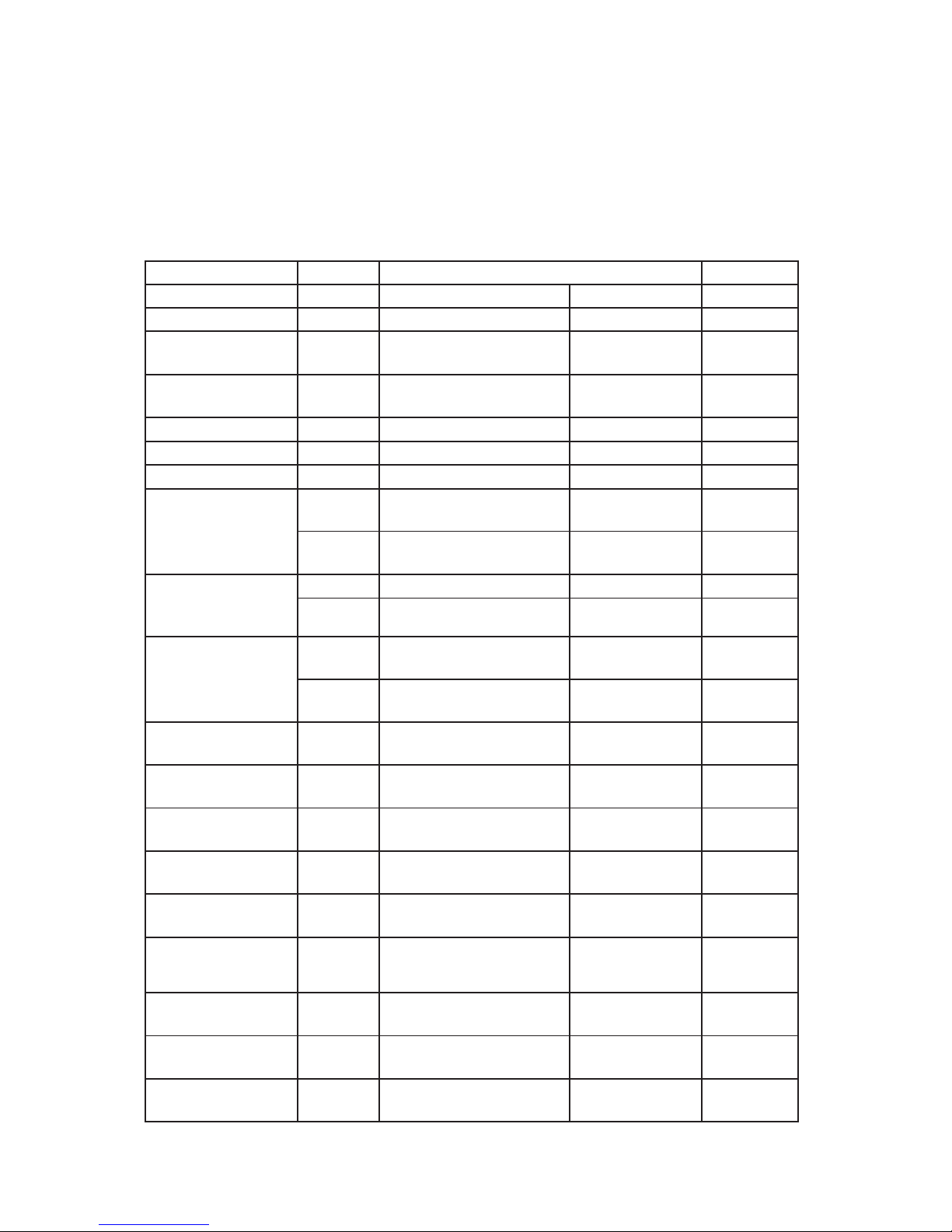
Article no. Position Component
8078090*
8078090 *
Softener salt water
valve 220/240 V
3 kohm
Softener mixer valve
220/240 V
2.33 kohm
8078302*
8078302*
Softener salt water
valve 120 V
0.65 kohm
Softener mixer valve
120 V
0.65 kohm
8073830 Halogen bulb 5 W/12 V <10 kohm
8052778 Vax motor 1.1 kohm
8073850 Fan motor 230 V 0,44 kohm
8073848 Fan motor 120 V 0.18 kohm
* The number is for a complete water softener; replacement salt and mixer valves are not
available separately.