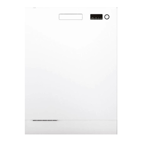
Asko D1996FI User manual

Model D1996FI, SS, and HNDL
(DW 95FI)
Page
Date
2000-06 1
INDEX
D1996FI, SS, and HNDL DISHWASHER
(DW95FI)
ll PROGRAMS 2
ll ELECTRICAL FUNCTIONS 5
ll PART NUMBER SUFFIX DEFINITIONS 7
ll SPARE PARTS LIST
♦♦ 1996FI Casing and related parts 8
♦♦ 1996SS & HNDL Casing and related parts 10
♦♦ Container and related parts 12
♦♦ 1996FI Door 14
♦♦ 1996SS & HNDL Door 16
♦♦ 1996FI Control Panel 18
♦♦ 1996SS Control Panel 20
♦♦ 1996HNDL Control Panel 22
♦♦ Dishwashing system 24
♦♦ Interior light 26
ll WIRING DIAGRAM 28
ll TIMER DIAGRAM 29
ll SERVICE INFORMATION
♦♦ Air duct nozzle 30
♦♦ Door springs 31
♦♦ Water level 32
♦♦ Door lock 33
♦♦ Control unit failure analysis 34

Model D1996FI, SS, and HNDL
(DW 95FI)
Date
2000-06 Page
2
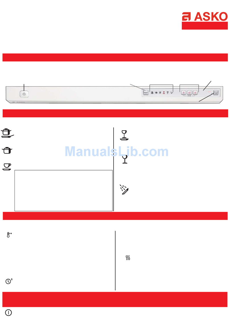
PROGRAMS
PROGRAMS
PROGRAM DEFINITION
Pots and pans/Sani Two prewashes, main wash, three rinses* and drying.
Normal Two prewashes, main wash, two rinses* and drying.
Quick Short prewash, main wash, two rinses, heated drying.
Rinse & Hold One rinse. If Heat fan dry is selected, the heating element will activate.
Rinse: 131°F (55°C). Drying: 158°F (70°C)
*The Pots and Pans/Sani and Normal programs can be programmed for an extra rinse (see page
3). In that case, the temperatures for the next-to-last rinse would be the household water
temperature and the final rinse would be the last rinse temperature indicated in the table below.
OPTIONS
Economy Lowers the water temperature in the main wash to 122°F (50°C) and extends the
wash time in the main wash by 15 minutes.
Temp selection Lets you select high or low water temperatures for the wash programs (except
Rinse). (See the table below.) The indicator light glows when it’s on the High setting
and remains off when set on Low.
Heat Fan Dry Pressing this touchpad activates the heating element along with the turbo fan for
12 minutes after the final rinse. (158° F/70° C)
Delay Lets you delay running the dishwasher for five hours. After making your selections, press
the Delayed Start touchpad then press Start and close the door. The machine will start in
5hours.
Start/Stop Press this touchpad to Start or Stop the machine. To interrupt a program, hold this
touchpad down for three seconds.
Wash 1st 2nd Main 1st 2nd 3rd
Program Temp Prewash Prewash Wash Rinse Rinse Rinse
Pots & Low 113°F House 131°F House House 131°F
Pans/Sani (45°C) (55°C) (55°C)
High 113°F House 158°F House House 149°F
(45°C) (70°C) (65°C)
Normal Low 86°F House 131°F House 131°F n/a
(30°C) (55°C) (55°C)
High 86°F House 149°F House 149°F n/a
(°30C) (65°C) (65°C)
Quick Low House n/a 113°F House 113°F n/a
(45°C) (45°C)
High House n/a 131°F House 131°F n/a
(55°C) (55°C)
WASH PROGRAM TEMPERATURES

Model D1996FI, SS, and HNDL
(DW 95FI)
Page
Date
2000-06 3
PROGRAMS
EXTENDING FAN COOLING TIME
To extend the fan cooling time, press S1 five times then press one of the following:
S5 for 30 extra minutes
S4 for normal fan cooling time
SETTING AN EXTRA RINSE
To add an extra rinse to the Pots and Pans and Normal wash programs, press S2 five times then
press one of the following:
S5 for an extra rinse
S4 for the normal number of rinses
SETTING CHILD-SAFE START FUNCTION
The start function can be reprogrammed so that the button must be pressed in for 3 seconds to start the
programs. To do so, press S4 five times then press one of the following:
S5 to get a prolonged start function or
S4 to get a normal start function
SETTING PUMP-OUT TIME
If it's necessary to reprogram the pump-out time, you can do so bypressing S3 five times then pressing
one of the following:
Press: to get an outlet time of:
S3 20 seconds
S4 25 seconds (factory setting)
S5 35 seconds
S6 45 seconds
S7 85 seconds
SETTING INLET TIME
You can reprogram the inlet time on level controlled and time controlled inlets. To do this, press S5 five
times then press one of the following:
Press: to get an inlet time of:
S3 45 seconds (factory setting)
S4 56 seconds
S5 68 seconds
S6 90 seconds
S7 113 seconds
S8 180 seconds
S = Pushbutton switch L = Indicator light

Model D1996FI, SS, and HNDL
(DW 95FI)
Date
2000-06 Page
4
PROGRAMS
FAULT INDICATIONS
Blinking lights indicate a machine fault.
Blinking Lights Problem
L3 and L7 Heating element
L1–L8 Overfill
L4 and L5 Thermistor fault (heater control)
L1–L4 Water inlet
FAULT-TRACING PROGRAM
The functions of the electrical components can be tested by pressing S6 five times
then pressing one of the following:
S2 for inlet valve 2
S3 for inlet valve 1
S4 for combi-dispenser
S5 for heating element
S6 for the circulation pump
S7 for the outlet pump
S8 for fan motor and wax motor
Stop the fault-tracing program by pressing one of the program buttons for 3 seconds.
LINKS ON THE PROCESSOR BOARD
(for program variations)
These diodes should be cut for proper U.S.iInstallation:
Link 953: D1796 processor board layout
Link USA: USA processor board layout
S = Pushbutton switch L = Indicator light

Model D1996FI, SS, and HNDL
(DW 95FI)
Page
Date
2000-06 5
CONTROL PANEL (see page 15)
The control panel contains a microprocessor for control of programs, circulation pump, inlet valves, etc.
It also allows for custom settings of programs (see page 3).
CIRCULATION PUMP/MOTOR (see page 17)
The circulation pump/motor consists of a synchronous motor and pump, constructed in an integrated
unit. A 16 µF capacitor is fitted to the circulation motor/pump.
OUTLET PUMP (see page 17)
The outlet pump consists of a synchronous motor and pump, constructed in an integrated unit.
INLET VALVE (see page 17)
A single-unit type: A solenoid and valve seat.
HEATING ELEMENT (see page 11)
1400 Watt
THERMISTOR (see page 11)
The thermistor controls the water temperature within +/-1°C (2.5°F) to give the required temperature.
The heater will be disconnected if the thermistor is short-circuited or loosened from the circuit board and
the fault code "F3" displays in the LED window. The normal resistance of the thermistor is between 25
and 15K ohm at 68°F (20°C) or 86°F (30°C) alternately.
OVERHEAT PROTECTION (see page 11)
The thermostat has a switch-off function at 190° F (88°C) that prevents the heating element from staying
on if the control unit or the timer should fail.
DOOR SWITCH (see page 17)
A microswitch senses that the door has been opened. This interrupts the program and cuts the power to
all control components (motor, valves, etc.).
LEVEL SWITCH (PRESSURE SWITCH) (see page 11)
This switch provides protection against overfilling by interrupting the power to the inlet valve and starting
the outlet pump. If the water level has not dropped within 30 seconds or if overfill has occurred twice
during the same program, the program will be terminated and a fault code displays. The overfill protection
operates during all programs, including fault-tracing, even if the microprocessor is faulty.
OVERFILL SWITCH (see page 11)
A float in the base pan influences a microswitch that disconnects the inlet valve and starts the outlet
pump.
COMBI-DISPENSER (see page 13)
The combi-dispenser dispenses both detergent and rinse aid. The dispenser has an adjustable volume
chamber for setting the desired amount of rinse aid.
TURBO FAN (see page 13)
The turbo fan evacuates the moist air from the machine during the drying phase of the program. The fan
system consists of a fan motor that runs a two-part impeller. Dry, cool air is pulled in from the door into
one of the impeller halves. A wax motor opens a damper and the moist air is pulled into the other part of
the impeller. The dry, cool air and warm, moist air mix and condense in the condensation chamber. The
condensed moisture then drains through the channel to the lower sump area. Dry air is then vented out
through a channel below the outer door.
ELECTRICAL FUNCTIONS

Model D1996FI, SS, and HNDL
(DW 95FI)
Date
2000-06 Page
6
ELECTRICAL FUNCTIONS
ELECTRICAL SUPPLY
The machines are wired for connection to a single-phase, 120V, 15A supply, with a heater power of
1400W, giving a total power requirement of 1600W.
VALUES FOR WIRING DIAGRAMS
Resistance values at 68° F (+/-5°F), 20° C (+/-3°C)
(Values within +/- 10% is normal.)
AP Drain pump 120V, 60 Hz, 25.5 ohm
BB Illumination switch
BE Internal Illlumination 120V, 51 ohm
CP Main pump 120 V, 60 Hz, Main = 10.5 ohm, Aux = 14.5 ohm
KD Combi-dispenser 120 V, 0.31 ohm
EL Heating element 120 V, 1400 W, 10 ohm
FFilter 680 K ohm (1-2,3-4)
IV Inlet valve 120 V, 9.93K ohm
FL Fan 120 V, 0.25K ohm
LB Door switch
LU Door
NLevel switch
PControl unit
TThermostat 19–25 K ohm
TB Pushbutton switch
TTE Temp. thermistor 18–25 K ohm
WAX Wax motor 1.5–3.0 K ohm
VMG Rinse ag sensor
OB Overflow switch

Model D1996FI, SS, and HNDL
(DW 95FI)
Page
Date
2000-06 7
PART NUMBER SUFFIX DEFINITIONS
The lists below define the meanings of the dashed numbers or letters following a part number:
Colors:
-0 White
-29 Black, bright
-33 Black
-36 Dark grey
-49 Helios grey
-69 black, metallic
-77 grey
-81 metallic
-95 Stainless Steel
Note: Not all colors are available for all parts.
Doors
-M for units with fan
-P for integrated units
-R for decor frames, long devision
-S for decor frames, short devision
-T for decor frames with adjustable lower part

Model D1996FI, SS, and HNDL
(DW 95FI)
Date
2000-06 Page
8
1996FI CASING AND RELATED PARTS
Model D1796FI
(DW 95FI)
Date
2000-06 Page
8
CASING AND RELATED PARTS

Model D1996FI, SS, and HNDL
(DW 95FI)
Page
DescriptionFig.PartNo. Notes
Date
2000-06
Qty
9
1996FI CASING AND RELATED PARTS
1 1 80 583 53 Soundinsulation
2 1 80 600 41 Soundinsulationprofile
3 1 80 575 26 Guardplate
489 003 52 Screw RTS ST 4.2x13
4 1 80 600 87 Felt, kick plate
5 1 80 575 28- Kick plate, low -0, -29
180 575 29- Kickplate,high -0, -29
289 009 44- Screw, kick plate -0, -29
9 1 80 584 86 Drip protection for guard plate
10 280 575 49 Bracket, kick plate
11 280 575 50 Spring, kick plate
289 003 27 Screw RTS ST 4.2x13 FZB T20

Model D1996FI, SS, and HNDL
(DW 95FI)
Date
2000-06 Page
10
1996SS and HNDL CASING AND RELATED PARTS
9
11
1
2
3
4
5
6
7
8
10

Model D1996FI, SS, and HNDL
(DW 95FI)
Page
DescriptionFig.PartNo. Notes
Date
2000-06
Qty
11
1996SS AND HNDL CASING AND RELATED PARTS
1 1 80 583 53 Soundinsulation
2 1 80 600 41 Soundinsulationprofile
3 1 80 575 26 Guardplate
489 003 52 Screw RTS ST 4.2x13
4 1 80 707 43 Felt, kick plate
5 1 80 597 58- Kick plate, low -0, -29
289 009 44- Screw, kick plate -0, -29
6 1 80 706 15 Sealing strip
7 1 80 571 00- Lower cover -S-0, -S-29, -95
289 003 52 Screw RTS ST 4.2x13
480 097 69- Plug for decor frame -0, -33
8 1 80 706 12 Soundinsulation
9 1 80 584 86 Drip protection for guard plate
10 280 575 49 Bracket, kick plate
11 280 575 50 Spring, kick plate
289 003 27 Screw RTS ST 4.2x13 FZB T20

Model D1996FI, SS, and HNDL
(DW 95FI)
Date
2000-06 Page
12
CONTAINER AND RELATED PARTS
Model D1796FI
(DW 95FI)
Date
2000-06 Page
8
CASING AND RELATED PARTS

Model D1996FI, SS, and HNDL
(DW 95FI)
Page
DescriptionFig.PartNo. Notes
Date
2000-06
Qty
13
CONTAINER AND RELATED PARTS
2 1 80 600 65 Sealing strip, left
180 600 66 Sealingstrip,right
280 600 38 Insulation,bottomouter
3 1 80 574 89 Tub seal
4 2 80 579 78- Ball catch -77
5 2 80 586 38- Ballbearingholder,guiderail -77
6 8 80 579 77 Ballbearings
7 2 80 579 79- Basket stop -77
8 2 80 570 52 Guiderail
9 1 80 600 33 Soundinsulation
10 489 011 10 Screw + O-ring A2-M6x12 T30
11 180 570 77 Heating element 1400 W 120 V
180 602 58 Cableholder For heating
280 023 70 Protection collar, heating
12 180 584 95
13 280 583 52 Soundinsulation
14 180 701 42 Cableholder
15 180 025 79 Thermostat Overheat protection
16 180 597 61- Strip side, left -0, -29, -95, for D1996SS & HNDL
180 59762- Strip side, right -0, -29, -95, for D1996SS & HNDL
489 006 46 Screw A4RTS 4.2x13 T20
289 003 52 Screw RTS ST 4.2x13
17 280 706 14 Sealing strip for D1996SS & HNDL
18 180 575 23 Base pan
289 011 04 Screw A2-MRT-TT 4x8 T20
19 280 584 91- Doorsprings compl. -77, for D1996SS & D1996HNDL
280 602 32 Door springs compl., integrated -77, D1996FI
280 713 23- Door springs compl., integrated -77, heavy-duty for D1996FI (optional)
20 180 704 95 Mount,inletvalve
289 003 27 Screw RTS ST 4.2 x 13 FZB T20
21 180 602 55 Mount, electrical connection
22 180 599 91 Cableholder
23 180 069 48 Grommet
24 180 585 58 RFIfilter
25 180 502 51 Terminal block 3-pole
189 003 57 Screw, terminal block RTS ST 4.2x25 FZB T20
189 021 31 Screw, grounding terminal bl. MRT-TT 4x6 FZB T20
189 014 13 Washer AZ4.3FZB
26 480 721 19 Reinforcement washer
27 480 570 62 Levelingleg M10x100, 8.8 FZB
28 489 011 56 Nut M6M10 BH8 FZB
29 280 519 57 Slide foot, rear only

Model D1996FI, SS, and HNDL
(DW 95FI)
Date
2000-06 Page
14
D1996FI DOOR

Model D1996FI, SS, and HNDL
(DW 95FI)
Page
DescriptionFig.PartNo. Notes
Date
2000-06
Qty
15
D1996FI DOOR
1 1 80 600 21 Fan,complete
2 1 80 527 78 Wax motor
3 1 80 585 01 O-ring
4 1 80 579 63- Air channel, turbo dry -S
5 1 80 722 97 Nozzle for air channel (See page 28)
6 1 80 722 98- Strut for nozzle -29
7 1 88 011 20 Innerdoor,compl.
489 021 20 Screw A2-MKFT5x10-TTFZB
8 1 80 579 64 Lock ring, fan casing
9 1 80 584 84 Cover plate, fan
289 020 85 Screw, fan cover plate A2-PTK 40x10 WN1452
10 180 706 79- Combi-dispenser -77
689 020 87 Screw PTK 40x14 WN1452 FZB
180 719 17 Rinse aid cap
180 719 18 Combi-dispenserlid Incl. seal and spring
11 180 575 25 Hinge,left
180 575 24 Hinge,right
280 575 30 Hinge screw
233500262 Nut,hingebearing,locking Locking4BH8FZB
12 280 579 48 Slide washer, hinge bearing
13 180 715 87 Holder, cable harness
189 021 31 Screw, cable harness holder MRT-TT 4x6 FZB T20
14 180 602 54 Door seal, lower L=555 mm
15 180 579 85 Brace stand
289 006 46 Screw, lower stay A4 RTS 4.2x13 T20
18 180 579 86- Outer door -PT-0, PT-29
689 006 46 Screw A4 RTS 4.2x13 T20
289 003 27 Screw, lower stay RTS ST 4,2x13 FZB T20
280 703 50- Plug -0, -33
19 180 702 94 Soundinsulation,short
20 180 703 63 Adjusting frame, complete

Model D1996FI, SS, and HNDL
(DW 95FI)
Date
2000-06 Page
16
D1996SS AND HNDL DOOR

Model D1996FI, SS, and HNDL
(DW 95FI)
Page
DescriptionFig.PartNo. Notes
Date
2000-06
Qty
17
D1996SS AND HNDL DOOR
1 1 80 600 21 Fan,complete
2 1 80 527 78 Wax motor
3 1 80 585 01 O-ring
4 1 80 579 63- Air channel, turbo dry -S
5 1 80 722 97 Nozzle for air channel (See page 28)
6 1 80 722 98- Strut for nozzle -29
7 1 88 011 18 Innerdoor,compl.
489 021 20 Screw A2-MKFT5x10-TTFZB
8 1 80 579 64 Lock ring, fan casing
9 1 80 584 84 Cover plate, fan
289 020 85 Screw, fan cover plate A2-PTK 40x10 WN1452
10 180 706 79- Combi-dispenser -77
689 020 87 Screw PTK 40x14 WN1452 FZB
180 719 17 Rinse aid cap
180 719 18 Combi-dispenserlid Incl. seal and spring
11 180 575 25 Hinge,left
180 575 24 Hinge,right
280 575 30 Hinge screw
233500262 Nut,hingebearing,locking Locking4BH8FZB
12 280 579 48 Slide washer, hinge bearing
13 180 715 87 Holder, cable harness
189 021 31 Screw, cable harness holder MRT-TT 4x6 FZB T20
14 180 602 54 Door seal lower L=555 mm
15 180 579 85 Brace stand
289 006 46 Screw, lower stay A4 RTS 4.2x13 T20
16 180 579 86- Outer door -PT-0, PT-29
689 006 46 Screw A4 RTS 4.2x13 T20
289 003 27 Screw, lower stay RTS ST 4,2x13 FZB T20
280 561 17 Screw -29
680 097 69- Plug -0, -33
17 180 702 94 Soundinsulation,short

Model D1996FI, SS, and HNDL
(DW 95FI)
Date
2000-06 Page
18
1996FI CONTROL PANEL

Model D1996FI, SS, and HNDL
(DW 95FI)
Page
DescriptionFig.PartNo. Notes
Date
2000-06
Qty
19
1996FI CONTROL PANEL
1 1 80 708 83- Decor insert -0, Assembly instruction
2 1 80 706 50 Spring
3 1 80 706 44- Pushbotton -0, -33, -81
4 1 80 706 43- Main switch casing -0, -33, -81
5 1 80 575 47 Main switch
6 1 80 710 77 Hose 9x13x295
7 1 80 706 47 Lock casing
8 1 80 706 45- Masking -77
9 1 80 706 48 Lock washer
10 180 706 49 Lock catch
189 011 04 Screw A2-MRT-TT 4x8 T20
11 180 710 49 Protective film
12 188 012 03 Controlunit
180 600 76 Contact cover
289 020 53 Screw PTK 40x45/15 FZB
289 020 87 Screw PTK 40x14 WN1452 FZB
13 180 706 41 Handle
289 020 87 Screw PTK 40x14 WN1452 FZB
14 180 729 40- Decor insert -81
15 180 706 40- Panel -0, -69, -81
289 020 85 Screw A2-PTK 40x10 WN1452
16 180 597 67 Thermistor
17 180 734 64 Cableharness complete
180 730 96 Use and Care Guide

Model D1996FI, SS, and HNDL
(DW 95FI)
Date
2000-06 Page
20
1996SS CONTROL PANEL
1
2
3
4
5
6
7
8
9
10
11
12
13
14
15
17
16
This manual suits for next models
2
Table of contents
Other Asko Dishwasher manuals

Asko
Asko DFI654B.AU User manual

Asko
Asko DW1775 User manual

Asko
Asko D5636XLHS/PH User manual

Asko
Asko DBI664 User manual

Asko
Asko DFI652 User manual

Asko
Asko DBI4448MIB.W/1 User manual

Asko
Asko DFS233IB User manual

Asko
Asko DFS244IB User manual

Asko
Asko DBI663THS User manual

Asko
Asko DBI364ID.W.AU User manual
Popular Dishwasher manuals by other brands

Electrolux
Electrolux ESL 7220RO user manual

Electrolux
Electrolux EIDW6305GB - Semi-Integrated Dishwasher Brochure & specs

GE
GE GSD2030ZWW Dimensions

Bosch
Bosch SGX78B55UC use and care manual

Whirlpool
Whirlpool AGB 372/WP Instructions for installation, use and maintenance

Summit
Summit DW-2432 Dimensional drawing