manuals.online logo
Brands
  1. Home
  2. •
  3. Brands
  4. •
  5. ASL INTERCOM
  6. •
  7. Power Supply
  8. •
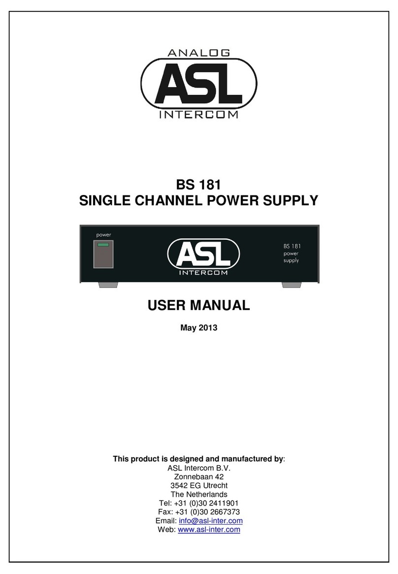
  9. ASL INTERCOM BS 181 User manual

ASL INTERCOM BS 181 User manual

BS 181
SINGLE CHANNEL POWER SUPPLY
QUICK GUIDE
October 2013
This product is designed and manufactured by:
ASL Intercom B.V.
Zonnebaan 42
3542 EG Utrecht
The Netherlands
Tel: +31 (0)30 2411901
Fax: +31 (0)30 2667373
Email: info@asl-inter.com
Web: www.asl-inter.com
PAGE 2
Quick Guide BS 181 / October 2013 © ASL Intercom BV
1.0 GENERAL DESCRIPTION BS 181
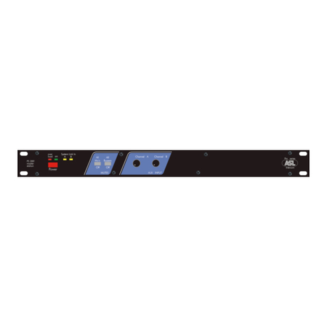
The BS 181 is designed to be a powersupply in an
ASL intercom system. The intercom line power
supply is fully protected against short circuit or
excessive thermal condition and can safely drive
up to fifteen BS15 or BS17 beltpacks operating at
full power.
.
2.0 UNPACKING
The shipping carton contains the parts listed
below.
* The BS 181
* Power cable
* Spare fuses
* Quick Guide
If any are missing contact your dealer.
ASL has taken great care to ensure that this
product reaches you in flawless condition.
After unpacking the unit please inspect for any
physical damage to the unit, and retain the
shipping carton and relevant packing materials for
use should the unit need returning.
If any damage has occurred, please notify your
dealer immediately so that a written claim can be
initiated. Please also refer to the warranty section
of this quick guide.
3.0 WARRANTY
This unit is warranted by ASL Intercom to the
original end-user purchaser against defects in
workmanship and materials in its manufacture for
a period of one year from date of shipment to the
end-user.
Faults arising from misuse, unauthorized
modifications or accidents are not covered by this
warranty. If the unit is faulty it should be sent in its
original packing to the supplier or your local ASL
dealer with shipping prepaid.
A note must be included stating the faults found
and a copy of the original suppliers invoice.
4.0 MAINS POWER & SAFETY EARTH
WARNING: This appliance must be earthed
The BS 181 may be connected to a mains power
outlet (100 - 240 V AC, 50/60 Hz, 60 watts).
The outlet should have a clean earth. Avoid using
mains power outlets which also power dimmer
controlled lighting equipment.
The wires in the mains lead are color coded in
accordance with the following code:
•Green/ yellow:Earth / safety ground
•Blue: Neutral
•Brown: Live
In case the colors of the wires in the mains lead do
not correspond with the colored markings
identifying the terminals in your plug, proceed as
follows:
•The wire which is colored green/yellow
must be connected to the terminal in the
plug which is marked with the letter "E", or
by the earth symbol which or is colored
green.
•The wire which is colored blue must be
connected to the terminal which is marked
with the letter "N" or is colored black.
•The wire which is colored brown must be
connected to the terminal which is marked
with the letter "L" or is colored red.
Safety Earth
For personal safety and proper functioning of
the BS 181, the green-and-yellow wire of the
mains cord must always be connected to the
electrical installation safety earth or ground.
The green-and-yellow wire is internally connected
to all exposed metal surfaces.
Powering up
•Make sure that the mains power switch on
the left side of the front panel is OFF.
•Connect the power cord to the rear of the
station.
•Plug the other end of the power cord into a
properly grounded mains outlet.
•Switch the unit on with the mains power
switch. The green power LED illuminates
indicating the BS 181 is active.
PAGE 3
Quick Guide BS 181 / October 2013 © ASL Intercom BV
5.0 MECHANICAL INSTALLATION
Adequate ventilation must be provided by allowing
sufficient space around the sides and rear of the
unit to ensure free circulation of air.
Forced cooling is not required.
After a period of time the unit will feel warm to the
touch. This is quite normal, and should be no
cause for alarm.
6.0 FRONT PANEL CONTROLS
1 POWER ON/OFF switch
Mains power push button to switch the internal
power supply On or Off
2 POWER LED
This LED illuminates if line power is supplied by
the internal power supply.
7.0 REAR PANEL CONTROLS & CONNECTORS
3 INTERCOM LINE connectors
These two XLR-3 connectors are for connecting
the user stations, via standard microphone cable.
Pin assignments:
Pin 1: 0 V / ground shield
Pin 2: +30 V power wire
Pin 3: audio wire
4 FUSE holder
A fuse protects the BS 181 against severe internal
damage in case of malfunction in the power
section. Disconnected the power cord before
replacing the fuse. Place the correct fuse in the
holder: T 1250 mA (for all mains voltages 100 –
240V AC)
An extra internal fuse is located on the printed
circuit board. Replace this fuse with a 4 A type
only.
5 MAINS INLET
IEC Mains connector.
8.0 TECHNICAL SPECIFICATIONS BS 181
Switch Mode Power Supply
Mains Voltage Range: 100 -240 V AC, 50-60 Hz
Output Voltage: +30 V DC (+/-5%)
Max. Output Power: 45 watts
BS 181 Dimensions & Weight
Width: 176 mm / Height: 42 mm
Depth: 139 mm / Weight: 900 grams
0 dBu defined as 775 mV into open circuit.
ASL reserves the right to alter specifications
without prior notice
For safety instructions and party line concept
& cabling, see the BS 181 User Manual.
Go to www.asl-inter.com, section ‘Support’
and review the referring user manual.
PAGE 4
Quick Guide BS 181 / October 2013 © ASL Intercom BV
9.0 BLOCK DIAGRAM BS 181
10.0 SYSTEM CONFIGURATION

Other manuals for BS 181

2

Other ASL INTERCOM Power Supply manuals

ASL INTERCOM PS 285 User manual

ASL INTERCOM

ASL INTERCOM PS 285 User manual

ASL INTERCOM BS 181 User manual

ASL INTERCOM

ASL INTERCOM BS 181 User manual

ASL INTERCOM BS 181 User manual

ASL INTERCOM

ASL INTERCOM BS 181 User manual

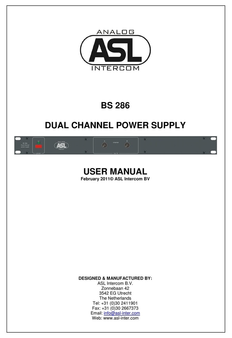
ASL INTERCOM BS 286 User manual

ASL INTERCOM

ASL INTERCOM BS 286 User manual

ASL INTERCOM PS 680 User manual

ASL INTERCOM

ASL INTERCOM PS 680 User manual

ASL INTERCOM PS 289 User manual

ASL INTERCOM

ASL INTERCOM PS 289 User manual

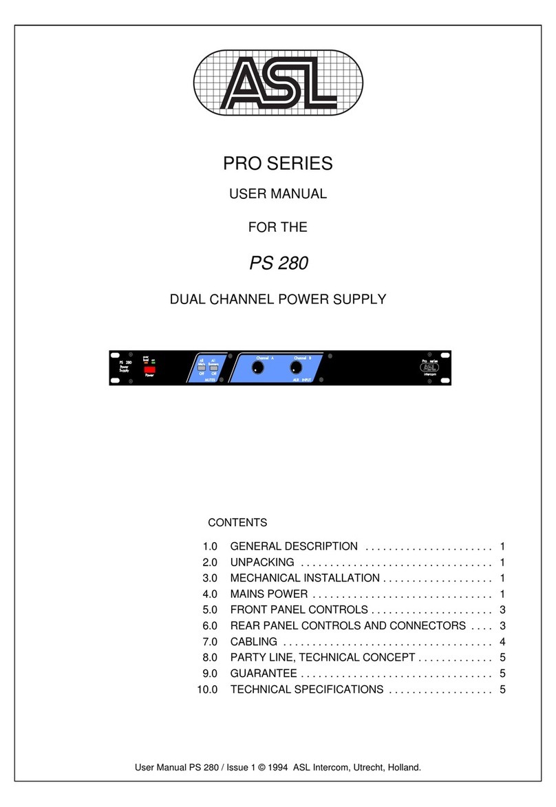
ASL INTERCOM PS 280 User manual

ASL INTERCOM

ASL INTERCOM PS 280 User manual

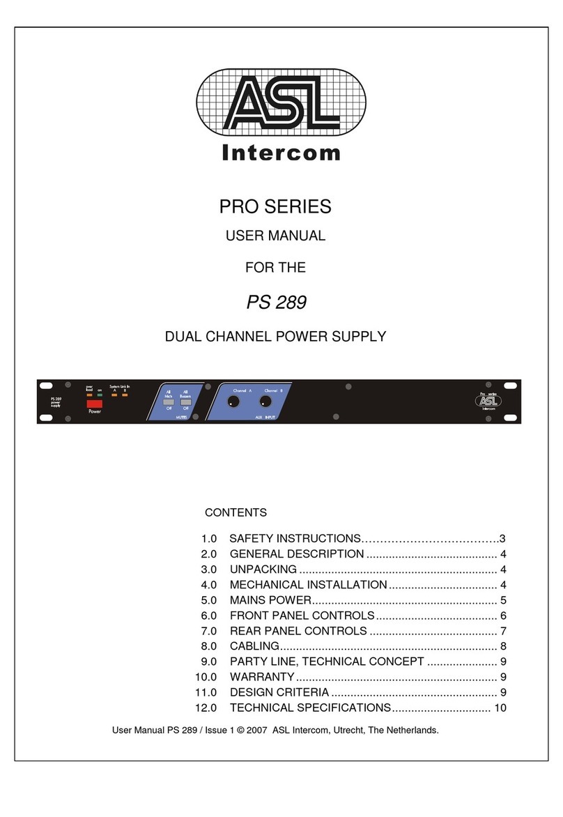
ASL INTERCOM PS 680 User manual

ASL INTERCOM

ASL INTERCOM PS 680 User manual

ASL INTERCOM BS 287 User manual

ASL INTERCOM

ASL INTERCOM BS 287 User manual

ASL INTERCOM PS 680 User manual

ASL INTERCOM

ASL INTERCOM PS 680 User manual

ASL INTERCOM PS 289 User manual

ASL INTERCOM

ASL INTERCOM PS 289 User manual

ASL INTERCOM PS 285 User manual

ASL INTERCOM

ASL INTERCOM PS 285 User manual

ASL INTERCOM DS 85 User manual

ASL INTERCOM

ASL INTERCOM DS 85 User manual

Popular Power Supply manuals by other brands

SIGLENT SPD3303C Series Service manual

SIGLENT

SIGLENT SPD3303C Series Service manual

Allen-Bradley 1606-XLE480FP installation instructions

Allen-Bradley

Allen-Bradley 1606-XLE480FP installation instructions

Fire-Lite Alarms APS-6RF installation instructions

Fire-Lite Alarms

Fire-Lite Alarms APS-6RF installation instructions

Xigmatek VECTOR manual

Xigmatek

Xigmatek VECTOR manual

CCS HLV Series manual

CCS

CCS HLV Series manual

Nemic-Lambda SWS50 Series instruction manual

Nemic-Lambda

Nemic-Lambda SWS50 Series instruction manual

CEA EA3000-3072Wh-1BK Product instruction manual

CEA

CEA EA3000-3072Wh-1BK Product instruction manual

GW Instek GPS-1830 user manual

GW Instek

GW Instek GPS-1830 user manual

NETGEAR APS150W user manual

NETGEAR

NETGEAR APS150W user manual

Faithtech FTP3000 Series user manual

Faithtech

Faithtech FTP3000 Series user manual

Whelen Engineering Company UPS69024 installation guide

Whelen Engineering Company

Whelen Engineering Company UPS69024 installation guide

RTS Systems PS8 Technical manual

RTS Systems

RTS Systems PS8 Technical manual

LiteOn PF-2123-1LDM user guide

LiteOn

LiteOn PF-2123-1LDM user guide

Midas EPS 1200 Operator's manual

Midas

Midas EPS 1200 Operator's manual

StarTech.com ATXPOW500DF Instruction guide

StarTech.com

StarTech.com ATXPOW500DF Instruction guide

Functional Devices PSC100AB10 installation instructions

Functional Devices

Functional Devices PSC100AB10 installation instructions

Veeco MPS-3000 CE Technical manual

Veeco

Veeco MPS-3000 CE Technical manual

Keithley 2260B-30-36 quick start guide

Keithley

Keithley 2260B-30-36 quick start guide

manuals.online logo
manuals.online logoBrands
  • About & Mission
  • Contact us
  • Privacy Policy
  • Terms and Conditions

Copyright 2025 Manuals.Online. All Rights Reserved.