ASL INTERCOM PS 150 User manual

PAGE 2
User Manual PS 150 / May 2011 © ASL Intercom BV
CONTENT OF THIS USER MANUAL
1.0 GENERAL DESCRIPTION ............................ 3
2.0 UNPACKING...................................... 3
3.0 INSTALLATION .................................... 3
4.0 WARRANTY ...................................... 3
5.0 TECHNICAL SPECIFICATIONS PS 150 .................. 3
6.0 FRONT PANEL CONTROLS & CONNECTOR ............. 4
7.0 REAR PANEL CONNECTORS......................... 4
8.0 ESTABLISHING A TELEPHONE CONNECTION............ 5
9.0 THE INTERFACES IN THE PS 150 ..................... 5
10.0 ADJUSTING THE SIDE TONES ........................ 5
11.0 PARTY LINE, TECHNICAL CONCEPT ................... 6
12.0 CABLING ........................................ 6
13.0 EARTHING CONCEPT............................... 7
14.0 BLOCK DIAGRAM PS 150 ........................... 7
15.0 POSSIBLE SYSTEM CONFIGURATION.................. 8

PAGE 3
User Manual PS 150 / May 2011 © ASL Intercom BV
1.0 GENERAL DESCRIPTION
The PS 150 is designed to interface an ASL intercom
system (3-wire party line) to a telephone system
(2-wire). Communication can be achieved between a
telephone line and one or several ASL user stations
or between two ASL intercom systems via a
telephone line.
The unit is a combination of two interfaces.
One interface splits the intercom party line into a
separate audio input and output; the other interface
splits the telephone line into a separate audio input
and output. The inputs and outputs are internally
cross-connected.
Adjustable side tone circuits allow optimizing
input/output separation for the intercom line and for
the telephone line. For a good performance of the
PS 150 the side tones have to adjusted carefully.
The built in test tone generator assists to adjust or
check the side tone settings.
To the PS 150 a telephone set (hereinafter called
“phone”) may be connected to initiate a telephone
connection (dialing a phone number) or to detect an
incoming telephone call (the telephone is ringing).
The PS 150 is powered (30 V DC) via the intercom
party line.
2.0 UNPACKING
The shipping carton contains the parts listed below:
the PS 150
Two telephone cables with RJ-11 connectors
This user manual
If any are missing, contact your dealer.
ASL has taken great care to ensure this product
reaches you in flawless condition.
After unpacking the unit please inspect for any
physical damage to the unit, and retain the shipping
carton and relevant packing materials for use should
the unit need returning.
If any damage has occurred, please notify your
dealer so that a written claim can be initiated. Please
also refer to the warranty section of this manual.
3.0 INSTALLATION
Connecting the PS 150 to the intercom party line:
Connect the intercom party line cable to the
intercom line connector on the rear panel.
Use professional flexible microphone cable with 2
wires and 1 shield only.
The PS 150 is fully protected against wiring
mistakes (reverse power) or short circuit in the
interconnecting microphone cables.
Connecting the PS 150 to the telephone line:
Connect the telephone cable to the RJ-11 connector
on the rear panel.
4.0 WARRANTY
This unit is warranted by ASL Intercom to the
original end-user purchaser against defects in
workmanship and materials in its manufacture for a
period of 12 months from the date of shipment to the
end-user.
Faults arising from misuse, unauthorized
modifications or accidents are not covered by this
warranty. If the unit is faulty, it should be sent in its
original packing to the supplier or your local ASL
dealer, with shipping prepaid. A note must be
included stating the faults found and a copy of the
original suppliers invoice.
5.0 TECHNICAL SPECIFICATIONS PS 150
Intercom Line Driver
Max. output current: 3 mA rms
output impedance: > 150 kOhm
Intercom Line Side Tone
Rejection: > 30 dB
Telephone Line Driver
output impedance : 600 Ohms
max. output: +14 dBu
frequency response: 150 Hz - 6 kHz (-3 dB)
Telephone Line Side Tone:
Rejection: > 10 dB (300 Hz - 3 kHz)
Dimensions & Weight PS 150
Width: 483 mm
Height: 44 mm
Depth: 124 mm
Weight: 2800 grams
Note: 0 dBu = 775 mV into open circuit
ASL reserve the right to alter specifications without
prior notice.

PAGE 4
User Manual PS 150 / May 2011 © ASL Intercom BV
6.0 FRONT PANEL CONTROLS & CONNECTOR
1 POWER indicator
This LED illuminates if 30 V DC power is supplied
via the intercom line to the PS 150
2 RECEIVE volume knob
This knob controls the level of the telephone signal
as it is received by the intercom line
3 SEND volume knob
This knob controls the level of the intercom signal as
it is sent to the telephone line
4 TEST button
By keeping this recessed button pushed with a pin
or pen a test tone generator is activated which adds
a 200Hz tone to the party line. It allows adjusting or
checking the side tone trimmer settings of the
intercom line interface. See section 10.1
5 SIDE TONE LO trimmer (intercom line)
This trimmer controls the input/output separation of
the intercom line. It also compensates for the
impedance of the interconnecting (party line) cable.
See section 10.1
6 SIDE TONE HI trimmer (intercom line)
This trimmer controls the input/output separation in
the high-frequency range. It also compensates for
the capacity of the party line cable. See section 10.1
7 CONNECT button
If this (latching) button is not pushed the telephone
line is switched to the telephone set (phone) which
is connected to #12. If this button is pushed, the
telephone line is connected to the PS 150. See
section 8.0
8 HOLD indicator LED
This LED illuminates if the telephone line is switched
to the PS 150, which is then „on-line‟.
See section 8.0
9 SIDE TONE trimmer (telephone line)
This trimmer controls the input/output separation of
the telephone line. See section 10.2
10 TEST HEADSET connector
To this XLR-4 connector a headset or headphones
can be connected, allowing to listen to the intercom
line during the adjustment of the side tone of the
intercom line interface. See section 10.1
Pin assignment :
Pin 1: not connected
Pin 2: not connected
Pin 3: phones +
Pin 4: phones (GND)
7.0 REAR PANEL CONNECTORS
11 TELEPHONE LINE connector
This RJ-11 connector is for (transformer balanced)
connecting the telephone line
RJ-11 wiring :
Pin 1: not existing in RJ-11
Pin 2: black wire
Pin 3: red wire
Pin 4: green wire
Pin 5: yellow wire
Pin 6: not existing in RJ-11
Pin 3 & 4 = pair 1
Pin 2 & 5 = pair 2
12 PHONE connector
This connector is for connecting a telephone set
(phone). For pin assignments see #11.
13 INTERCOM LINK connector
14 INTERCOM IN connector
XLR-3 connectors # 13 and #14 are for connecting
the intercom party line (daisy chaining).
Pin assignment :
Pin 1: 0V / ground shield
Pin 2: + 30V power wire
Pin 3: audio wire

PAGE 5
User Manual PS 150 / May 2011 © ASL Intercom BV
8.0 ESTABLISHING A TELEPHONE CONNECTION
Proceed as follows:
1. Connect the telephone cable to the
TELEPHONE LINE connector (#11)
2. Connect a telephone set (phone) to the
PHONE connector (#12)
3. Make sure that the CONNECT button is not
pushed. The telephone line is switched to
the telephone set (phone). The HOLD Led is
not lit, indicating that the PS 150 is “off-line”
4. Take the telephone handset from the hook
(one hears a dial tone) and dial a phone
number
5. After a telephone connection has been
made, push the CONNECT button.
The telephone line is now switched to the
PS 150 and no longer to the phone.
The HOLD Led is lit, indicating that the PS
150 is “on-line”
6. Place the telephone handset back on the
hook of the telephone set (phone)
To terminate a telephone connection, push the
CONNECT button again. The HOLD Led now
extinguishes and the PS 150 is “off-line”.
9.0 THE INTERFACES IN THE PS 150
The PS 150 contains two interfaces. One interface
splits the signal on the intercom party line into a
separate audio input and output. The other interface
splits the signal on the telephone line into a separate
audio input and output. The inputs and outputs are
internally cross connected.
Each interface has its own side tone trimming.
The trimmers in the „intercom line‟ section of the
front panel control the input/output separation of the
intercom line interface. The trimmer in the
„telephone section‟ of the front panel controls the
input/output separation of the telephone line
interface.
To prevent internal feedback or a 'hollow sound' in
the intercom and the telephone system, all side tone
trimmers must be adjusted carefully.
Due to the complex impedance of the telephone
line, its input/output separation may be not as good
as the one of the intercom line. This may also
decrease the side tone rejection in the intercom
stations on the intercom party line connected to the
PS 150.
If speaker stations are connected, feedback may
occur. To prevent this keep the SEND and
RECEIVE levels of the PS 150 low and turn the
speaker attenuator trimmers of the howling speaker
stations counter-clockwise
10.0 ADJUSTING THE SIDE TONES
10.1 To adjust the side tone of the intercom party
line interface, proceed as follows:
1. plug a headset or headphones into the
TEST HEADSET connector (#10)
2. set RECEIVE level to minimum
3. set SEND level to maximum
4. set intercom line side tone trimmers in start
position (LO trimmer: turn fully clockwise, HI
trimmer: turn fully counter-clockwise)
5. activate test tone generator by pushing
recessed button #4 with a pen or pin
6. decrease test tone listen level in the test
headset/headphone to a minimum by
turning the LO trimmer counter-clockwise.
7. decrease the listen level of the remaining
high frequencies to a minimum by turning
the HI trimmer clockwise.
8. repeat step 6 and 7 until you have obtained
the best possible settings (minimal levels).
Since the test tone is placed onto the intercom line
all connected intercom stations hear this tone. This
may be rather disturbing. It is advised to not adjust
this side tone whilst the intercom system is use.
10.2 To adjust the side tone of the telephone line
interface, proceed as follows:
1. Make sure that procedure 10.1 has been
executed
2. connect an ASL user station to the intercom
party line, connect a headset to that user
station and adjust the side tone of that
station to minimum level
3. Connect the PS 150 to the telephone line
4. Push the CONNECT button (#7). The PS
150 is now on-line. In the headset can(s)
you temporarily hear a dial tone
5. Set the side tone trimmer of the telephone
line interface (#9) in start position: fully
clockwise
6. set RECEIVE level to minimum
7. turn up RECEIVE level slowly while
speaking into the headset microphone.
The volume of your voice in the headset
can(s) will increase.
8. Turn telephone line side tone trimmer
counter-clockwise and adjust for minimum
level of your voice in the headset can(s)
9. Repeat step 7 and 8 a few times until you
have obtained the best possible setting
(minimal level).

PAGE 6
User Manual PS 150 / May 2011 © ASL Intercom BV
11.0 PARTY LINE, TECHNICAL CONCEPT
User stations in an ASL intercom system are
connected via one or several 'party lines'. A party
line offers two way („full duplex‟) communication and
consists of standard microphone (multi-pair) cable.
One wire is used as an audio line, one as a power
line and the screen of the cable functions as
earth/return.
Current drive is used for signal transfer. Each station
utilizes a current amplifier to amplify the microphone
signal and place it on the common audio line where,
due to the constant line impedance (situated in the
power supply between XLR pin 3 and 1), a signal
voltage is developed which can be further amplified
and sent to the headphones or loudspeakers.
This principle has three advantages:
the use of a single audio line allows several
stations to talk and listen simultaneously
due to the high bridging impedance offered
by each station, the number of stations on
the party line has no influence on the level
of the communications signal
power and audio to the intercom stations
use the same cable
The Call signal is also sent as a current on the audio
line. It develops a DC potential over the line
impedance which will be sensed by each station and
interpreted as a Call signal.
12.0 CABLING
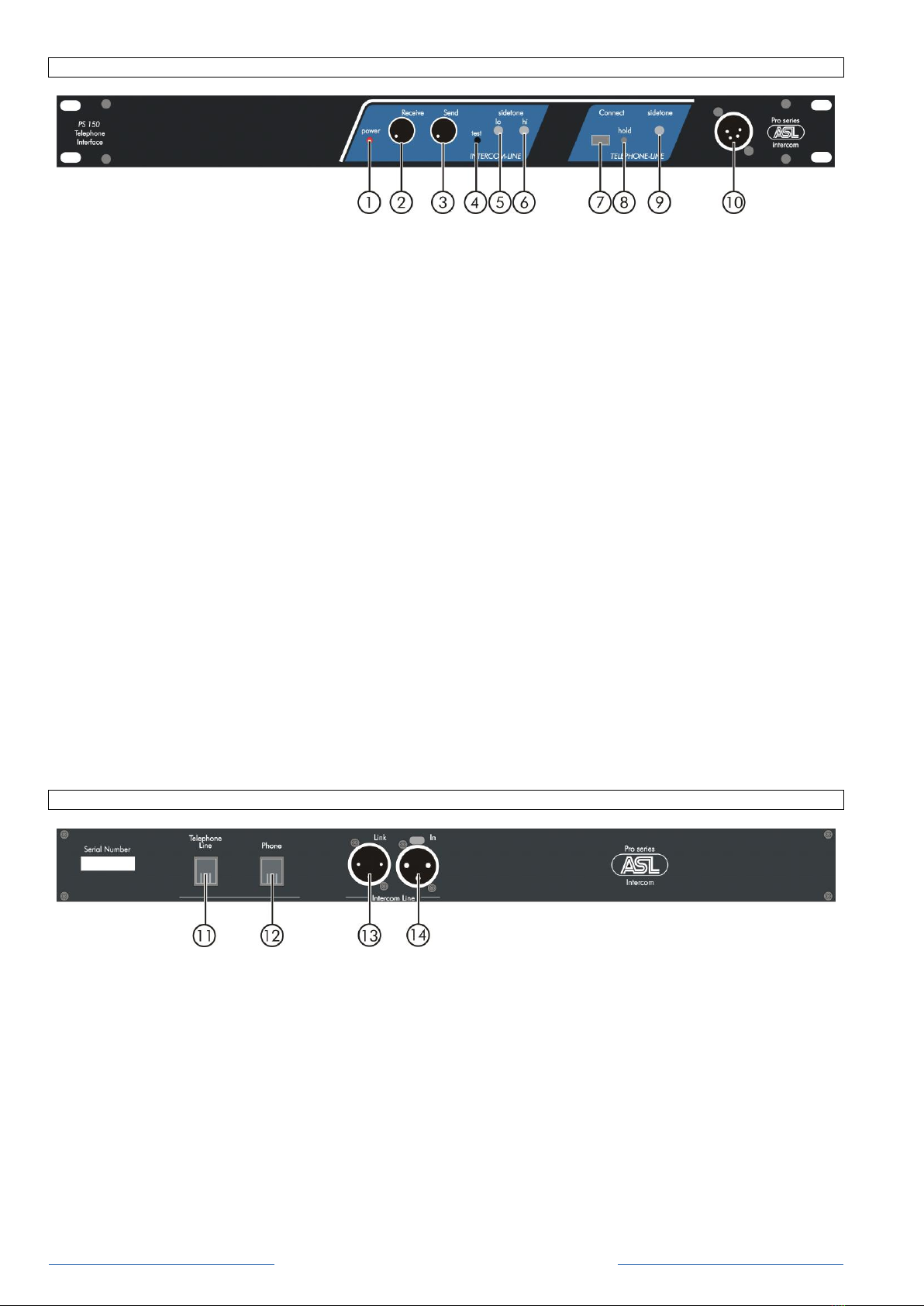
The intercom lines (the „party lines‟) are of the shielded two-conductor microphone cable type. The intercom line
connectors are of the XLR-3 type. Audio and Call signals are on pin 3, DC power is on pin 2 and pin 1 is
connected to the shield of the cable which functions as the common return for audio and power.
The audio signal is transferred in an unbalanced way (see „Party Line, Technical Concept‟).
To avoid earth loops (hum), the possible effect of electromagnetic fields and to minimize power loss, certain rules
have to be obeyed when installing the cabling of an intercom system :
Use high quality cable
Use high quality microphone cable (shielded two
conductor cable, minimum 2x 0.30 mm2).
In case multi-pair microphone cable is used, it
should consist of two conductors (minimum 2x 0.15
mm2) with separate shield and an overall shield.
Use flexible cable
Use flexible single and multi-pair microphone cable
instead of cable with solid cores, especially when
the cable is subjected to bending during operation or
installation.
Cable screens to XLR pin 1
The screen of each separate microphone cable
and/or the screen of each single pair in a multi-pair
cable should be connected to pin 1 of each XLR-3
connector. Do not connect these screens to the
metal housing of ASL units or XLR-3 wall boxes.
See section „Earthing Concept‟.
Connect metal cable trunks, wall boxes and
overall multi-pair cable screens to clean earth
Metal cable trunks, metal wall boxes and overall
multi-pair cable screens should be interconnected
and, at the 'central earth point' in the intercom
network, be connected to a clean earth or a safety
earth. See section „Earthing Concept‟.
Keep metal connection boxes and cable trunks
or pipes isolated from other metal parts
Metal trunks or pipes for intercom cables and metal
connection boxes should be mounted in such a way
that they are isolated from any other metal housing
or construction part.
Keep cables parallel as much as possible
When two (multi channel) units in a network are
connected by more than one cable, make sure that
these cables are parallel to each other over the
whole distance between those units. When using
multi-pair cable, parallelism is ensured in the best
possible way.
Avoid closed loops
Always avoid that intercom cables are making a
closed loop. So-called 'ring intercom' should not
physically be cabled as a ring..
Keep cables away from electromagnetic sources
Keep intercom cables away from high energy
cables, e.g. 115/230/400V mains power or dimmer
controlled feeds for spotlights. Intercom cables
should cross high energy cables at an angle of 90º
only. Intercom cables should never be in the same
trunks as energy cables.
Place power supply in a central position
In case of a system powered by a separate power
supply: In order to diminish power losses, place the
power supply as close as possible to where most
power consumption occurs, in other words most
user stations are placed.
ASL powered units to a 'clean' mains outlet
Master stations or power supplies should be
connected to a mains outlet with a clean earth.
Other audio equipment may be connected to this
mains outlet, but avoid using an outlet which also
powers dimmer controlled lighting systems.

PAGE 7
User Manual PS 150 / May 2011 © ASL Intercom BV
13.0 EARTHING CONCEPT
14.0 BLOCK DIAGRAM PS 150

PAGE 8
User Manual PS 150 / May 2011 © ASL Intercom BV
15.0 POSSIBLE SYSTEM CONFIGURATION
Table of contents
Other ASL INTERCOM Recording Equipment manuals