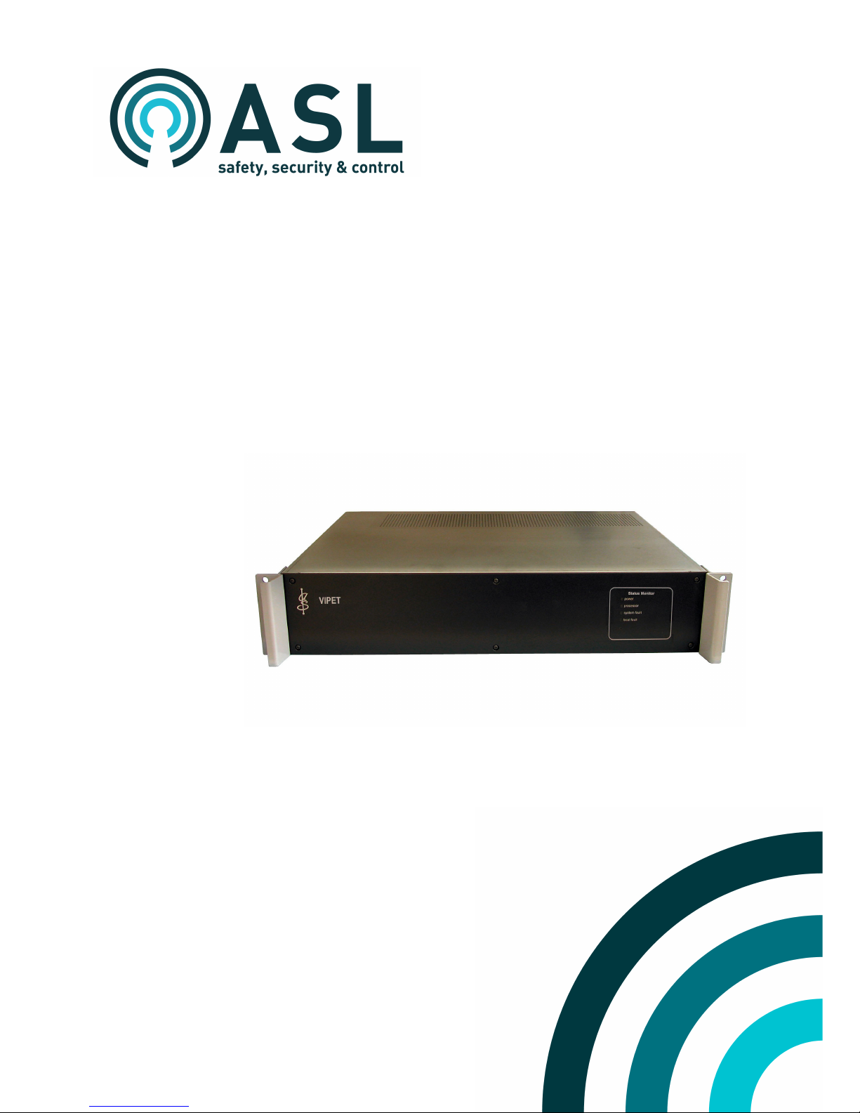
VIPET - Hardware Installation and Maintenance Guide
U-0582-0512.doc – Issue: 05 complete, approved
Page 3 of 24
1 General Information
Technical Specification Summary
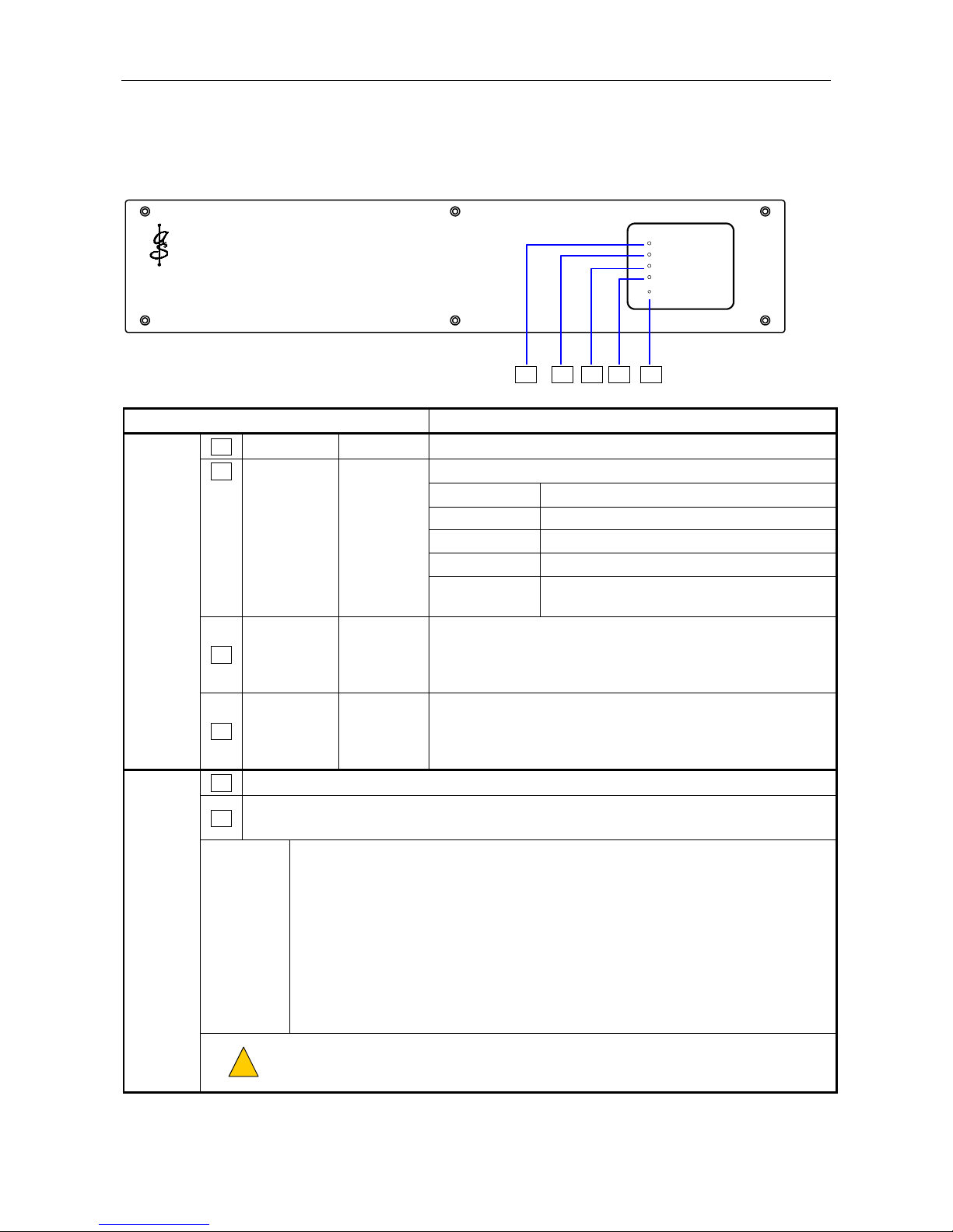
VIPET-FRAME
Processor.................................................................................................................................................x86, 1GHz, fanless
Power Consumption..........................................................................................................1.5A @24V DC / 200mA @230V AC
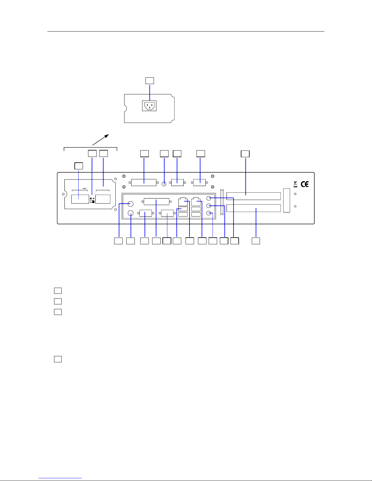
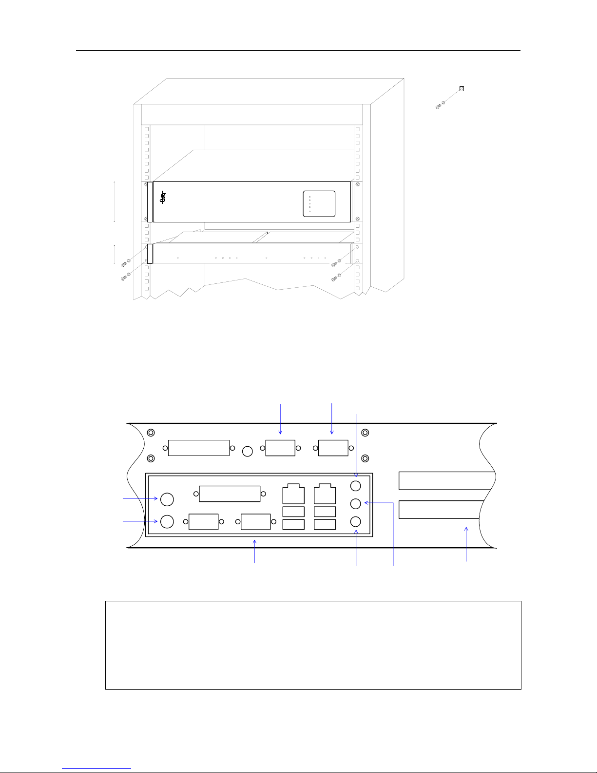
Number of RS232 Ports ..................................................................................................................................................... 21
Number of RS485 Ports ..................................................................................................................................................... 21
Number of RJ-45 Ports................................................................................................................... 2 / 100BASE-T Ethernet
Number of PCI Slots ........................................................................................................................................................... 2
Number of USB Ports...........................................................................................................................................4 / USB 2.0
Dimensions (H x W x D) ..........................................................88mm x 437mm x 325.32mm (excl. handles and connectors)
Weight...........................................................................................................................................................................6.8kg
Temperature
Storage.................................................................................................................................................... −20°C to +55°C
Operation................................................................................................................................................. −10°C to +55°C
Humidity Range......................................................................................................................... 0% to 95% Non-condensing
VIPET-PSU-MAINS (Mains Power Supply)
Power Supply ........................................................................................................................................................... 230V AC
Mains Filter............................................................. VIPET-MAINS-FILTER, ordered separately (up to 5 VIPETs per filter2)
Connector .......................................................................................................................................................IEC320 socket
Mounting .................................................................................................................................................... VIPET rear panel
VIPET-PSU-24V (DC Power Supply)
Supply Voltage Range ............................................................................................................21V–40V DC (nominal 24V DC)
Under Voltage Shut-down....................................................................................................................................... @21V DC
Connection ......................................................................................................... 2-way pluggable female Wago cage clamp
Mounting .................................................................................................................................................... VIPET rear panel
VIPET-SERIAL-4 (USB to RS485 port expander)
Number of RS485 Ports ...................................................................................................................................................... 4
RS485 Connectors............................................................................................................................................... 9-WD male
VIPET Connector ..................................................................................................................................................USB type B
Accessory................................................................................................................ Wall mounting power adapter supplied
Mounting ........................................................ External to VIPET / Purpose designed 1U 19” rack mounting shelf provided
1One of the RS232 ports can be set to RS485 by internal link. By default, it is set to RS232.
The total number of RS485 and RS232 ports is three, without extra expansion units.
2Maximum of 5 VIPETs to be powered through any one filter, whether they be connected directly to the filter, through number of UPS
units, or combination of the two.