manuals.online logo
Brands
  1. Home
  2. •
  3. Brands
  4. •
  5. ASP
  6. •
  7. Water Pump
  8. •
  9. ASP SSPC User manual

ASP SSPC User manual

Other manuals for SSPC

2

Other ASP Water Pump manuals

ASP SSPC Guide

ASP

ASP SSPC Guide

ASP TSP Manual

ASP

ASP TSP Manual

ASP FSPO Manual

ASP

ASP FSPO Manual

ASP SSPC Guide

ASP

ASP SSPC Guide

Popular Water Pump manuals by other brands

Watershed Innovations HYDRAPUMP SMART FLEX Instructional manual

Watershed Innovations

Watershed Innovations HYDRAPUMP SMART FLEX Instructional manual

Graco Modu-Flo AL-5M instructions

Graco

Graco Modu-Flo AL-5M instructions

Messner MultiSystem MPF 3000 operating instructions

Messner

Messner MultiSystem MPF 3000 operating instructions

Xylem Bell & Gossett WEHT0311M Installation, operation and maintenance instructions

Xylem

Xylem Bell & Gossett WEHT0311M Installation, operation and maintenance instructions

WilTec 50739 Operation manual

WilTec

WilTec 50739 Operation manual

Franklin Electric Little Giant 555702 HRK-360S instruction sheet

Franklin Electric

Franklin Electric Little Giant 555702 HRK-360S instruction sheet

Ingersoll-Rand PD02P Series Operator's manual

Ingersoll-Rand

Ingersoll-Rand PD02P Series Operator's manual

VS ZJ Series Operating	 instruction

VS

VS ZJ Series Operating instruction

Flotec FPZS50RP owner's manual

Flotec

Flotec FPZS50RP owner's manual

SKF Lincoln FlowMaster II User and maintenance instructions

SKF

SKF Lincoln FlowMaster II User and maintenance instructions

Xylem Lowara LSB Series Installation, operation and maintenance instructions

Xylem

Xylem Lowara LSB Series Installation, operation and maintenance instructions

Water Duro Pumps DCJ500 Operating & installation instructions

Water

Water Duro Pumps DCJ500 Operating & installation instructions

Action P490 Operating instructions & parts manual

Action

Action P490 Operating instructions & parts manual

Flo King Permacore Reusable Carbon Bag Disassembly. & Cleaning Instructions

Flo King

Flo King Permacore Reusable Carbon Bag Disassembly. & Cleaning Instructions

ARO ARO PD15P-X Operator's manual

ARO

ARO ARO PD15P-X Operator's manual

Pumptec 112V Series Operating instructions and parts manual

Pumptec

Pumptec 112V Series Operating instructions and parts manual

Virax 262070 user manual

Virax

Virax 262070 user manual

Neptun NPHW 5500 operating instructions

Neptun

Neptun NPHW 5500 operating instructions

manuals.online logo
manuals.online logoBrands
  • About & Mission
  • Contact us
  • Privacy Policy
  • Terms and Conditions

Copyright 2025 Manuals.Online. All Rights Reserved.

CONTROLLED DOCUMENT
WORK INSTRUCTION
Work Instruction No.
WI_AB_CXXXXXXXXX
Author
Matt Beckerdite
Rel. Date
11/26/13
Rev.
a
Description
Assembly of Model SSPC closed impeller pump
Safety Equipment
Flexible Gloves to protect against cuts
Safety Guidelines
Equipment and Tools
See Step 1 that describes the tools used
Introduction: This procedure describes the process for assembling a Model SSPC enclosed impeller pump. These pumps have a catalog number that
begin with a C1 and C2. The BOM will list the specific parts used such as o-rings, mechanical seals, cases, motor etc.
WORK INSTRUCTION
Work Instruction No.
WI_AB_CXXXXXXXXX
2
Exploded View Diagram of SSPC Pump Assembly
WORK INSTRUCTION
Work Instruction No.
WI_AB_CXXXXXXXXX
3
Step 1
Tools
(Air) ratchet with ¼” socket
Drain plug installation bit (1/4” square
socket by 3/8” Square socket for drain
plug)
Extended allen bits:
-3/16” allen for case screws (Qty 8)
-7/32” allen for adapter screws (Qty 4)
Tool Rack with all
the necessary bits
Electric Drill (for removing wire cover screws)
¼” hex drill bit (for removing wire covers)
Step 2 (3 phase motors only)
Drill and tap the motor
Single Phase motors shall skip this step!!!
If the motor is a 3-phase motor, it has the capability of rotating in either direction. In
order to keep the impeller from spinning off the shaft during a startup that rotates the
motor in the incorrect direction (counter clockwise), a locking screw and washer is used
with thread-locking compound.
See work instruction WI_M_DTMOT for details on this procedure. Nidec motors will use
a ¼-20” LH rotation screw and come tapped from the factory, while all others use a ¼”-
28 RH rotation locking screw. This hole is drilled and tapped at ASP.
Step 3
Gather Parts
Gather the parts located on the work order/BOM.
WORK INSTRUCTION
Work Instruction No.
WI_AB_CXXXXXXXXX
4
Step 4
Remove back plug from motor
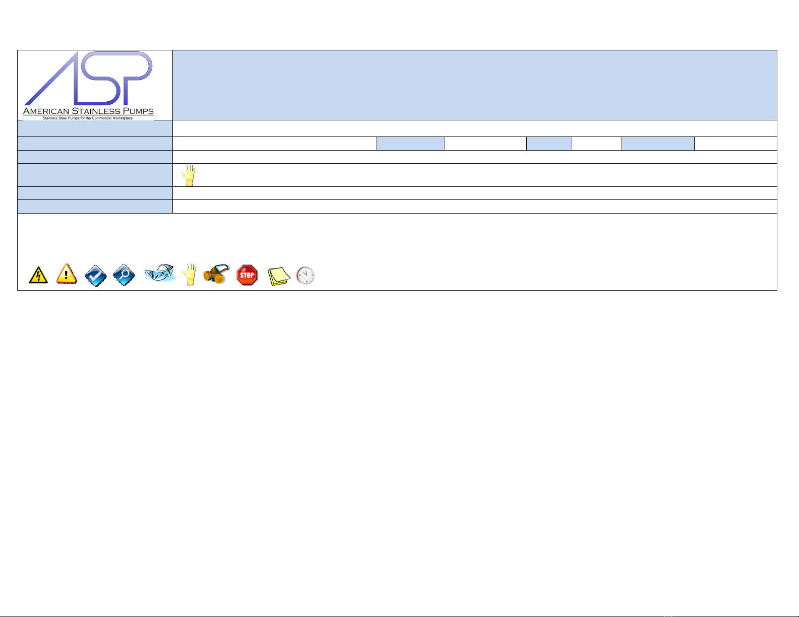
The motor manufacturer supplies a plug in the back of the motor. It can be seen in this
picture as a black plug at the center of the motor.
This plug must be removed in order to access the shaft during impeller installation.
The wire box cover shall also be removed in preparation for testing. (In the field, the
motor may be wired by accessing the wire port in the back/side of the motor and
installing an elbow.)
Step 5
Install Stationary Seal into Sealplate
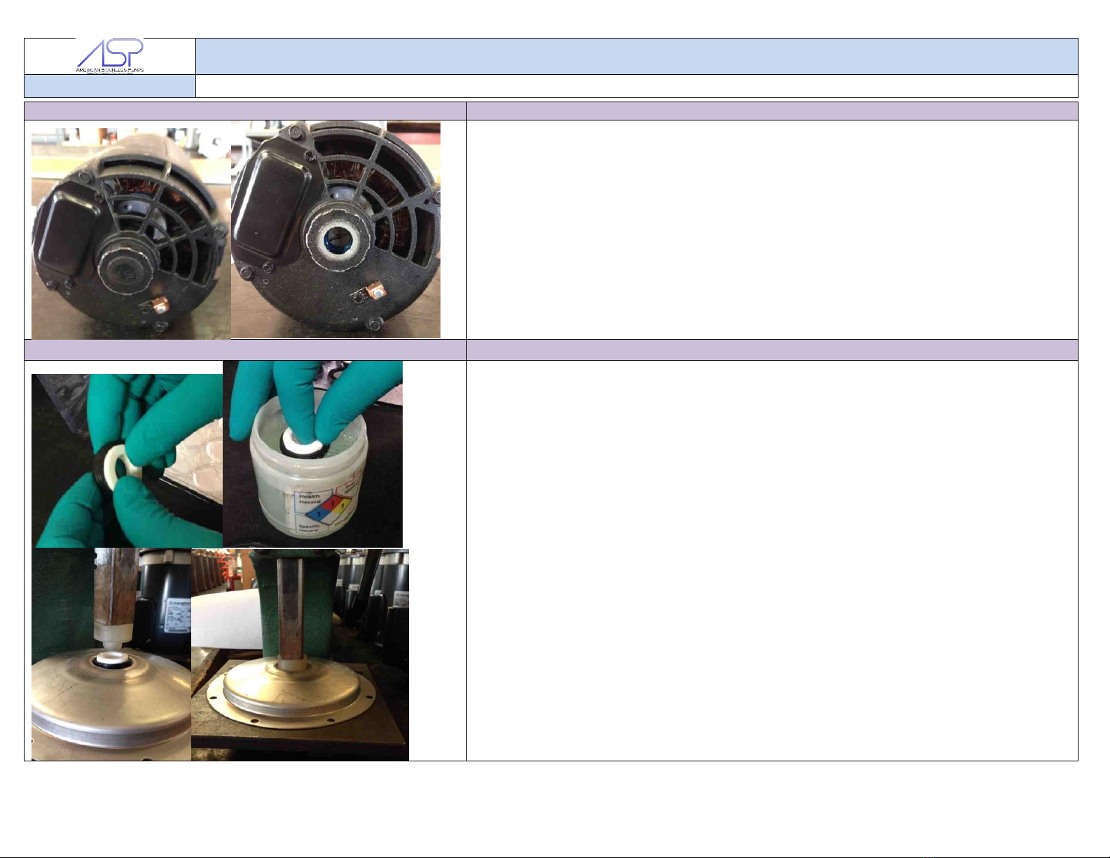
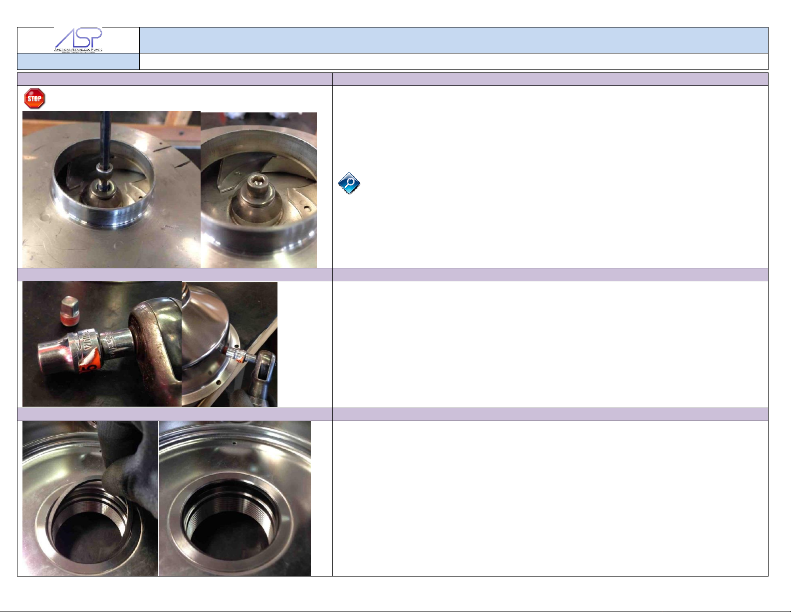
Using gloves to protect the seal faces from debris, dirt and fingerprints, massage the
seal into the seal seat (rubber). The seat needs to sit flat against the bottom of the seal
seat. Any tilt could lead to reduced seal life.
Dip the seal seat (rubber) into the pre-prepared lubricating solution (non-abrasive dish
soap/water combo). Be careful not to get solution on the face of the seal. Any solution
on the face of the seal may cause the stationary face to stick to the rotating face.
Place the stationary seal into the sealplate (as pictured).
Using the arbor press, place the sealplate into the proper location on the arbor press
plate. The press and plastic tool should come down directly into the center of the seal
without touching the sides.
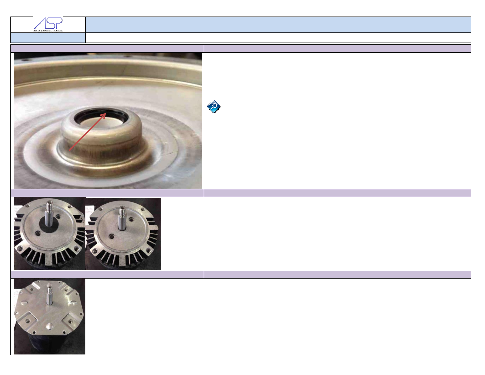
Pull down on the press handle and press the stationary half of the seal down until it is
stopped by the sealplates bore.
Rotate the sealplate 90 degrees and press, repeating 3 times until four sides of the seal
have been pressed down, ensuring the seal sits flat in the sealplate.
WORK INSTRUCTION
Work Instruction No.
WI_AB_CXXXXXXXXX
5
Step 6
Inspecting the Installed Seal for Proper Installation
View the seal from the backside to ensure the seal has been pressed all the way into
the sealplate bore. There should be no gap present between the seal and the bore.
Step 7
Setup Motor for Component Installation and Remove Slinger
Setup the motor on its rear end. The motor shaft should be sticking up into the air.
Remove the rubber slinger from the motor. If a slinger is not present, collect a slinger
from the “SLINGER” box/tray for later installation. The slinger spins and kicks off any
water drops during operation, preventing it from getting into the motor.
Step 8
Install Adapter Plate
Install the adapter plate onto the motor. The 4 bolt holes should line up with the motor
mounting holes.
WORK INSTRUCTION
Work Instruction No.
WI_AB_CXXXXXXXXX
6
Step 9
Re-install Slinger
Place the slinger back over the shaft and press it against the adapter plate
Step 10
Install Adapter Plate Screws
Install the 4 motor mounting bolts by hand. This prevents the threads from galling or
breaking with installation using an air ratchet.
Tighten the motor bolts completely, using the air ratchet. The bolts should be
approximately 12 ft-lbs and can be verified with a torque wrench.
Step 11
Install the Sealplate
Locate the sealplate carefully over the shaft.
The seal should not touch the shaft during assembly. This will prevent the seal
face from chipping or becoming damaged.
When the sealplate is tight against the motor adapter plate, the motor shaft should not
be touching the stationary seal. Press the flanges of the sealplate and motor adapter
plate together with your hands for an approximate location.
The gap surrounding the shaft should be very close to concentric. If the gap does not
seem concentric, the motor adapter plate shall be inspected for proper tab height and
dimensions. See QA.
WORK INSTRUCTION
Work Instruction No.
WI_AB_CXXXXXXXXX
7
Step 12
Installing the O-Ring and Rotating Half of the Mechanical Seal
Install the o-ring onto the sealplate as shown in the picture. The o-ring should not be
twisted or rolled.
Place one side of the o-ring over the sealplate. With two fingers, stretch the o-ring over
the other side while being careful not to roll the o-ring.
Ensure the o-ring is flat against the flange of the sealplate.
Step 13 (3 phase, 3HP and 5HP motors only!!!)
Applying Thread Locking Compound to the Impeller Threads
(3 phase, 3HP and 5HP motors only!!!)
Apply a drop of thread locking compound to the impeller threads prior to installation.
This process will help prevent the impeller from spinning off the shaft during a
reverse rotation.
When the impeller is screwed onto the motor shaft, the thread locking compound will
screw into the threads along the entire shaft.
WORK INSTRUCTION
Work Instruction No.
WI_AB_CXXXXXXXXX
8
Step 14
Installing the Impeller
Screw the impeller onto the motor shaft in a clockwise
direction. In order to completely tighten the impeller,
place a screwdriver into slot located in the back of the
motor and spin the impeller.
The impeller needs to completely butt up against the
shoulder of the shaft. Failure to do so may result in
damage to the impeller and the motor during startup.
Step 15 (For 3 Phase motor Only)
Installing the thread locking Compound
Skip this step if the motor is single phase!!!
Place a drop of thread locking compound onto the threads of the locking screw. The
compound should cover approximately 75% of the threads.
Too much compound will make the impeller very difficult to remove after some time in
the field.
WORK INSTRUCTION
Work Instruction No.
WI_AB_CXXXXXXXXX
9
Step 16 (For 3 Phase motor Only)
Installing the Locking Screw and Washer
Skip this step if the motor is single phase!!!
Place the screw listed on the work order BOM into the motor shaft.
-Left Hand screws will be rotated counter clockwise to tighten (Nidec Motors)
-Right Handed screws will be tightened clockwise to tighten
Rotate the screw by hand until it stops at the impeller hub. Tighten the screw to
approximately 8 ft-lbs.
The lock washer should not move or wiggle. Test that the washer is tight by trying to
wiggle it with your hand. If the washer moves, the motor shaft is not tapped far enough
and the pump needs to be disassembled (or a shorter locking screw may be used if in
the field).
Step 17
Install the Drain Plug into the Case
Using the 1/4” square socket by 3/8” Square socket for drain plug, tighten the drain
plug assembly into the case. Once the air ratchet stops, turn the drain plug another 60
degrees by hand to ensure it is sealed.
The drain plug should still have a minimum of 1 thread showing. If there is not 1 thread
showing, the port threads are too deep and the case may leak from these threads.
A new case is required. See QA for instructions.
(In the field, more Teflon tape or plumbers tape may be added to the drain plug.)
Step 18
Installing the Suction O-Ring
Place the suction o-ring into the groove of the suction nozzle.
The o-ring should float in the groove and should not be pinched or rolled.
WORK INSTRUCTION
Work Instruction No.
WI_AB_CXXXXXXXXX
10
Step 19
Installing the Case Assembly
Place the case onto the sealplate, over the o-ring.
Ensure the holes in the case flange, sealplate, and motor adapter are aligned by
placing an extended 3/16” allen bit through the holes. Wiggle the bit to line up all the
holes.
By hand, thread the case bolts through the 8 holes in the case flange and into the
motor adapter plate.
Leave the bottom 2 screws out if using a stainless steel baseplate. (Check the
BOM on the work order). This can be seen in the picture on the right.
If using a baseplate, inspect the baseplate to ensure the rubber cushion is installed on
the radius of the baseplate. If not, install the rubber trim.
Install the bolts on top of the baseplate, sandwiching the baseplate between the screw
and the case flange.
Tighten the screws in a crisscross pattern until tight (approximately 8 ft-lbs) using the
air ratchet and a 3/16” allen bit.